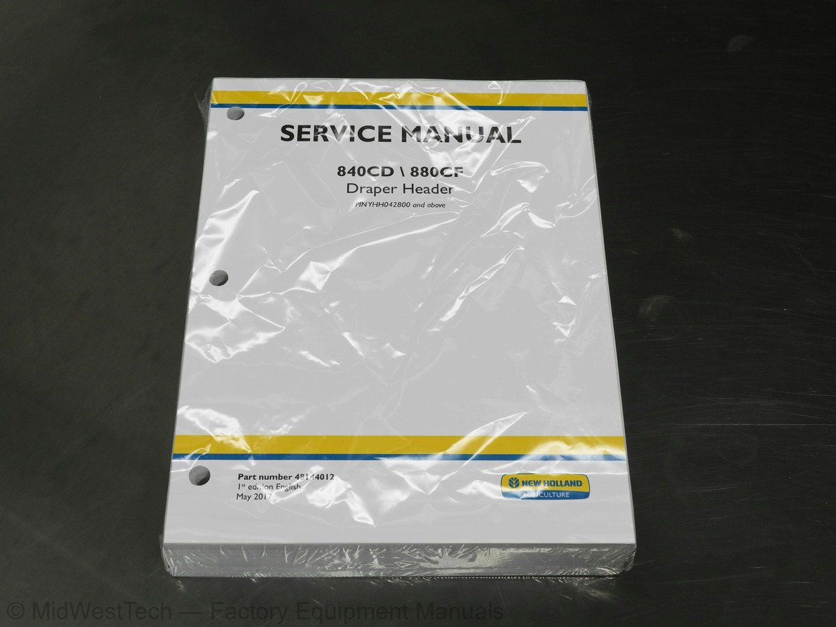
New Holland 840CD, 880CF Draper Header Service Manual
527 pages · Publication 48144012
Added to your cart. View cart
What's inside
From the manual's own table of contents: 184 topics. See sample pages (PDF, 532 KB)
- Hydraulic systems
- Reservoir, cooler, and filters
- Main control valve
- Reel vertical positioning system
- Reel fore-and-aft positioning system
- Head and header hydraulic drive
- Wheels
- Gauge wheels
- Electrical systems
- Electrical system
- Harnesses and connectors
- Header leveling control
- Reel speed and position control
- Feeding control system
- External lighting
- Attachments/Headers
- Attachment/Header support and drives
- Attachment/Header reel
- Attachment/Header reel control system
- Attachment/Header cutting mechanism
- Attachment/Header feed auger
- Attachment/Header frame
- Header drive
- Belt feeding
Show all 184 topics
- Foreword - Important notice regarding equipment servicing (*)
- Safety rules - Ecology and the environment (*)
- Safety rules (*)
- Safety rules - Personal safety (*)
- Power Take-Off (PTO) shaft - Safety rules - Power Take-Off (PTO) (*)
- Transport locking assembly Cylinder stop - Safety rules - Lift cylinder safety locks (*)
- Safety signs
- Torque - Minimum tightening torques for normal assembly (*)
- Torque - Standard torque data for hydraulics (*)
- Basic instructions - Shop and assembly (*)
- Basic instructions - Chain wear tables - Roller chains (*)
- General specification - General welding (*)
- General specification Machine specifications - Flex headers (*)
- General specification Machine specifications - Rigid headers (*)
- Capacities (*)
- Product identification (*)
- Machine orientation - Machine orientation
- General specification - Double gear pump (*)
- General specification - Side draper motor (*)
- General specification - Pea auger drive motor (*)
- General specification - Reel drive motor (*)
- General specification - Feed draper motor (*)
- General specification - Knife drive motor (*)
- General specification - Hydraulic reservoir and expansion tank (*)
- General specification - Hydraulic system accumulator (*)
- General specification - Transport valve (*)
- Component identification - Hydraulic components (*)
- Overview - Hydraulic components (*)
- Hydraulic schematic frame 01 (*)
- Hydraulic schematic frame 02 (*)
- Hydraulic schematic frame 03 - Central knife drive - Forward (*)
- Hydraulic schematic frame 03 - Central knife drive - Reverse (*)
- Hydraulic schematic frame 04 - Draper and pea auger drives - Forward (*)
- Hydraulic schematic frame 04 - Draper drive - Reverse (*)
- Hydraulic schematic frame 05 - Draper drive - Accumulator discharge - Forward (*)
- Hydraulic schematic frame 06 - Reel fore/aft (*)
- Hydraulic schematic frame 07 - Cutterbar floatation option (*)
- Hydraulic schematic frame 08 - Frame tilt (*)
- Hydraulic schematic frame 09 - Slow speed transportation option (*)
- Component localization
- Change fluid - Main
- Check - Main
- Change fluid - Expansion
- Check - Expansion
- Sectional view (*)
- Service instruction (*)
- Remove - Reel lift (*)
- Install - Reel lift (*)
- Bleed (*)
- Inspect
- Remove
- Disassemble (*)
- Assemble (*)
- Install
- Remove - Lower link
- Install - Lower link
- Remove - Spring assembly
- Install - Spring assembly
- Overview (*)
- Overview Potentiometers (*)
- Overview Pressure sensors (*)
- Overview Solenoids (*)
- Component identification Lamp & LED: E-001 - E-008 (*)
- Component identification Resistor: R-001 - R-025 (*)
- Component identification Solenoid: Y-001 - Y-004 (*)
- Electrical test Open Circuit (*)
- Electrical test Short to Ground (*)
- Electrical test Short to Voltage (*)
- Testing General Wire Testing (*)
- Electrical schematic sheet 01 - Draper Header Type / Reel Position/Height (*)
- Electrical schematic sheet 02 - Draper Header Lights/Hydraulic (*)
- Electrical schematic sheet 03 - Draper Header Transport Lights (*)
- Component diagram 00 Connectors X-030 to X-039 (*)
- Component diagram 00 Connectors X-220 to X-229 (*)
- Component diagram 00 Connectors X-250 to X-259 (*)
- Component diagram 00 Connectors X-300 to X-309
- Component diagram 00 Connectors X-430 to X-439 (*)
- Component diagram 00 Connectors X-520 to X-529 (*)
- Component diagram 00 Connectors X-700 to X-709 (*)
- Replace (*)
- Remove (*)
- Install (*)
- Left-hand stubble height sensor - Testing Left Height/Tilt (*)
- Left-hand stubble height sensor - Testing Left Center Height (*)
- Right-hand stubble height sensor - Testing Right Center Height (*)
- Right-hand stubble height sensor - Testing Right Height/Tilt (*)
- Exploded view (*)
- Main gearbox and drive - Overview (*)
- Remove Slip clutch
- Assemble
- Disconnect - Quick release coupler
- Disassemble - Quick release coupler
- Problem solving (*)
- Exploded view
- Remove - Single reel
- Remove - Split reel
- Install - Single reel
- Install - Split reel
- Adjust - Tine pitch
- Special tools (*)
- General specification
- Identification (*)
- Drain fluid
- Remove - Flex headers (*)
- Remove - Rigid headers (*)
- Install - Flex Headers (*)
- Install - Rigid headers (*)
- Remove - Knife
- Remove - Torsion spring (*)
- Replace - Knife section
- Replace - Knife guard
- Adjust (*)
- Install - Knife
- Install - Torsion spring (*)
- Filling
- Disassemble housing (*)
- Remove output shafts (*)
- Install output shafts (*)
- Inspect - Output shaft (*)
- Cleaning - Seal replacement (*)
- Remove pinion shaft (*)
- General specification - Flighting clearance (*)
- Adjust - Auger fingers (*)
- Upper cross auger - Remove - Left-hand auger (*)
- Upper cross auger - Remove - Center auger (*)
- Upper cross auger - Remove - Right-hand auger (*)
- Upper cross auger - Install - Left-hand auger (*)
- Upper cross auger - Install - Center auger (*)
- Upper cross auger - Install - Right-hand auger (*)
- Upper cross auger - Adjust (*)
- Exploded view - Side draper (*)
- Exploded view - Infeed Draper (left-hand) (*)
- Exploded view - Infeed Draper (right-hand) (*)
- Remove - Drive coupler (*)
- Remove - Roller shaft - Side draper (*)
- Remove - Roller shaft - Infeed draper (left-hand) (*)
- Remove - Roller shaft - Infeed draper (right-hand) (*)
- Replace Side draper roller bearing (*)
- Replace Infeed draper roller bearing (*)
- Install Roller shaft - Side draper (*)
- Install Roller shaft - Infeed draper (left-hand) (*)
- Install Roller shaft - Infeed draper (right-hand) (*)
- Install - Drive coupler (*)
- Remove Side draper belt (*)
- Remove Infeed draper belt (*)
- Remove - Side draper frame (*)
- Remove Infeed draper frame - Flex headers (*)
- Remove Infeed draper frame - Rigid headers (*)
- Install - Infeed draper frame - Flex headers (*)
- Install - Infeed draper frame - Rigid headers (*)
- Install - Side draper frame (*)
- Install - Infeed draper belt (*)
- Install - Side draper belt (*)
- Adjust side draper tension (*)
- Adjust infeed draper tension (*)
- Adjust side draper tracking (*)
- Remove the right-hand side shield (*)
- Install the right-hand side shield (*)
- Remove the left-hand side shield (*)
- Install the left-hand side shield (*)
Inside this manual
Real pages from this service manual (527 pages). Open the sample pages (PDF, 531 KB)

- Specifications, page 40: INTRODUCTION
- Diagram, page 184: Electrical systems - Electrical system
- Repair procedure, page 472: Attachments/Headers - Belt feeding
- Color page, page 23: INTRODUCTION
This is a service manual
Here's how it compares to the other manual types.
Service manual
Factory repair procedures and technical information such as specifications, troubleshooting, and wiring and hydraulic diagrams, for the models and systems the manual covers. See What's inside for its topics.
Operator's manual
Safe operation, controls, maintenance schedules, lubrication points, inspections, and basic checks. Repair procedures are in the service manual.
Parts manual
Illustrated diagrams with factory part numbers for identifying components and ordering parts. Repair procedures are in the service manual.
Engine service manuals are sometimes sold separately, since certain machine models were offered with more than one engine option.
What it's used for
Factory manual for in-house farm and construction shop use. Straightforward, complete, and easy to follow. It contains the OEM information dealership service departments and parts counters use to diagnose problems, identify components, and perform maintenance or repairs correctly.
Service shops and owner/operators who repair their own equipment
Identifying correct parts and seeing how assemblies come apart and go back together
Keeping equipment running with less downtime
Factory manual, 527 pages
Quantity one is the manual described above.
Fast free USA shipping
Ships in 1 business day.
60-day returns
Free if the mistake is ours. A manual ordered in error must come back unopened in its shrink-wrap; you pay return shipping and a 20% restocking fee applies. Return policy
Binder not included
Manuals over about 300 pages may need a standard 3-ring binder, which you can buy locally to keep the pages organized for shop use.
Other editions and similar models
Questions about model, serial number, engine coverage or contents? Contact us before purchasing and we'll help confirm it's the right manual. Please verify the manual type, machine model, serial number range and engine coverage before purchasing: manuals ordered in error carry a 20% restocking fee (return policy).