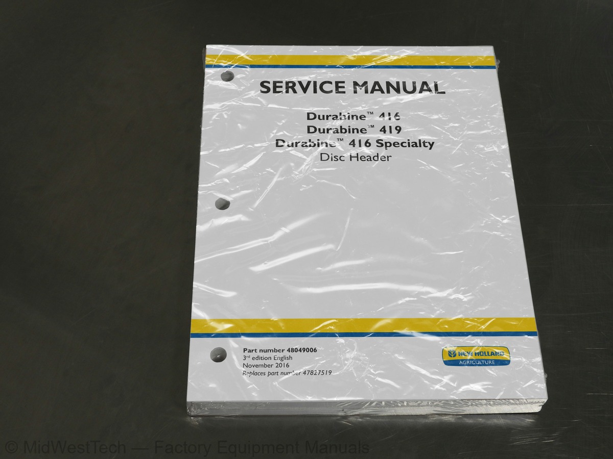
New Holland Durabine 416, 419 Specialty Disc Header Service Manual
441 pages · Publication 48049006
Added to your cart. View cart
- Models
- Durabine 416, 419 Specialty
- Manual type
- Service Manual
- Pages
- 441
- Publication
- 48049006
- Condition
- Brand new
What's inside
From the manual's own table of contents: 167 topics. See sample pages (PDF, 614 KB)
- Hydraulic systems
- Head and header hydraulic drive
- Frames and ballasting
- Drawbar and hitch assembly
- Wheels
- Gauge wheels
- Electrical systems
- Electrical system
- Harnesses and connectors
- External lighting
- Chopping and cutting control systems
- Attachments/Headers
- Attachment/Header support and drives
- Attachment/Header cutting mechanism
- Attachment/Header feed auger
- Attachment/Header frame
- Header drive
- Product feeding
- Header drive system
- Roll conditioning
- Flail conditioning
- Platform, cab, bodywork, and decals
- Decals and plates
- Foreword - Important notice regarding equipment servicing
Show all 167 topics
- Safety rules
- Safety rules - Personal safety
- Safety rules - Ecology and the environment
- Torque - Nominal tightening torques for normal assembly
- Torque - Standard torque data for hydraulic connections
- Basic instructions - Shop and assembly
- Specifications – General - Durabine™416 and Durabine™416 Specialty
- Specifications – General - Durabine™419
- Capacities
- Product identification
- Product identification - Machine orientation
- Technical Data
- Overview
- Hydraulic schema - PIN YGG627000 and before
- Hydraulic schema - PIN YGG627001 and after
- Identification
- Remove
- Install
- Remove - Motor lip seal (field replacement)
- Install - Motor lip seal (field replacement)
- Remove - Left-hand motor
- Disassemble - Left-hand motor
- Inspect - Left-hand motor
- Assemble - Left-hand motor
- Install - Left-hand motor
- Remove - Right-hand motor, PIN YGG627001 and after
- Disassemble - Right-hand motor, PIN YGG627001 and after
- Assemble - Right-hand motor, PIN YGG627001 and after
- Install - Right-hand motor, PIN YGG627001 and after
- Remove - Right-hand motor, PIN YGG627000 and before
- Service instruction - Right-hand motor, PIN YGG627000 and before
- Install - Right-hand motor, PIN YGG627000 and before
- Disassemble
- Assemble
- Remove - Gauge roller assembly
- Install - Gauge roller assembly
- Adjust - roller-to-scraper clearance
- Technical Data - Variable reluctance sensor
- Electrical schematic sheet 01 - Hazard lighting and speed sensing
- Component diagram 01 - Connectors X-010 to X-019
- Component diagram 19 - Connectors X-190 to X-199
- Component diagram 36 - Connectors X-360 to X-369
- Sensor description
- Lamp description
- Dynamic description
- Testing - Left-hand header hazard light circuit continuity check
- Testing - Right-hand header hazard light circuit continuity check
- Crop setting
- Dynamic description - Header knife speed sensor
- Adjust - Clearance
- Testing - Header knife speed sensor
- Dynamic description - Bevel gearbox
- Remove - Outer auger jackshaft bearing
- Install - Outer auger jackshaft bearing
- Remove - Auger jackshaft sprocket
- Install - Auger jackshaft sprocket
- gearbox
- Disc cutterbar - Exploded view - Disc module pinion shaft assembly
- Static description
- Remove - Cutterbar drive shaft
- Disassemble - Cutterbar drive shaft
- Assemble - Cutterbar drive shaft
- Install - Cutterbar drive shaft
- Cutterbar modules – Change fluid
- Cutterbar modules oil level – Check
- Service instruction - Detecting a sheared shock hub
- Remove - Shock hub
- Install - Shock hub
- Remove - Shock hub top cap
- Visual inspection - Shock hub top cap
- Install - Shock hub top cap
- Remove - Drive hub top cap
- Visual inspection - Drive hub top cap
- Install - Drive hub top cap
- Remove - Cutterbar module
- Disassemble - Cutterbar module
- Visual inspection - Disc module components
- Assemble - Cutterbar module orientation
- Install - Cutterbar module
- Visual inspection
- Visual inspection - Knives and hardware
- Remove - Bolt-on knives
- Install - Bolt-on knives
- Overview - Auger paddles
- Remove - Auger assembly (*)
- Install - Auger assembly (*)
- Adjust - Auger-to-stripper clearance
- Remove - Auger flight extension
- Install - Auger flight extension
- Remove - Auger paddles
- Install - Auger paddles
- Tension adjust
- Remove - Push bar divider
- Install - Push bar divider
- Remove - Push bar assembly
- Install - Push bar assembly
- Timing adjust - Conditioner Power Take-Off (PTO) drive shafts
- Remove - Motor coupler
- Disassemble - Motor coupler
- Assemble - Motor coupler
- Install - Motor coupler
- General information - Header speed chart
- Remove - Driven sheave
- Install - Driven sheave
- Remove - Drive sheave
- Install - Drive sheave
- Remove - Belt tensioner drive
- Install - Belt tensioner drive
- Change fluid
- Check fluid level
- Inspect
- Overview - Roll gap
- Overview - Roll pressure
- Remove (*)
- Install (*)
- Remove - Drive shaft
- Install - Drive shaft
- Roll conditioning - Adjust - Roll gap
- Disassemble - Drive shaft
- Assemble - Drive shaft
- Remove - Right-hand side (*)
- Remove - Left-hand side (*)
- Install - Right-hand side (*)
- Install - Left-hand side (*)
- Roll conditioning - Adjust - Roll pressure
- Roll conditioning - Timing adjust - Conditioner rolls
- Remove - Conditioner module (*)
- Install - Conditioner module (*)
- Remove - Flail conditioner module
- Install - Flail conditioner module
- Remove - Flails and flail shaft
- Install - Flails and flail shaft
- Remove - Hood liner
- Install - Hood liner
- Component localization
- Remove - Rear deck
- Install - Rear deck
- Remove - Door shield
- Install - Door shield
- Drive shields - Remove - Cutterbar drive tower - Left-hand
- Drive shields - Install - Cutterbar drive tower - Left-hand
- Drive shields - Remove - Cutterbar drive tower - Right-hand
- Drive shields - Install - Cutterbar drive tower - Right-hand
Inside this manual
Real pages from this service manual (441 pages). Open the sample pages (PDF, 614 KB)
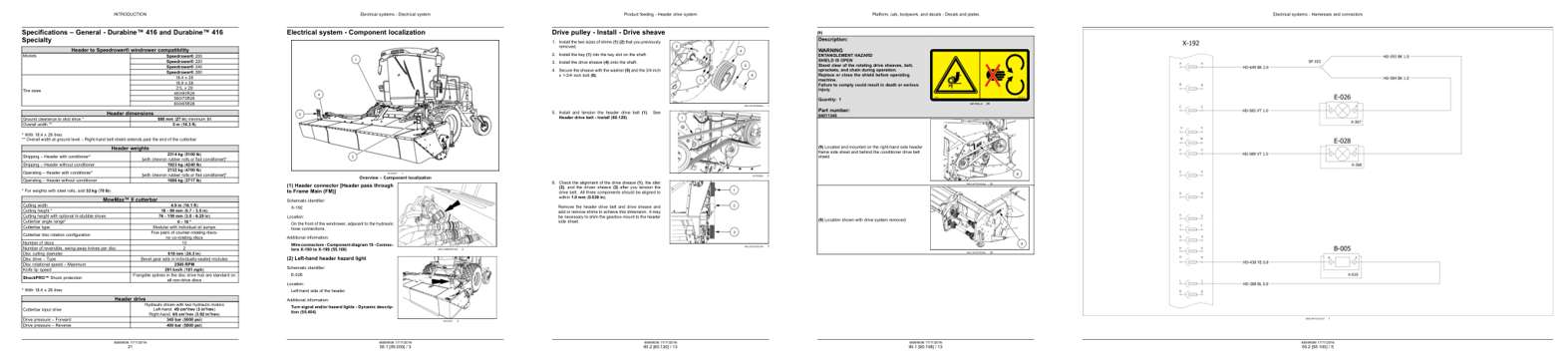
- Specifications, page 26: INTRODUCTION
- Diagram, page 116: Electrical systems - Electrical system
- Repair procedure, page 302: Product feeding - Header drive system
- Color page, page 416: Platform, cab, bodywork, and decals - Decals and plates
- Foldout diagram, page 124: Electrical systems - Harnesses and connectors
This is a service manual
Here's how it compares to the other manual types.
Service manual
Factory repair procedures and technical information such as specifications, troubleshooting, and wiring and hydraulic diagrams, for the models and systems the manual covers. See What's inside for its topics.
Operator's manual
Safe operation, controls, maintenance schedules, lubrication points, inspections, and basic checks. Repair procedures are in the service manual.
Parts manual
Illustrated diagrams with factory part numbers for identifying components and ordering parts. Repair procedures are in the service manual.
Engine service manuals are sometimes sold separately, since certain machine models were offered with more than one engine option.
What it's used for
Factory manual for in-house farm and construction shop use. Straightforward, complete, and easy to follow. It contains the OEM information dealership service departments and parts counters use to diagnose problems, identify components, and perform maintenance or repairs correctly.
Service shops and owner/operators who repair their own equipment
Identifying correct parts and seeing how assemblies come apart and go back together
Keeping equipment running with less downtime
Factory manual, 441 pages
Quantity one is the manual described above.
Fast free USA shipping
Ships in 1 business day.
60-day returns
Free if the mistake is ours. A manual ordered in error must come back unopened in its shrink-wrap; you pay return shipping and a 20% restocking fee applies. Return policy
Binder not included
Manuals over about 300 pages may need a standard 3-ring binder, which you can buy locally to keep the pages organized for shop use.
Questions about model, serial number, engine coverage or contents? Contact us before purchasing and we'll help confirm it's the right manual. Please verify the manual type, machine model, serial number range and engine coverage before purchasing: manuals ordered in error carry a 20% restocking fee (return policy).