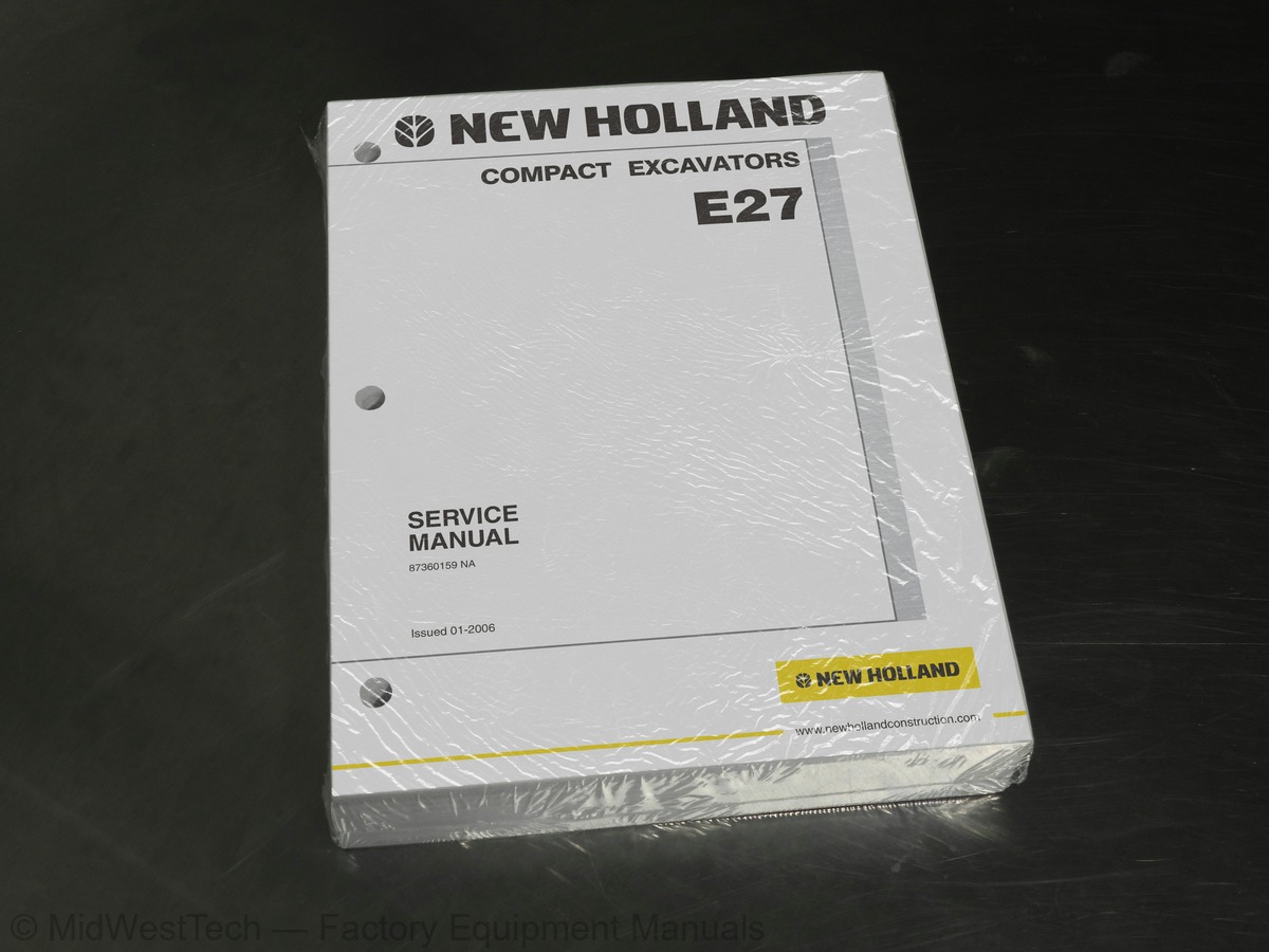
New Holland E27 Compact Excavator Service Manual
540 pages · Publication 87360159
Added to your cart. View cart
- Models
- E27
- Manual type
- Service Manual
- Pages
- 540
- Publication
- 87360159
- Condition
- Brand new
What's inside
From the manual's own table of contents: 9 sections, 429 entries. See sample pages (PDF, 937 KB)
STANDARD SPECIFICATIONS AND MAINTENANCE28 topics
- General Safety Information
- Safety Precautions
- General Precautions for Repairs
- International Unit Conversion System
- Components Name
- Machine Dimensions
- Specifications and Performance
- Machine and Components Weights (Dry)
- Transportation
- Type of Track Shoes
- Type of Bucket
- Engine Specifications
- Boom
- Bucket
- Dozer
- Swing
- Torque Specifications for Capscrews and Nuts
- Screw and Tool Sizes
- Torque Specifications for Joints and Hoses
- Torque Specifications for Sleeve Type Tube Fittings
- Plugs
- Special Spanners for Tubes
- Special Tools
- Application of Screw Locking and Sealing Compounds
- Counterweight Lifting Jig
- Upper Frame Lifting Jig
- Working Standards for Time Tables
- Time Tables
SECTION 1 - STANDARD SPECIFICATIONS AND MAINTENANCE89 topics
- Preparation Before Disassembling
- Safety In Disassembling and Assembling
- Disassembling and Assembling Hydraulic Equipment
- Electrical Equipment
- Hydraulic Parts
- Welding Repair
- Environmental Protection
- Introduction
- Speed and Grade ability
- Engine
- Hydraulic Components
- Side Digging and Dozer
- Weight
- Loading Machine on a Trailer
- Transportation Dimension and Weight of Attachment
- Boom with Arm Cylinder
- Arm and Bucket (Standard Bucket)
- Bucket (Standard Bucket)
- Dozer (Without Cylinder Weight)
- Specifications
- Engine Performance Curve
- Boom Dimensional Drawings
- Boom Maintenance Standards
- Clearance of Pin and Bushing on Boom Section
- Clearance in Thrust Direction on Boom and Cylinder Installation Section
- Arm Dimensional Drawings
- Arm Maintenance Standards
- Clearance of Pin and Bushing
- Clearance in Thrust Direction on Arm and Cylinder Installation Section
- Bucket Dimensional Drawings
- Detail Dimensional Drawings of Lug Section
- Detail Dimensional Drawings of Boss Section
- Dozer Dimensional Drawings
- Dozer Maintenance Standards
- Clearance of Pin and Bushing
- Clearance in Thrust Direction on the Dozer and Cylinder Installation Section
- Swing Bracket Dimensional Drawings
- Swing Portion Maintenance Standards
- Metric Coarse Thread Standard Tightening Torque Values
- Metric Fine Thread Standard Tightening Torque Values
- Capscrew
- Capscrew (Socket bolt)
- Joints for Piping (O-ring Sealing Type)
- Hydraulic Hose (30 Degree Flare TypE)
- Sleeve Type Tube Fittings
- Part Number
- Plug for Hydraulic Pipe Joint
- Cap Nut (Joint Plug)
- Plug (Tube Plug)
- Plug for Hydraulic Equipment
- PF Screw
- PT Screw
- Plug for Flare Hose
- Working Conditions
- Applicable Range of Standard Maintenance Time
- Excluded Time
- Applicable Machine for Estimation of Standard Maintenance Time
- Standard Maintenance Time Table
- Classification of Work Code
- Attachment - Group 01
- Canopy and Guard - Group 02
- Upper Structure - Group 03
- Under Carriage - Group 04
- Application
- Terminology
- Precautions for Judgment
- Other Precautions
- Engine Speed Measurement
- Standard For Hydraulic Oil Pressure Measurement
- Pressure Measurement and Adjustment
- Main Circuit Pressure
- Pilot Circuit Pressure
- Test Procedure
- Travel
- Travel Deviation
- Movement Drift due to gravity
- Drain Rate on Travel Motor
- Test Procedure
- Slew Time
- Overrun when Slewing Stops
- Slew Drift due to Gravity
- Drain Rate of Slew Motor
- Test Procedure
- Cylinder Speed
- Gravity Drift of Cylinders
- Test Procedure
- Slew Bearing-Bucket Tip Play
- Slew Bearing Play
- Track Tension
HYDRAULIC, ELECTRICAL, AND COMPONENT SYSTEMS8 topics
- Summary
- Hydraulic Circuits and Component Models
- Hydraulic Circuit Operation
- Schematic Piping for Hydraulic System
- How To Read Circuit Diagram and Harness Connection
- Electrical Equipment and Harness
- Hydraulic Components
- Electrical Equipment
SECTION 2 - HYDRAULIC, ELECTRICAL, AND COMPONENT SYSTEMS109 topics
- Function and Features Of Hydraulic Circuit
- Standard Specifications
- COLOR CODING STANDARD FOR HYDRAULIC
- NEUTRAL CIRCUIT
- TRAVEL OPERATING CIRCUIT
- 22.3.3.1 2nd Speed Operating Circuit (Independent-forward travel)
- SLEW OPERATING CIRCUIT
- Slew (left) Operating Circuit
- BUCKET OPERATING CIRCUIT
- Bucket Digging Operation Circuit
- Bucket Dumping Operating Circuit
- BOOM OPERATING CIRCUIT
- Boom Raise Operating Circuit
- Boom Lower Operating Circuit
- ARM OPERATING CIRCUIT
- Arm In Operating Circuit
- Operating Circuit for Arm Out
- SWING OPERATING CIRCUIT
- Swing (left) Operating Circuit
- DOZER OPERATING CIRCUIT
- Dozer Down Operating Circuit
- NIBBLER & BREAKER OPERATING CIRCUIT
- Nibbler Close Operating Circuit
- Nibbler Open Operating Circuit
- Breaker Blow Operating Circuit
- TRAVEL / DOZER COMBINED OPERATING CIRCUIT
- Travel (1st speed forwarding) /Dozer Down Operating Circuit
- TRAVEL / BOOM COMBINED OPERATING CIRCUIT
- Travel (1st speed forward) / Boom Up Operating Circuit
- See Schematics in Rear Pocket
- ELECTRIC CIRCUIT DIAGRAM
- HARNESS CONNECTION
- ELECTRICAL EQUIPMENT LIST
- HARNESS & CABLE LIST
- ARRANGEMENT DRAWING FOR COMPONENTS & HARNESS
- Upper Frame Portion
- Engine Portion
- Relay Unit Portion
- Fuel Tank Portion
- Work Light Portion
- Cab Portion (OPT)
- Travel Alarm Portion (OPT)
- Heater Portion (OPT)
- DETAIL OF HARNESS & CABLE
- Inst • Main Harness (No. H-1)
- Engine Harness (No. H-3)
- Starter Cable (+) (No. H-4)
- Battery Ground Cable (–) (No. H-5)
- Engine Ground Cable (No. H-6)
- Boom Harness (No. H-7)
- Key Switch Harness (No. H-8)
- Canopy Working Light Harness (No. H-9)
- Boom Work Light Extension Harness (No. H-10)
- Connection Harness with Cab (No. H-11) (OPT)
- Travel Alarm Harness (No. H-13)
- Alarm Extension Harness (No. H-14)
- Heater Harness (No. H-15) (OPT)
- Air Filter Restriction Switch Harness (No. H-16)
- Extension Harness For Relay (No. H-17)
- Extension Harness For Instrument Main Harness (No. H-18)
- Horn Switch Extension Harness (No. H-19)
- HYDRAULIC PUMP
- Summary
- Specifications
- Construction Function
- Inner Construction
- Swash plate (Hanger)
- Rotary group
- Control spring
- Cover
- Gear pump
- PILOT VALVE (ATT)
- Summary
- Operation
- PILOT VALVE (TRAVEL)
- Summary
- General View
- Specifications
- Performance Characteristics
- Construction
- Operation
- Reducing valve
- CONTROL VALVE
- General View And Hydraulic Ports No
- Specifications
- Hydraulic Circuit
- Explanation of Operation
- SLEWING MOTOR
- Function and Operation
- Slewing Motor
- TRAVEL MOTOR
- Summary
- Hydraulic circuit
- Construction
- Function
- SWIVEL JOINT
- Summary
- General View
- Specifications
- Construction
- Function
- CYLINDER
- Summary
- Specifications
- Construction and Function
- Boom cylinder
- Function (Example for boom cylinder)
- Electrical Equipment List
- Specifications Electrical Equipment
DISASSEMBLY AND ASSEMBLY7 topics
- General Disassembly and Assembly
- REMOVING AND INSTALLING
- DISASSEMBLING AND ASSEMBLING
- REMOVING AND INSTALLING
- DISASSEMBLING AND ASSEMBLING
- REMOVAL AND INSTALLATION
- DISASSEMBLING AND ASSEMBLING
SECTION 3 - DISASSEMBLY AND ASSEMBLY128 topics
- Attachment Assembly and Name
- Bucket
- Removal of Bucket
- Installation of Bucket
- Removal of Arm
- Installation of Arm
- Boom
- Removal of Boom
- Installation Of Boom
- Swing
- Preparation for Removal
- Removal Of Swing Bracket and Cylinder
- Installation Of Swing Bracket and Cylinder
- Dozer
- Removal
- Installation
- Cylinder
- Necessary Tools
- General Precautions
- Cylinder Construction (Example of Boom Cylinder)
- Disassembly
- Assembly
- Maintenance Standards
- Inspection After Disassembly
- Jig List
- Possible Causes For Trouble and Remedy
- CANOPY / CAB
- Canopy Removal
- Cab Removal (Option)
- Cab Removal Preparation
- Cab Removal
- Installing cab
- GUARD (COVER)
- Removal
- Installation
- FLOOR PLATE ASSEMBLY
- Floor Plate Removal Preparation
- Floor Plate Removal
- Installing Floor Plate
- BATTERY
- Removal Preparation
- Removal
- Installation
- COUNTERWEIGHT
- Removal Preparation
- Removal
- Installation
- PUMP
- Removal Preparation
- Removal
- Installation
- CONTROL VALVE
- Removal Preparation
- Removal
- Installation
- SOLENOID VALVE
- Removal Preparation
- Removal
- Lever Lock And 2 Speed Select Solenoid
- Nibbler Open And Close Solenoid
- Slew/swing Select Solenoid
- Installation
- Pattern Change CONTROL VALVE
- Removal Preparation
- Removal
- Installation
- FUEL TANK
- Removal Preparation
- Removal
- Installation
- HYDRAULIC Reservoir
- Removal Preparation
- Removal
- Installation
- AIR CLEANER
- Removal Preparation
- Removal
- SYSTEM PARTS
- TRACK
- Removal And Installation Procedures
- Removing Rubber Track
- Installing Rubber Track
- Removal And Installation Procedures (Steel: Opt)
- Construction
- Maintenance Standards
- UPPER ROLLER
- Removal And Installation Procedures
- Removal
- Installation
- Construction
- Disassembly and Assembly
- Disassembling
- Assembling
- Maintenance Standards
- LOWER ROLLER
- Removal And Installation Procedures
- Removing
- Installing
- Construction
- Disassembly And Assembly
- Disassembling
- Assembly
- Maintenance Standards
- FRONT IDLER
- Removal And Installation Procedures
- Removing
- Installing
- Construction
- Disassembly And Assembly
- Disassembly
- Assembly
- Maintenance Standards
- IDLER ADJUSTER
- Removal And Installation Procedures
- Removing
- Installing
- Construction
- Disassembly And Assembly
- Maintenance Standards
- SPROCKET
- Removal And Installation Procedures
- Removing
- Installing
- Maintenance Standards
- TRAVEL MOTOR
- Removal and Installation Procedures
- Removing
- Installing
TROUBLESHOOTING7 topics
- General Precautions
- TROUBLE DIAGNOSIS: HYDRAULIC
- TROUBLESHOOTING
- TROUBLE DIAGNOSIS: ELECTRIC SYSTEM
- TROUBLESHOOTING
- TROUBLE DIAGNOSIS: ENGINE
- TROUBLESHOOTING
SECTION 4 - TROUBLESHOOTING44 topics
- Confirm Actual Troubled Conditions At Site
- Attachment
- Attachment operational failure (Excluding swing operations)
- Attachment speed is slow
- Attachment operating power is low
- Malfunction of attachment
- Travel operation
- Travel operational failure
- Travel speed is slow
- Travel power is low
- It deviates in travel independent operation
- Slewing operation
- Slewing operational failure
- Slewing speed is slow
- Slewing power is low
- Malfunction of slewing operation
- Pump
- Engine speed is reduced due to pump load
- Malfunction of pump
- General
- Engine does not start
- Horn does not work
- Working lights do not work
- Hourmeter does not work
- Fuel gauge does not work
- Water temperature gauge does not work
- Attachment operation
- All controls do not function
- Travel operation
- Travel 1 & 2 speed change does not work
- Deceleration
- Optional decel motor does not work
- Starting trouble
- Starter does not rotate
- Starter rotates but hard to start
- Engine runs rough
- Output power low
- Engine low power
- Knocking at high temperature
- Other trouble
- Exhaust trouble
- Excessive oil consumption
- Excessive fuel consumption
- Engine does not stop when ignition switch is turned OFF
Inside this manual
Real pages from this service manual (540 pages). Open the sample pages (PDF, 936 KB)
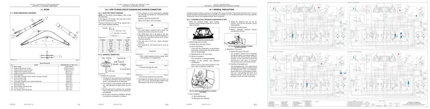
- Specifications, page 40: Issued 01-2006
- Diagram, page 128: CHAPTER 23 - ELECTRICAL SYSTEM
- Troubleshooting, page 488: CHAPTER 42 - TROUBLESHOOTING (HYDRAULIC SYSTEM)
- Foldout diagram (color), page 538: HYDRAULIC
Other manuals for this machine
Save 10% on 2 manuals, 15% on 3 or more. Other manuals for the E27 are listed below. Editions cover different serial number ranges: check the serial coverage and tick only the ones that match your machine.
Added to your cart. View cart
This is a service manual
Here's how it compares to the other manual types.
Service manual
Factory repair procedures and technical information such as specifications, troubleshooting, and wiring and hydraulic diagrams, for the models and systems the manual covers. See What's inside for its topics.
Operator's manual
Safe operation, controls, maintenance schedules, lubrication points, inspections, and basic checks. Repair procedures are in the service manual.
Parts manual
Illustrated diagrams with factory part numbers for identifying components and ordering parts. Repair procedures are in the service manual.
Engine service manuals are sometimes sold separately, since certain machine models were offered with more than one engine option.
What it's used for
Factory manual for in-house farm and construction shop use. Straightforward, complete, and easy to follow. It contains the OEM information dealership service departments and parts counters use to diagnose problems, identify components, and perform maintenance or repairs correctly.
Service shops and owner/operators who repair their own equipment
Identifying correct parts and seeing how assemblies come apart and go back together
Keeping equipment running with less downtime
Factory manual, 540 pages
Quantity one is the manual described above.
Fast free USA shipping
Ships in 1 business day.
60-day returns
Free if the mistake is ours. A manual ordered in error must come back unopened in its shrink-wrap; you pay return shipping and a 20% restocking fee applies. Return policy
Binder not included
Manuals over about 300 pages may need a standard 3-ring binder, which you can buy locally to keep the pages organized for shop use.
Questions about model, serial number, engine coverage or contents? Contact us before purchasing and we'll help confirm it's the right manual. Please verify the manual type, machine model, serial number range and engine coverage before purchasing: manuals ordered in error carry a 20% restocking fee (return policy).