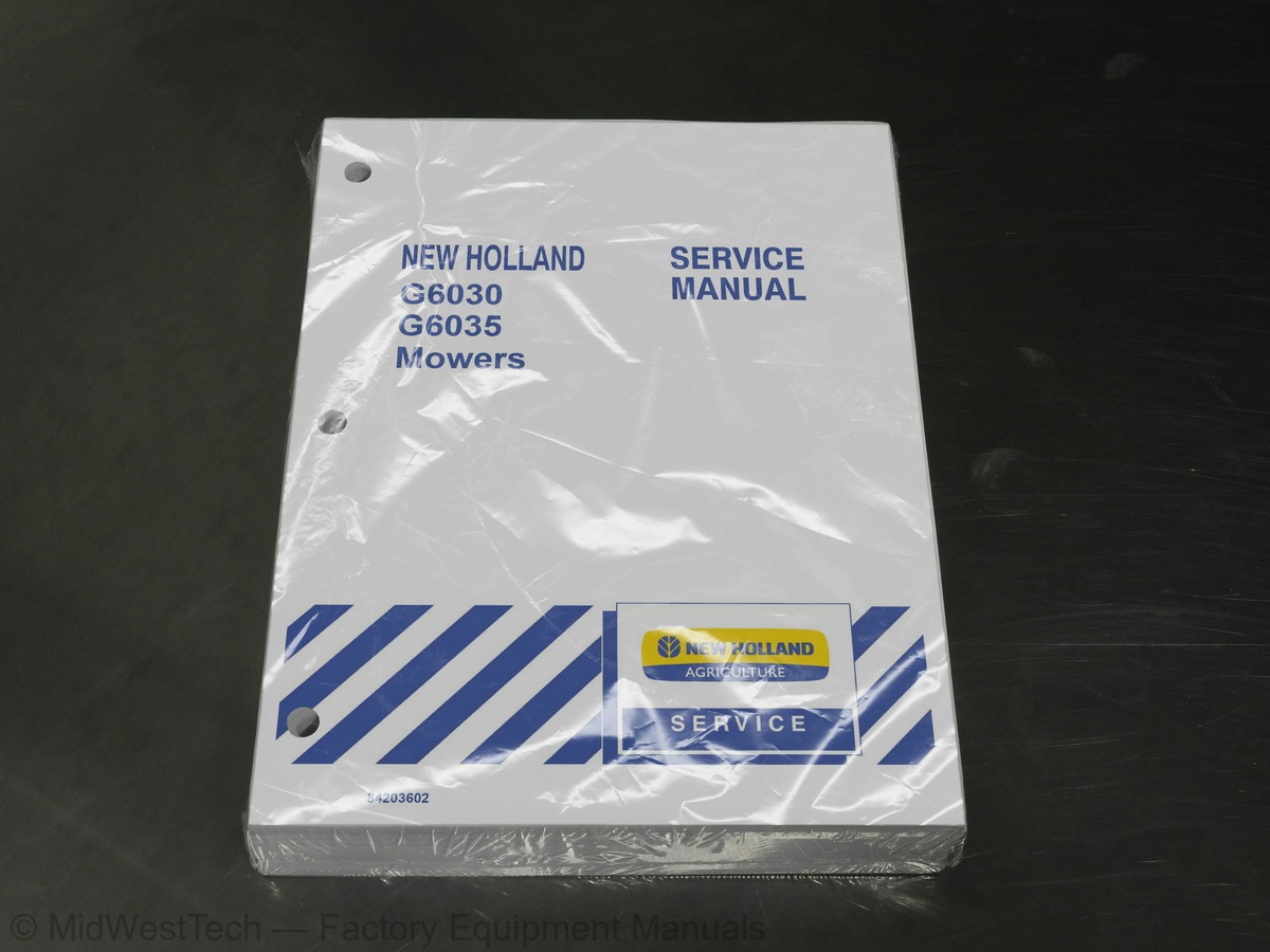
New Holland G6030, G6035 Mower Service Manual
799 pages · Publication 84203602
Added to your cart. View cart
What's inside
From the manual's own table of contents: 72 sections, 448 entries. See sample pages (PDF, 535 KB)
Technical Information -- Hardware6 topics
- General
- Plating
- Nut Tightening
- Locknuts
- Jam Nuts
- Thread Lubrication
Safety8 topics
- Commercial Mower
- Servicing the Commercial Mower
- Driving the Commercial Mower
- Operating the Power Take Off (PTO)
- Operating the Mower Deck
- Diesel Fuel
- Avoid High-pressure Fluids
- Safety
Show all 72 sections
Check and Adjust as Required17 topics
- Inoperative Service Checks
- Safety Items Checks
- Operative Service Checks
- General Engine Specifications
- Cylinder Block Specifications
- Cylinder Head Specifications
- Piston Specifications
- Piston Wrist Pin Specifications
- Piston Ring Specifications
- Connecting Rod Specifications
- Crankshaft Specifications
- Camshaft Specifications
- Valve Specifications
- Pushrod Specifications
- Rocker Arm Specifications
- Lubrication System Specifications
- Cooling System Specifications
Metric Bolt Torque Specifications -- All Models1 topic
- Compression Test
Description of Operation -- Engine2 topics
- Cylinder Block
- Cylinder Head and Valve Train Components
Overhaul -- Engine61 topics
- Engine
- Removal
- Fuel Injector and Glow Plug
- Valve Cover
- Oil Transfer Tube
- Water Pump Removal
- Rocker Arm, Support Bracket, and Pushrod
- Exhaust Manifold
- Engine Cylinder Head
- Lifter (Valve Tappet)
- Fuel Shutoff Solenoid
- Timing Gear Cover
- Timing Gears and Camshaft
- Oil Pan and Pick-up
- Connecting Rods, Bearings, and Piston
- Backing Plate and Oil Seal
- Front Crankshaft Gear
- Crankshaft and Main Bearings
- Cylinder Head
- Disassembly
- Inspection and Repair
- Valve Seats
- Valves
- Valve Guides
- Inspection and Replacement
- Valve Springs
- Rocker Arms
- Pushrods
- Assembly
- Inspection
- Pistons
- Disassembly and Inspection
- Piston Rings
- Connecting Rods
- Connecting Rod Bearing Oil Clearance Check
- Pistons, Rings, and Connecting Rod
- Main Bearing and Thrust Washer
- Removal And Inspection
- Crankshaft -- All Models
- Main Journal Number One Bearing (Bushing)
- Replacement
- Crankshaft Front Gear, Main Bearings and Thrust Washers
- Oil Pump Port Block
- Installation
- Timing Gear
- Camshaft
- Flywheel
- Timing Gear Housing
- Front Oil Seal and Steering Pump Seal
- Crankshaft and Bearing Holder
- Rear Oil Seal and Backing Plate
- Piston and Connecting Rod
- Oil Pick-up and Pan
- Camshaft and Timing Gear
- Oil Pump, Idler Gear, and Injection Timing
- Crankshaft Pulley
- Fuel Injection Pump
- Head Gasket Selection
- Valve Clearance Adjustment
- Water Pump
- Valve Cover/Air Intake
Description of Operation -- Engine Lubrication System8 topics
- Oil Filter
- Construction and Function
- Maintenance
- Oil Pump
- Installation and Adjustment
- Engine Oil Pressure Check
- Oil Pressure Relief Valve
- Oil Consumption
Description of Operation -- Cooling System5 topics
- Specifications
- Coolant
- Radiator Cap
- Thermostat
- Cooling Fan
Overhaul -- Cooling System1 topic
- Radiator
Injection Pump -- Description and Operation5 topics
- Fuel Variation Mechanism
- Delivery Valve Assembly
- CTD (Compact Timing Device) Mechanism
- Pumping Elements
- Delivery Valves
Overhaul10 topics
- Injection Pump
- Repair
- Spill-Timing and Governor Adjustments
- New Injection Pump or Drive Component
- Spill-Timing Procedure
- Fuel System Bleeding
- Automatic Bleeding
- Fuel Flow Chart
- Manual Bleeding
- Smoke Screw and High Idle Adjustment
Troubleshooting -- Governor System2 topics
- Governor
- Governor Adjustments
Description and Operation -- Fuel Injectors1 topic
- Fuel Filter and Shutoff Valve
Troubleshooting -- Fuel Injectors2 topics
- Injectors
- Assembly and Adjustment
Description of Operation -- Engine Breather Valve1 topic
- Engine Breather Valve
Troubleshooting -- Engine Breather Valve1 topic
- Rear to Front Axle Ration
Description of Operation5 topics
- Two-way (Sensitrack ™ ) Clutch
- Automatic Position -- Clutch Engaged
- Automatic Position -- Clutch Disengaged
- Fulltime FWD Position -- Clutch Locked
- Power Flow
Adjustment19 topics
- Rear Wheel Toe-In
- Rear Axle
- Drop Box
- Rear Axle and Differential
- 4WD Shift Shaft and Two-way (Sensitrack ™ ) Clutch
- Power Flow -- Range Gear
- Transaxle
- Rear Transmission
- Range Gear and Countershaft
- Main PTO Gear
- Side PTO Gear and Shaft
- Main Shaft and Fixed Main Gears
- Side PTO Gear
- Front Transmission
- Axle
- Differential
- Differential Lock
- Removal/Disassembly
- Assembly/Installation
Calibration2 topics
- Backlash
- Ring and Pinion Gear Tooth Contact Pattern
Description of Operation -- Hydrostatic Transmission2 topics
- Variable Displacement Pump Operation
- Fixed Displacement Motor Operation
Hydraulic Fluid Flow4 topics
- Neutral Position
- Forward Position
- Reverse Position
- Hydrostatic Transmission Filter
Pressure Testing19 topics
- High Pressure Relief
- Charge Pressure Relief
- Hydrostatic Transmission
- Hydrostatic Transmission Adjustment
- Directional Control Pedal Linkage
- HST Neutral Safety Switch
- PTO Removal
- Rear Transmission Disassembly
- Main PTO Gear Removal
- Side PTO Gear and Shaft Removal
- Rear Transmission Assembly
- Main PTO Gear Installation
- Side PTO Gear Installation
- PTO Clutch
- Automatic PTO Disengagement System
- PTO Control Lever Linkage
- PTO Disengagement Cable Adjustment
- Brake Discs
- Stators
Description of Operation -- Brakes2 topics
- Parking Brake
- Brakes
Brake Adjustment1 topic
- Free Travel
Description of Operation -- Hydraulic System16 topics
- Hydraulic System Priority/Flow Chart
- Hydraulic Fluid Filter
- Weight Transfer Valve
- Lift Control Valve
- Oil Flow
- Raise Position
- Lower and Float Position
- System Pressure Relief Valve
- Flow Restrictor
- Hydraulic Lift Cylinders and Lift Arms
- Hydraulic Fluid Cooler
- Hydraulic Lift Cylinders
- Hydraulic Lift Control Valve
- Hydraulic System Relief Valve
- Hydraulic System Restrictor Valve
- Lift Arms
Description of Operation -- Hydraulic Pump1 topic
- Hydraulic Pump
Description of Operation -- Remote Valves8 topics
- Single Acting -- Neutral
- Single Acting -- Spool Moved In
- Single Acting -- Spool Moved Out
- Double Acting -- Neutral
- Double Acting -- Spool Moved In
- Double Acting -- Spool Moved Out
- Hydraulic System Relief Valve Pressure Test
- Hydraulic System Relief Valve Pressure Adjustment
Description of Operation -- Power Steering System7 topics
- Power Steering Control Motor
- Check Valves
- Relief Valve
- Hydrostatic Transmission Charge Pump
- Hydraulic Fluid Filters
- Steering Cylinder
- Steering Column and Wheel
Description of Operation -- Oil Flow10 topics
- Oil Flow – Neutral Operation
- Oil Flow – Left Turn
- Oil Flow – Right Turn
- Oil Flow – Manual Operation
- Steering System Relief Pressure
- Steering Cylinder Test
- Lubrication
- Power Steering Motor
- Steering Column
- Removal and Disassembly
Wheels and Tires1 topic
- Wheel Tread Settings
Mower Weighting3 topics
- Liquid Ballast
- Front Wheel Weights
- Rear Weights
Wheel Bolt Torque6 topics
- Torque
- Front Wheel Torque
- Rear Wheel Torque
- Description
- Component Location and Function
- Main Ground Locations
Electrical System Components - Description and Testing62 topics
- Battery
- Checking the Battery Electrolyte Level
- Battery Removal
- Battery Installation
- Fusible Link
- Fuse Block
- Key Switch
- Description and Location
- Key Switch Troubleshooting -- Continuity Test
- Accessory/Run Position
- Heat Position
- Start Position
- Key Switch Troubleshooting -- Connector Wiring
- Light Switch
- Light Switch Troubleshooting -- Continuity Test
- Headlight
- Seat Safety Start Switch
- Seat Safety Start Switch Troubleshooting -- Continuity Test
- PTO Safety Start Switch
- PTO Safety Start Switch Troubleshooting - Continuity Test
- Hydrostatic Transmission Safety Start Switch
- Adjustment
- HST Safety Start Switch Troubleshooting - Continuity Test
- Park Brake Safety Start Switch
- Park Brake Safety Start Switch Troubleshooting -- Continuity Test
- Master Brake Safety Start Switch
- Master Brake Safety Start Switch Troubleshooting -- Continuity Test
- Relays
- Brake Relay Functions
- Relay Identification
- Relay Testing
- Brake Relay Testing
- Diodes
- Diode Identification
- Diode Testing
- Glow Plug Indicator Light Timer
- Glow Plug Indicator Light Timer Operation Testing
- Seat Safety Switch Timer
- Seat Safety Switch Timer Operation Testing
- Engine Oil Pressure and Overheat Warning Alarm
- Warning Alarm Testing
- Engine Glow Plugs
- Engine Glow Plug Testing
- Engine Oil Pressure Switch
- Engine Oil Pressure Switch Testing
- Engine Coolant Temperature Switch (Warning Alarm)
- Engine Coolant Temperature Switch Testing
- Engine Coolant Temperature Sending Unit (Temperature Gauge)
- Engine Coolant Temperature Sending Unit Testing
- Air Filter Restriction Switch
- Air Filter Restriction Switch Testing
- Fuel Shutoff Solenoid Testing
- Fuel Level Sending Unit
- Fuel Level Sending Unit Testing
- Electric Fuel Pump
- Electric Fuel Pump Testing
- Auxiliary Power Outlet
- Auxiliary Power Outlet Testing
- Electric Cruise Control Switch (Optional)
- Cruise Control Switch Testing
- Cruise Control Magnet (Optional)
- Cruise Control Magnet Testing
Complete Electrical System Wiring Diagram13 topics
- Safety Start Circuit
- Operator Presence Circuit
- Engine Stop Circuit (Operator Removed From Seat)
- Engine Glow Plug Circuit
- Lighting Circuit
- Engine Coolant Temperature and Alarm Circuit
- Engine Oil Pressure and Alarm Circuit
- Fuel Level Circuit
- Park Brake Indicator Light Circuit
- Air Filter Restriction Warning Light Circuit
- Hour Meter Circuit
- HST Electronic Cruise Control Circuit (Optional)
- Charging Circuit
Instrument Panel -- Component Operation and Servicing6 topics
- Instrument Panel Connector
- Instrument Panel Removal
- Instrument Panel Light Replacement
- Fuel Gauge Testing
- Temperature Gauge Testing
- Instrument Panel Installation
Charging System27 topics
- Description and Operation
- Alternator
- Principle of IC Regulator
- Alternator Specifications
- Alternator Troubleshooting
- No Charging
- Insufficient Charging
- Overcharge
- Unstable Charging Circuit
- Abnormal Noise of Alternator
- Preliminary Alternator Tests
- Alternator Drive Belt
- Alternator Output
- Alternator Removal
- Alternator Components
- Alternator Disassembly
- Alternator Component Testing and Inspection
- Stator
- Rotor
- Rectifier Assembly
- Alternator Brushes
- Alternator Bearings
- Drive Pulley
- Alternator Frames
- Alternator Assembly
- Alternator Bench Check
- Alternator Installation
Starting System for G6030 Mowers21 topics
- Description of Operation
- Starter Motor Assembly
- Starter Solenoid
- Pinion Clutch
- Starter Motor Specifications - G6030
- Starter Motor Troubleshooting - G6030
- Pinion Shaft Fails to Advance
- Pinion Motor Rotates But No Rotation Transmitted to Engine
- Motor Rotates Before Pinion Meshes With Ring Gear
- Pinion Meshes With Ring Gear But Starting Motor Fails to Turn
- Motor Fails to Stop After Engine Starts and Key Switch Is Turned Off
- Starter Motor Removal
- Starter Motor Disassembly
- Starter Motor Inspection
- Starter Motor Electrical Testing
- Armature
- Brush Holder
- Starter Components
- Pinion Position Adjustment
- Starter Motor No Load Test
- Starter Motor Installation
Starting System for G6035 Mowers3 topics
- Starter Motor Specifications - G6035
- Starter Motor Troubleshooting - G6035
- Field Coil
Platform7 topics
- Engine Cover
- Fenders
- Seat Belt / Seat/ Seat Deck
- Roll Over Protective Structure (ROPS)
- Fuel Tank
- Fuel Usage Safety
- Operator Deck
Inside this manual
Real pages from this service manual (799 pages). Open the sample pages (PDF, 534 KB)
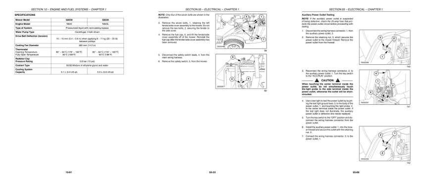
- Specifications, page 154: SECTION 10 -- ENGINE AND FUEL SYSTEMS -- CHAPTER 1
- Repair procedure, page 598: SECTION 55 -- ELECTRICAL -- CHAPTER 1
- Diagram, page 634: SECTION 55 -- ELECTRICAL -- CHAPTER 1
Other manuals for this machine
Save 10% on 2 manuals, 15% on 3 or more. Other manuals for the G6030, G6035 are listed below. Editions cover different serial number ranges: check the serial coverage and tick only the ones that match your machine.
Added to your cart. View cart
This is a service manual
Here's how it compares to the other manual types.
Service manual
Factory repair procedures and technical information such as specifications, troubleshooting, and wiring and hydraulic diagrams, for the models and systems the manual covers. See What's inside for its topics.
Operator's manual
Safe operation, controls, maintenance schedules, lubrication points, inspections, and basic checks. Repair procedures are in the service manual.
Parts manual
Illustrated diagrams with factory part numbers for identifying components and ordering parts. Repair procedures are in the service manual.
Engine service manuals are sometimes sold separately, since certain machine models were offered with more than one engine option.
What it's used for
Factory manual for in-house farm and construction shop use. Straightforward, complete, and easy to follow. It contains the OEM information dealership service departments and parts counters use to diagnose problems, identify components, and perform maintenance or repairs correctly.
Service shops and owner/operators who repair their own equipment
Identifying correct parts and seeing how assemblies come apart and go back together
Keeping equipment running with less downtime
Factory manual, 799 pages
Quantity one is the manual described above.
Fast free USA shipping
Ships in 1 business day.
60-day returns
Free if the mistake is ours. A manual ordered in error must come back unopened in its shrink-wrap; you pay return shipping and a 20% restocking fee applies. Return policy
Binder not included
Manuals over about 300 pages may need a standard 3-ring binder, which you can buy locally to keep the pages organized for shop use.
Questions about model, serial number, engine coverage or contents? Contact us before purchasing and we'll help confirm it's the right manual. Please verify the manual type, machine model, serial number range and engine coverage before purchasing: manuals ordered in error carry a 20% restocking fee (return policy).