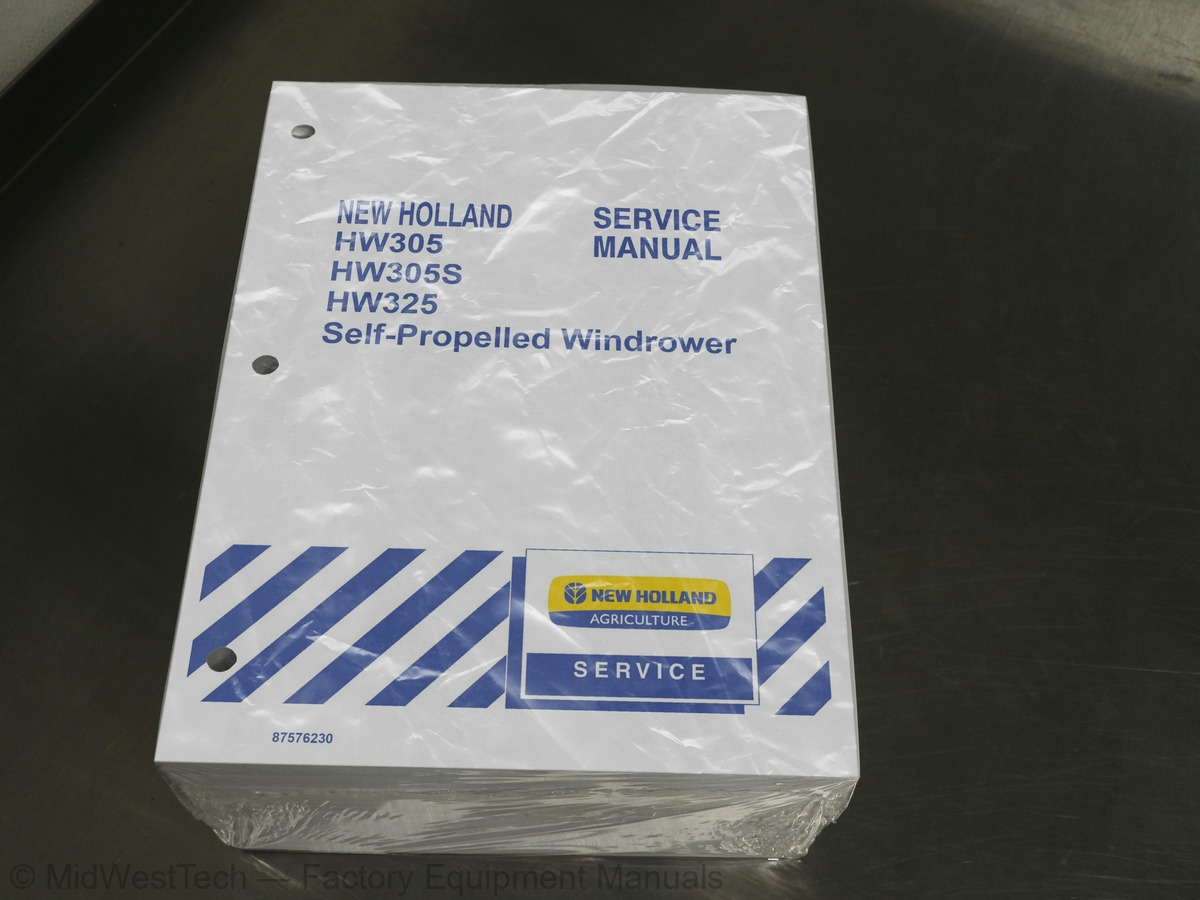
New Holland HW305, HW305S, HW325 Self-Propelled Windrower Service Manual
2,031 pages · Publication 87576230
Added to your cart. View cart
- Models
- HW305, HW305S, HW325 Self-Propelled
- Manual type
- Service Manual
- Pages
- 2,031
- Publication
- 87576230
- Condition
- Brand new
What's inside
From the manual's own table of contents: 406 sections, 700 entries. See sample pages (PDF, 615 KB)
Show all 406 sections
Engine1 topic
- Removal
Block1 topic
- Inspection
Oil Pump Gear2 topics
- Inspection, Removal, and Installation
- Installation for Inspection
Camshaft Bushings1 topic
- Inspection and Installation
Piston2 topics
- Disassembly
- Assembly
Bushings1 topic
- Rod Markings
Piston Rings1 topic
- Installation
Piston and Rod Assembly1 topic
- Installation for Clearance
Rod Bearing2 topics
- Clearance
- Height Measurement
Valve Seals1 topic
- Inspection/Installation
Valves2 topics
- Specifications
- Valve Stem Play
Valve Springs1 topic
- Inspection of the Intake and Exhaust Valve Springs
Push Rods1 topic
- Rocker Arm Group
Timing Gearbox1 topic
- Timing
Injectors2 topics
- Reinstallation
- Bleeding
Fuel Tanks1 topic
- Install
Primary (Outer) Air Filter2 topics
- Cleaning With Air
- Cleaning By Washing
Oil Specification1 topic
- Repair
Motors2 topics
- Fixed Displacement Motor
- Variable Displacement Motor
Oil Flow2 topics
- Neutral
- Forward/Reverse
Solenoid Valve (2-Speed Drive Motor Only)2 topics
- Low-Range Operation
- High-Range Operation
Relief Valve1 topic
- Operation
Overheating Transmissions1 topic
- Loss of Propulsion
Pressure Testing3 topics
- Port Locations
- Charge Pressure (HW305/305S)
- Charge Pressure (HW325)
Charge Pressure System Test2 topics
- Tandem Pump Charge Pressure Test
- Complete Charge System Test (HW325 Only)
High Pressure Relief Valve Test6 topics
- Gage Port and Relief Valve Locations
- Pressure Port Locations
- Case Pressure Test (Pump)
- Case Pressure Test (Motor, HW325 only)
- Suction Test
- Case Flow Test (HW325 Only)
Ground Speed Circuit (HW305/305S)2 topics
- Troubleshooting
- Ground Speed Display Does Not Function (HW305/305S)
Ground Speed Circuit (HW325)1 topic
- Ground Speed Display Does Not Function (HW325)
Troubleshooting Charts4 topics
- Windrower Will Not Shift into High Range
- Windrower Will Not Shift into Low Range
- Charge Pump
- Hydrostatic System
Explanation of Terms Used in Failure Analysis4 topics
- Lack of Lubrication
- Operating at Excessive Temperature Levels
- Cavitation
- Overspeeding of the Unit
Parts Worn or Scored From Contamination2 topics
- Abrasive Contaminants
- Plates Scored from Water in Oil (Non-Particle Contaminants)
Tandem Pump11 topics
- Rear Half Port Breakdown
- Front Half Port Breakdown
- Shaft Seal Replacement
- Charge Pump Removal
- Charge Pump Inspection
- Charge Pump Assembly
- O Ring Seals
- Trunnion Seal (Control Shaft Side)
- Trunnion Cover (Plain)
- Tandem Pump Removal
- Tandem Pump Installation
Ground Drive Motor1 topic
- Inspection/Parts Breakdown
Pintle Arm Rotary Potentiometer (R21)1 topic
- Testing
Propulsion Rotary Potentiometer (R21)2 topics
- Neutral Adjustment
- Theory of Operation
Ground Drive1 topic
- Circuit Diagrams
Control Valve Manifold (HW305/305S/325)2 topics
- Service Parts
- Valve Identification Codes
HW305/305S Component Identification and Location6 topics
- Right-hand (RH) View
- Plan View
- Front View
- Rear View
- Bottom View
- Left-hand (LH) View (Hidden Against Mounting Plate)
Auxiliary Control Manifold1 topic
- Component Identification and Location
Header Control Valve Manifold (HW305/305S)1 topic
- Top View
Header Control Manifold (HW325)1 topic
- HW325 Component Identification and Location
Main Control Manifold Valves7 topics
- Two-way Two-position (Normally Closed) Poppet Valves
- Three-way Two-position Spool Valve
- Two-way Two-position (Normally Open) Poppet Valve
- (Normally Open) Pressure Reducing/Relieving Valves
- (Normally Open) Solenoid-operated Relief Valves
- (Normally Closed) Solenoid-operated Proportional Flow Control
- Replacement
Cartridge Valves (Non-solenoid-operated)3 topics
- Direct-acting Flow Control Needle Valve
- Pilot-operated Relief Valve
- Differential-Pressure-Sensing Valve
Needle Valve (AD) and Piloted Relief Valves1 topic
- Adjustment
Start-up Procedure1 topic
- Cooling Circuit Bypass Pressure
General5 topics
- Reduced System Pressure
- Reduced Hydraulic Flow
- Excessive Noise
- Overheating
- Power Loss
Parts Evaluation4 topics
- Discoloration
- Scratches or Grooves
- Rework
- Repeat Failures
Service Techniques5 topics
- General
- Oil Level
- Hoses and Tubes
- O Ring Flat Face Seal Fittings
- O Ring Flat Face Seal Fitting Torque Values
Hydraulic Reservoir Replacement -- HW305 and HW305S1 topic
- Tank Preparation (Plastic Tanks only)
Refrigerant Ingredients2 topics
- Lubricants
- Refrigerant (R134a)
Expansion Valve3 topics
- Description
- Valve Components
- Port Identification
Switches and Controls2 topics
- Air Conditioner Temperature (Thermostatic) Control Switch
- Blower Fan Switch
Compressor Protection Switches2 topics
- High-pressure Cutout Switch (S-40)
- Low-pressure Cutout Switch (S-69)
Preliminary Troubleshooting and Testing1 topic
- Operational Checks
Diagnosis Charts -- Air Conditioning System2 topics
- Test Procedure: Stabilizing the System
- Test Ports
Pressure/Temperature Relationships2 topics
- Leak Testing
- Refilling
Contaminants1 topic
- Preventing Mixing of Service Equipment
Refrigerant Extraction and Recycling Equipment3 topics
- Using Extraction Equipment
- Using Recycled Equipment
- Recycling vs. Reclaiming
Containment of Air Conditioning Refrigerants7 topics
- Recovery
- Flushing
- Recharging/Refilling
- Using a Manifold Gauge Set
- Checking Refrigerant for Excess Air
- Containers for Storing Recycled Refrigerant
- Disposal of Empty of Near-Empty Disposable Containers
Overhaul -- Air Conditioning System1 topic
- Inspection and Repair
Clutch and seal replacement2 topics
- Inspection and Assembly
- Chapter 2 - Climate Control
Air Conditioning Filters1 topic
- Removal/Replacement
Control Panel – Manual Temperature Control -- (A-05)1 topic
- Temperature Control Switch
Diagnosis Charts – Air Conditioning System1 topic
- Disposal of Empty or Near-Empty Disposable Containers
Compressor and Clutch2 topics
- Checking Compressor Oil for Contamination
- Adding Compressor Oil
Clutch Procedures6 topics
- Clutch Run-In
- Clutch Test
- Clutch Removal
- Clutch Inspection
- Clutch Installation
- Electrical Connection
Electrical Terms and Equipment1 topic
- Definition
Rocker Switches1 topic
- Momentary Rocker Switches
Circuit Breakers1 topic
- Location of Circuit Breakers
Fuses1 topic
- Fuse Panel Identification Tables
Basic Circuitry/Component Testing4 topics
- Continuity Test for Open Circuits
- Continuity Test for Short to Ground
- Resistance Test for Electrical Components
- Measuring Voltage
Diodes1 topic
- Test Procedure
Electro-hydraulic Solenoid Valve Coils1 topic
- Operational Check
Fuses, Relays and Switches1 topic
- Switch and Relay Contacts
Wire Harness Identification2 topics
- Wire Color Codes
- Primary Harness Connectors
HW305S Models4 topics
- Selectable Functions Monitoring
- Operating Mode
- Configuration Mode
- Warning Mode
Configuration Mode1 topic
- System Monitoring -- HW305/305S Models
Function Monitoring, Machine Configuration, and Diagnostics Menus -- HW325 Models6 topics
- Machine Configuration/User Setup Menu
- Critical Warning Displays -- Automatic Shutdown
- Critical Warning Displays -- No Shutdown
- Non-Critical Warning Displays
- Electrical Fault Codes
- System Monitoring -- HW325
Power Distribution – HW305/305S1 topic
- Introduction
Air Conditioning Systems1 topic
- General Principles of Operation (Manual and ATC Systems)
General Operation5 topics
- Heater Operation
- Heater Operation – Sequence of Events
- Defrosting/Defogging Operation
- Air Conditioner (A/C) Operation
- Ventilation
System Component Functions12 topics
- Automatic Fan Speed Control (AUTO)
- Manual Mode Fan Speed Control (Up/Down)
- A/C Compressor Clutch Control
- Heater Water Valve
- Cab Air Temperature Sensor
- Evaporator Probe
- ATC HVAC Component Usage
- Fault Codes
- Advanced Diagnostics Display Mode
- Revision Level
- Setting Parameters
- ATC Troubleshooting Quick-Checks
Exit Lighting (Left Side Stubble Light)2 topics
- Functional Check
- Procedure
General Information2 topics
- Engine Functions for the XCM
- Starting Circuits
Coolant Temperature Circuit2 topics
- 4-Line Display -- Engine Coolant Temperature Scale
- A-Pillar Display -- Engine Coolant Temperature Scale
Cold-Start Injection Advance Circuit (KSB)1 topic
- Fuel Injection Pump Harness Connections
Battery2 topics
- Size and Rating
- How a Battery Works
Battery Troubleshooting4 topics
- Determining the Cause of Failure
- Application and Installation
- Service History
- Visual Inspection
Testing The Battery -- General2 topics
- Key Off” Current Drain
- Voltage Drop Test
Charging the Battery5 topics
- Determining Battery Charge Procedure
- Slow Charge Procedure: For Batteries with Charges Below 11.0V
- Selecting Battery Charging Method
- Slow Charge Procedure
- Battery Charging Precautions
Alternator11 topics
- Charging System Excitation Circuit Operation
- Alternator and Voltage Regulator
- Maintaining the Alternator
- Alternator Connections
- Alternator and Voltage Regulator Precautions
- Alternator Belt
- Belt Removal/Replacement
- Welding On the Machine
- Testing the Alternator
- Alternator Removal
- Alternator Installation
Inputs9 topics
- Engine Inputs
- Fuel Inputs
- Header Inputs
- Hydraulics Inputs
- Lights Inputs
- Preheat Inputs
- Propulsion Inputs
- PTO Inputs
- Reel Inputs
Outputs3 topics
- Header Outputs
- HVAC Outputs
- Preheat Outputs
Audible Warnings3 topics
- Critical Warnings – Automatic Shutdown
- Critical Warnings – No Shutdown
- Non-Critical Warnings
Audible Alarm Priorities3 topics
- Low Priority Warnings
- Medium Priority Warnings
- High Priority Warnings
SPN/FMI Code Charts2 topics
- FMI Codes
- SPN Codes
Engine Fault Codes4 topics
- FAULT CODE -- 101-03 Oil Pressure Switch Shorted to High Source
- FAULT CODE -- 101-04 Oil Pressure Switch Shorted to Low Source
- FAULT CODE -- 102-03 Air Filter Restriction Switch Shorted to High Source
- FAULT CODE -- 104-04 Engine Coolant Temp Sensor Shorted to Low Source
Hydraulic Fault Codes1 topic
- Shorted to High Source
Propulsion Fault Codes33 topics
- FAULT CODE -- 404-03 MFH Position Sensor Shorted to High Source
- FAULT CODE -- 404-04 MFH Position Sensor Shorted to Low Source
- FAULT CODE -- 404-14 MFH Position Sensor Special Instructions
- FAULT CODE -- 405-03 Pintle Arm Position Sensor Shorted to High Source
- FAULT CODE -- 405-04 Pintle Arm Position Sensor Shorted to Low Source
- Shorted to Low Source
- and Pot B Needs Calibration
- FAULT CODE -- 408-03 MFH Neutral Switch Shorted to High Source
- FAULT CODE -- 408-07 MFH Neutral Switch Mechanical Out of Range
- FAULT CODE -- 409-03 Park Brake Switch Shorted to High Source
- Needs Calibration
- FAULT CODE -- 418-03 MFH Position Sensor Shorted to High Source
- FAULT CODE -- 418-04 MFH Position Sensor Shorted to Low Source
- FAULT CODE -- 418-13 MFH Position Sensor Needs Calibration
- FAULT CODE -- 419-03 MFH Position Sensor Shorted to High Source
- FAULT CODE -- 419-04 MFH Position Sensor Shorted to Low Source
- FAULT CODE -- 419-07 MFH Position Sensor Mechanical Out of Range
- FAULT CODE -- 419-13 MFH Position Sensor Needs Calibration
- FAULT CODE -- 420-03 MFH Position Sensor Shorted to High Source
- FAULT CODE -- 420-04 MFH Position Sensor Shorted to Low Source
- FAULT CODE -- 420-07 MFH Position Sensor Mechanical Out of Range
- FAULT CODE -- 420-13 MFH Position Sensor Needs Calibration
- FAULT CODE -- 421-03 MFH Position Sensor Shorted to High Source
- FAULT CODE -- 421-04 MFH Position Sensor Shorted to Low Source
- FAULT CODE -- 421-13 MFH Position Sensor Needs Calibration
- FAULT CODE -- 424-13 Propulsion Forward Coil Needs Calibration
- FAULT CODE -- 425-13 Propulsion Forward Coil Needs Calibration
- FAULT CODE -- 426-13 Propulsion Reverse Coil Needs Calibration
- FAULT CODE -- 427-13 Propulsion Reverse Coil Needs Calibration
- FAULT CODE -- 431-03 MFH Position Sensor R-18 Shorted to High Source
- FAULT CODE -- 432-03 MFH Position Sensor R-18 Shorted to High Source
- FAULT CODE -- 433-03 Propulsion Cylinder Shorted to High Source
- FAULT CODE -- 434-03 Propulsion Cylinder Shorted to High Source
PTO Fault Codes1 topic
- FAULT CODE -- 200-12 Header Speed Sensor Bad Intelligent Device
Standard Wiring Harnesses (HW305/305S)8 topics
- FM Harness (Front)
- FM Harness (Rear)
- FM Harness (Engine LH)
- FM Harness (Engine RH)
- LL and RL Harnesses (Lighting)
- CM Harness (RH Console)
- CA Harness (Roof)
- SC Harness (Steering Column)
Standard Wiring Harnesses (HW325)4 topics
- CM Harness (Electrical Panel)
- CM Harness (Inside Cab)
- CM Harness (Seat and Right Hand Console)
- OR Harness (Outside Roof)
Inside this manual
Real pages from this service manual (2,031 pages). Open the sample pages (PDF, 615 KB)

- Specifications, page 84: SECTION 00 - GENERAL INFORMATION - CHAPTER 1
- Troubleshooting, page 1,169: SECTION 55 - ELECTRICAL SYSTEMS - CHAPTER 11
- Diagram, page 1,479: SECTION 55 -- ELECTRICAL SYSTEMS -- CHAPTER 13
- Color page, page 1,060: SECTION 55 -- ELECTRICAL SYSTEMS -- CHAPTER 5
This is a service manual
Here's how it compares to the other manual types.
Service manual
Factory repair procedures and technical information such as specifications, troubleshooting, and wiring and hydraulic diagrams, for the models and systems the manual covers. See What's inside for its topics.
Operator's manual
Safe operation, controls, maintenance schedules, lubrication points, inspections, and basic checks. Repair procedures are in the service manual.
Parts manual
Illustrated diagrams with factory part numbers for identifying components and ordering parts. Repair procedures are in the service manual.
Engine service manuals are sometimes sold separately, since certain machine models were offered with more than one engine option.
What it's used for
Factory manual for in-house farm and construction shop use. Straightforward, complete, and easy to follow. It contains the OEM information dealership service departments and parts counters use to diagnose problems, identify components, and perform maintenance or repairs correctly.
Service shops and owner/operators who repair their own equipment
Identifying correct parts and seeing how assemblies come apart and go back together
Keeping equipment running with less downtime
Factory manual, 2,031 pages
Quantity one is the manual described above.
Fast free USA shipping
Ships in 1 business day.
60-day returns
Free if the mistake is ours. A manual ordered in error must come back unopened in its shrink-wrap; you pay return shipping and a 20% restocking fee applies. Return policy
Binder not included
Manuals over about 300 pages may need a standard 3-ring binder, which you can buy locally to keep the pages organized for shop use.
Questions about model, serial number, engine coverage or contents? Contact us before purchasing and we'll help confirm it's the right manual. Please verify the manual type, machine model, serial number range and engine coverage before purchasing: manuals ordered in error carry a 20% restocking fee (return policy).