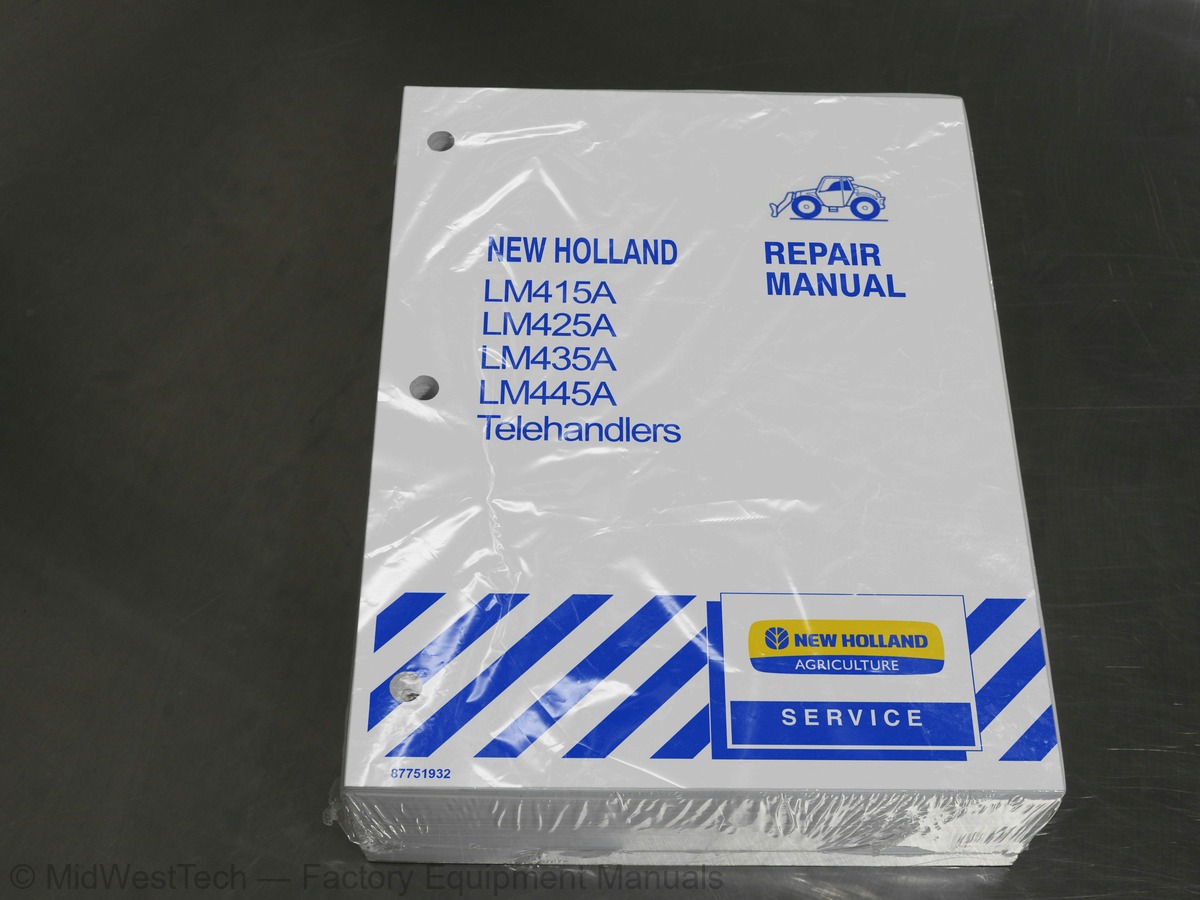
New Holland LM415A, LM425A, LM435A, LM445A Telehandler Service Manual
945 pages · Publication 87751932
Added to your cart. View cart
- Models
- LM415A, LM425A, LM435A, LM445A
- Manual type
- Service Manual
- Pages
- 945
- Publication
- 87751932
- Condition
- Brand new
What's inside
From the manual's own table of contents: 55 sections, 538 entries. See sample pages (PDF, 384 KB)
SECTION 50 - CAB ENVIRONMENT12 topics
- Notes For Spare Parts
- How to Move the Vehicle with the Battery Removed
- Engine 0.0
- Electrical Systems
- Hydraulic Systems 2.0.0
- Removal and Installation 2.0.0
- Vehicle Product Identification Number
- Vehicle Identification Plate
- Engine Identification 2.0.6
- Transmission Identification 4x4 Power Shuttle
- Rear Axle Identification
- Identification Plates in the Cab
Important Ecological Considerations1 topic
- PrecautionS 20
Service Techniques3 topics
- General
- Hoses and TUDES
- ‘O’ Ring Flat Face Seal Fittings
Minimum Hardware Tightening TorqueS6 topics
- Front AXle
- Rear Axle
- Weight of Machines
- Lubricants and Coolants
- Four Wheel Drive Tire Combinations
- Tire PreSSUES 6
Tool Listing and Applications5 topics
- Transmission Powershift
- Hydraulic Systems 2.0.0
- Telescopic BOOM
- Electrical System 2.2
- Engine 2
Telescopic BOOM 12 topics
- Assembly Dimensions
- Calibration Test Conditions
of Bosch Injection Pump Type VE 4/12 F 1100 L9541 topic
- Calibration Test Conditions
Overhaul 666 topics
- Coding of Source Engines - F4GE0454C - F4GE0484G
- Checks, Measurements and Repairs
- CrankCaSe 0.0
- Crankshaft 2.2.0
- Connecting Rods
- Oil Filter
10 246 14 Bosch Injection PUMP5 topics
- Removal
- ASSOMDIY 20
- Coolant PUMP
- Removal
- Installation
Show all 55 sections
Description and Operation6 topics
- Gear Shift Mechanism
- Transmission Oil Supply Ports
- Transmission Oil Flow Through Solenoid Valve
- Oil Flow Solenoid Control Valve Operation (Forward Drive Only Shown)
- Transmission Hydraulic Valves and Pressure Test Points
- Transmission Power FIOWS
Fault Finding 0.02 topics
- Stall Procedure 06
- Stall Speed 2
Overhaul27 topics
- Forward / Reverse Control Solenoid Valve
- Solenoid Valve
- Disassembly
- Re-assembly
- Transmission Overview
- Gear Train one e ete t teen ete nee
- Removal
- Disassembly
- Rear Output Shaft End
- Input Shaft 2
- Disassembly
- Rear Support End
- Front Support End
- Rear Support End
- Oil Pump Drive Shaft Support Bearing
- Reverse Idler Shaft
- TrAnsSMiSSION
- Gear Train End Float
- Shimming Procedure
- Rear Cover Attachment
- Gear Shift Selector Assembly
- Spin On Oil Filter 2
- Powershuttle Transmission Wiring Diagram
- Wire Colors 0.0
- Transmission Control
- Direction Changes
- Common Connection Between Microprocessor and Control Valves
Troubleshooting4 topics
- Input Test 2.0.6
- Speed Sensor Test Using the Turbine Speed Display
- Output Test 2.0
- Output Test - Fault by LED Number
Description of Operation43 topics
- Transmission Control
- Torque Converter
- Transmission Hydraulic System
- Hydraulic Oil FIOWS 1.0.6
- Modulation Valve Operation
- DiagraMA . 1
- Diagram Ba
- Diagram Co
- DiagraM D
- Diagram Eo
- Diagram Fo
- Diagram Gow. eet eee
- Pressure Testing Clutch and High Pressure Circuit
- Pressure Testing Torque Converter and Cooler Circuit
- Port 1 System Pressure 0.0
- Port 2 Oil cooler In
- Transmission / Engine
- REMOVAl 6.0
- Separating Engine from Transmission
- Modulation Valve Removal
- Disassembly and Assembly of the A and B Clutches
- A” Clutch Disassembly
- A” Clutch Reassembly
- B” Clutch Reassembly
- Disassembly and Assembly of C and D Clutches and Shaft
- C” Clutch Disassembly
- D” Clutch Disassembly
- Disassembly and Assembly of the E and F Clutch Packs
- E” Clutch Reassembly
- F’ Clutch Reassembly
- Regulator Valve Disassembly
- Modulator Valve
- Disassembly
- Reassembly
- Manifold Plate 20
- Reassembly
- Transmission Oil Cooler
- Thermostatic Switch Replacement
- Electric Fan Assembly Replacement
- Oil Cooler Radiator Assembly Replacement
- Transmission Oil Cooler Electrical System
- Center Bearing
- Replacement
Description of Operation33 topics
- Axle REMOVEd .. 16. cette ttt ttt tet teeeeeeeee
- Axle Removal Procedure
- Planetary Reduction Assembly and Wheel Hubs
- Steering Rod End Ball Joint Removal
- Swivel Housing Removal
- Handbrake LOCK 0
- Shaft Retaining Lock Nuts
- Axle Shaft Removal
- Swivel Pin Bearing Removal
- Removal of Lower Swivel Pin Bearing Cone
- Removal of Shaft Bearing and Seal Housing
- Reduction Hub, Swivel Housing and Axle Shaft Reassemble
- Hub Oil Seal Installation
- Swivel Housing Seal Installation
- Swivel Pin Bearing Cone Installation 2.0.0.0
- Lower Swivel Pin Bearing Cone Installation
- Steering Cylinder Removal
- Steering Cylinder Disassembly
- Transfer Gearbox Disassembly
- Axle Trumpet Housing Removal
- Differential Assembly Removal
- Differential Disassembly
- Disassembly
- Differential Preload «2.0
- Load Sensor 1.1
- Component Overhaul
- Axle Removal Procedure
- Brake Master Cylinder .. 2.0.0.0
- Brakes Applying
- Brakes Applied
- Brake Bleeding Procedure
- Machine Preparation
- Servo Circuit Pressure Testing
Overhaul26 topics
- Brake Master Cylinder
- Removal
- Installation
- Master Cylinder Overhaul
- ASSOMDIY 20
- Push Rod Components
- Servo HOUSING
- Brake Piston
- Return Spring & Feed Valve Assembly
- Fluid Feed Valve Replacement
- Rear Axle Brake Disassembly
- Brake Piston Assembly
- Parking Brake Operation
- Handbrake Adjustment
- Handbrake Lever
- Front Axle 2.0.0
- Adjustment Procedure
- Introduction 1
- Hydraulic Control Valves 0.20
- Hydraulic PUMP
- Flow Divider Valve
- Pressure Reducing Valve and Accumulator
- Pressure Reducing Valve Operation
- Hydraulic Control Valves 0.0.0
- Circuit Relief Valves
- Control Buttons Released
Fault Finding and Pressure Testing12 topics
- Flow Testing (Using Auxiliary Test Hydraulic Ports)
- Pressure Testing (Using Auxiliary Test Hydraulic Ports)
- Using Auxiliary Test Hydraulic Ports 2.0
- Telescopic Circuit Relief Valve Pressure Test
- Tilt Cylinder Pressure Testo
- Piston End Circuit Relief Valve
- LIft Cylinder Circuit Relief Valves Pressure Test
- Pressure Testing (Using Control Valve Test Port)
- Preparation 2.0.0
- Piston End Circuit Relief Valve
- Boom Lift Cylinder Circuit Relief Valve Pressure Test
- Adjustment of Circuit Relief Valves 2.0.0.0
Component Overhaul7 topics
- Hydraulic Control Valve
- Removal and Installation
- Disassembly 0.0.0.0
- Disassembly
- Inspection 2
- Re-Assembly 2.1.2
- Solenoid Control Valves 1.0
Description and Operation16 topics
- Introduction 2.00
- Hydraulic Control Valves
- Counterbalance Valves
- Hydraulic Oil Cooler
- Cooler Bypass Valve . 0.0
- Hydraulic Oil Filters and Screen
- Component Operation
- Hydraulic PUMP
- Flow Divider Valve
- Pressure Reducing Valve and Accumulator
- Pressure Reducing Valve Operation
- Solenoid Control Valves 2.1
- Inlet End Housing
- Control Valve GallerieS
- Single Cylinder Operation
- Circuit Relief Valve Components
Fault Finding and Pressure Testing1 topic
- Fault Finding
Troubleshooting14 topics
- Flow and Pressure Testing
- Preparation 2.0
- Flow Testing (Using Auxiliary Boom Hydraulic Ports)
- Pump Cavitation Test 00
- Performance Test 1.0
- Relief Valve Locations
- System Pressure Test
- Telescopic Cylinder Relief Valve 0.0.0
- Circuit Relief Valve Adjustment
- Tilt Cylinder Relief Valves 1.0.0
- Boom Lift Cylinder Relief Valve
- Servo Hydraulic Circuit Pressure Test
- Valve Components
- Proportioning Valve Module Replacement
Overhaul35 topics
- Component Overhaul
- Pressure Reducing Valve and Accumulator
- Main Control Valve
- Valve Installation 2.0.6
- Control Valve Disassembly
- Servo Control Valve
- REMOVAl
- Installation
- Solenoid Control Valves
- Disassembly
- ASSOEMDIY
- Counterbalance Valves
- Single Cartridge Counterbalance Valve Schematic Diagram
- Counter Balance (Load Holding) Valve
- Extending the Cylinder
- Load Holding (Neutral)
- Retracting The Cylinder
- Retracting Cylinder 2.0.0
- Safety Valve Operation
- Double Cartridge Counterbalance Valve Schematic Diagram
- Installation
- Disassembly
- Double Cartridge Counterbalance Valve
- Tilt Cylinder 2.0
- Installation
- Compensation Cylinder
- Installation
- Lift Cylinder 2.0
- Installation 2
- Internal Telescopic Cylinder
- Removal
- Installation
- External Telescopic Cylinder (8 Section Telescopic Boom)
- Removal
- Installation
Overhaul 65 topics
- Disassembly
- Seal Replacement
- ASSOEMDIY 1
- Smooth Ride Valve Component Location
- Cylinder Overload in Neutral
Overhaul 026 topics
- Components
- Counterbalance Valve Adjustment
- Accumulator Replacement
- Smooth Ride Valve & Component Replacement
- Smooth Ride Valve Electrical Component Replacement
- Smooth Ride Control Valve Component Inspection
- Counterbalance and Load Check Valve
- Electro Change-Over Valve 1.0.2.0
- Rear Auxiliary Hydraulic Service
- Cable Reel
- Flow Sharing Joystick
- Flow Sharing Solenoid Valves
- 10 000 Engine, 17 000 Torque Convertor and 21 000 Transmission
- 33 000 Hydraulic Brake
- 35 000 Hydraulic Loader Valve Pack - Mechanical & Monoramp Controls
- 35 000 Hydraulic Telescopic Boom Controls
- 39 000 Frame Attachments
- 41 000 Hydraulic Steering Control
- Component Operation
- Hydraulic PUMP
- Steering Motor Shock Relief Valves
- Steering Control Valve Removal
- Component Inspection
- ASSOEMDIY 2.0
- Replace the End Cover
- Pressure Testing
Overhaul 019 topics
- Draining the System
- Heater Radiator
- Heater Control Valve 0.0
- Cab Climate Controls
- Heater Blower Control 0.0.0
- Heater Temperature Control
- Refrigerant R-134A
- Air Flow VentS 2.0
- Windshield Demisting
- Cooling Evaporator . 0
- Principles of Air Conditioning
- Compressor PUMP
- Temperature Control SWitCh
- Low Pressure Cut-out Switch
- Condenser
- Receiver/Dryer
- Expansion Valve
- Expansion Valve - Operation
- Evaporator
Troubleshooting and Testing the System10 topics
- Air Conditioning System «0.0.0
- Preliminary Fault Finding
- Performance Testing the Air Conditioning System
- Operating Precautions
- Attaching the Gauge Set to the Telehandler
- Test Procedure
- Performance Test Diagnostic
- Performance Test Examples
- Flushing the System 2.0.00
- Evacuating the System
Overhaul51 topics
- Components (Excluding Compressor)
- Expansion Valve
- Evaporator 2.0.0
- Air Conditioner Temperature Cycling Control Switch
- Low Pressure Cut-out Switch
- Blower Motor Assembly
- Receiver/Dryer
- Removal
- Installation
- Oil Level Measurement (On Vehicle)
- Oil Retained in System Components
- Preliminary Inspection
- Compressor Clutch Disassembly
- Removal
- Compressor Shaft Seal Replacement
- Installation
- Fuses and RelayS
- Powershift Fuses & RelayS 2.0.0.0
- Controls and InstrumentS
- Mechanical
- Mono Ramp
- Flow Sharing
- Cab Instruments and Controls
- Lamps and Operating Lever for Alignment of the Wheels
- Lamp Indicator Panel
- Alignment of the Wheels
- Instrument Console 1.0.20
- Engine Coolant Temperature Warning Gauge (With Warning Buzzer)
- Tachometer and Hour Meter
- Fuel Level Gauge
- Warning Lights
- Load Status Indicator Panel
- LED’s (Visual Alarm)
- Sound Alarm Switch 0.0.00
- Test SWITCH 2
- Hydraulic Load Automatic Cut Off (Where Fitted)
- Lifting from Ground Level
- Lowering from a High Position
- Hydraulic Load Cut Off (In a Worsening Situation)
- Multi-function Lever
- Interior Light 2.0
- Bulb Replacement
- Work Lamp Bulb Replacement
- Headlight and Indicator Bulb Replacement
- Loader Mounted Work Lights
- Interior Lamp Bulb Replacement
- Rear, Stop and Indicator 0.0.00
- Protecting the Electrical SysteMS
- Charging or Welding
- Starting the Machine With Jump Leads
- Temporary Wiring Harness Repair
Troubleshooting18 topics
- Powershift Transmission Models With Flow Sharing Hydraulic System
- Diagram 1 - Starting 0.0
- Diagram 2 - Charging / Warning / Indicator Lights
- Diagram 3 - Transmission
- Diagram 4 - Wheel Alignment / Flow Sharing Control / Brake System
- Diagram 5 - Lighting
- Diagram 6 - Load Status Alarm / Turn Indicators / Hazard Warning
- Diagram 7 - Rear Wipers / Indicators
- Monoramp Hydraulic System 1.0.0
- Circuit Location Key
- Diagram 1 - Starting 0.0
- Diagram 2 - Charging / Warning / Indicator Lights
- Diagram 3 - Wheel Alignment / Monoramp Control / Brakes
- Diagram 4 - Gauges / Lighting
- Diagram 5 - Transmission
- Diagram 6 - Load Status / Rear Wiper - Washer
- Diagram 7 - Indicators / Hazard Warning
- Diagram 8 - Cab Environment / Rear Wiper
Troubleshooting7 topics
- Starter System Testing on Telehandler
- Starting Motor No-Load Test
- Bench Tests
- Armature 2.0
- Alternator Operation
- Preliminary Checks
- Preliminary TestS
Overhaul7 topics
- Dry Charged Batteries 20
- Common Causes of Battery Failures
- Load Status
- Load Status System Calibration
- Establishing Zero Load Condition
- Recording Maximum Load Condition
- Checking System Operation
Description and Operation3 topics
- Joystick Button Control Switch Checks
- Valve Cross Sectional View
- Flow Sharing Joystick 0.0.0
Troubleshooting5 topics
- Button Controls 0.0
- Checking Joystick Controls 0.0.00
- Pin Functions & Wire Colors - 8 Pin
- Pin Functions & Wire Colors - 12 Pin
- Control Button Tests
Overhaul14 topics
- Valve ComponentS
- Proportioning Valve Module Adjustment
- Key Switch ON’ with Engine Running
- System Activation
- Joystick Switches & Connectors 0.0
- Monoramp & Mechanical Controls
- Flow Sharing Controls
- Boom Position Switch Connectors
- Smooth Ride Control Valve Connectors
- Joystick Switch Adjustment
- Mechanical & Monoramp Controls
- Flow Sharing Controls
- Powershuttle Model Harness Connectors
- Powershift Model Harness Connectors
Main Harness Connectors17 topics
- Powershift
- Powershuttle 0.0
- Lighting Connectors
- Powershift
- Powershuttle 0.0
- Lighting Harness
- Warning Lights
- Powershift
- Powershuttle 0.0
- Motors/Sensors/Senders
- Powershift
- Powershuttle 0.0
- Switches 0.0
- Powershift
- Powershuttle
- Powershift
- Powershuttle
Description of Operation3 topics
- Mechanical Controls 1.0
- Mono Ramp System Controls
- Flow Sharing System Controls 0.0.0.0
Overhaul 621 topics
- Loader Boom Wear Pads
- Removing the Wear Padsat the Base of the Loader Boom
- Tilt Cylinder and Auxiliary Hoses
- Replacement
- 2- Section BOOM
- 3- Section BOOM 1.1
- Tilt Cylinder 20
- Removal
- Installation
- Telescopic Boom Cylinder
- Removal
- Installation
- Telescopic BOOM
- Removal
- Loader Boom Assembly
- Removal
- Flow Sharing 0.0
- Underside of the Cab 20
- Cab Heater HOSES
- Electrical/Harness Connections
- Lifting The Cab
Overhaul 610 topics
- Cab Internal Parts 2.0.0.0
- Steering COIUMN 1.6.6
- Instrument Panel
- Inner Roof Panel 0.2.00
- Windshield Wipers
- Roof Panel
- Glass Intact
- Glass Broken 0.0
- New Glass 2
- Existing Glass
Inside this manual
Real pages from this service manual (945 pages). Open the sample pages (PDF, 384 KB)
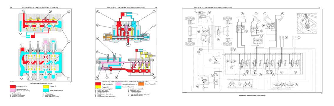
- Color page, page 451
- Color page, page 510
- Foldout diagram, page 490
This is a service manual
Here's how it compares to the other manual types.
Service manual
Factory repair procedures and technical information such as specifications, troubleshooting, and wiring and hydraulic diagrams, for the models and systems the manual covers. See What's inside for its topics.
Operator's manual
Safe operation, controls, maintenance schedules, lubrication points, inspections, and basic checks. Repair procedures are in the service manual.
Parts manual
Illustrated diagrams with factory part numbers for identifying components and ordering parts. Repair procedures are in the service manual.
Engine service manuals are sometimes sold separately, since certain machine models were offered with more than one engine option.
What it's used for
Factory manual for in-house farm and construction shop use. Straightforward, complete, and easy to follow. It contains the OEM information dealership service departments and parts counters use to diagnose problems, identify components, and perform maintenance or repairs correctly.
Service shops and owner/operators who repair their own equipment
Identifying correct parts and seeing how assemblies come apart and go back together
Keeping equipment running with less downtime
Factory manual, 945 pages
Quantity one is the manual described above.
Fast free USA shipping
Ships in 1 business day.
60-day returns
Free if the mistake is ours. A manual ordered in error must come back unopened in its shrink-wrap; you pay return shipping and a 20% restocking fee applies. Return policy
Binder not included
Manuals over about 300 pages may need a standard 3-ring binder, which you can buy locally to keep the pages organized for shop use.
Questions about model, serial number, engine coverage or contents? Contact us before purchasing and we'll help confirm it's the right manual. Please verify the manual type, machine model, serial number range and engine coverage before purchasing: manuals ordered in error carry a 20% restocking fee (return policy).