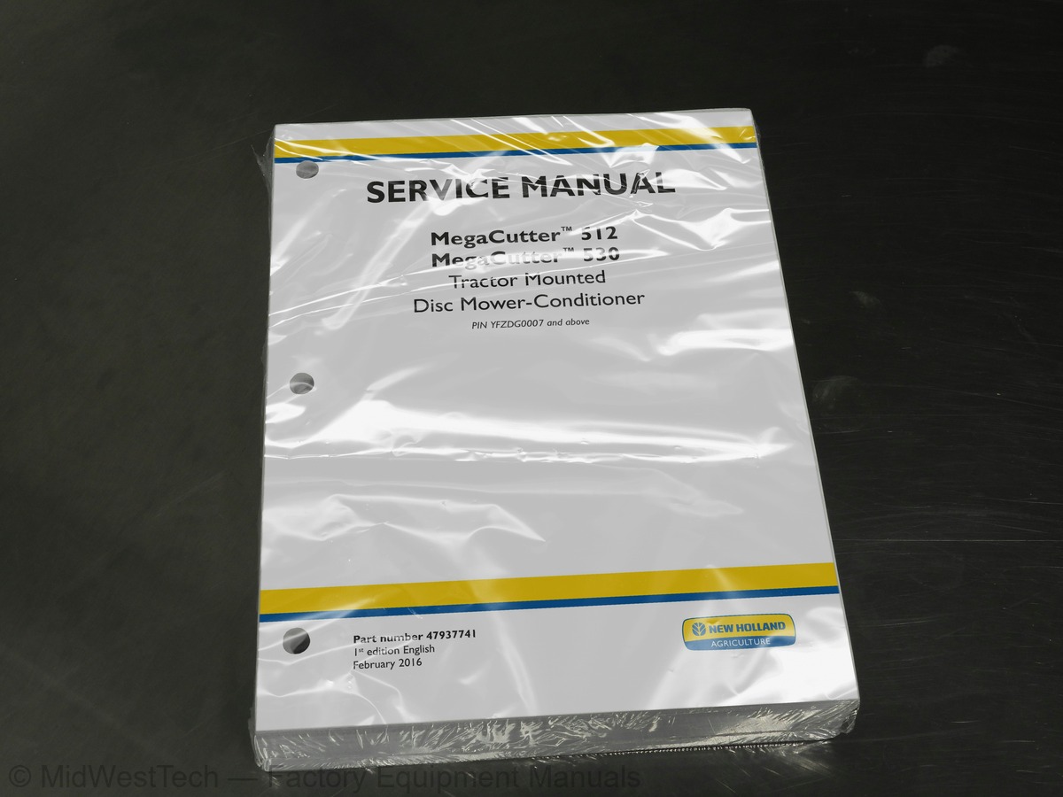
New Holland MegaCutter 512, 530 Tractor Mounted Disc Mower Conditioner Service Manual
527 pages · Publication 47937741
Added to your cart. View cart
- Models
- MegaCutter 512, 530 Tractor Mounted Disc
- Serial coverage
- PIN YFZDG0007 and above
- Manual type
- Service Manual
- Pages
- 527
- Publication
- 47937741
- Condition
- Brand new
What's inside
From the manual's own table of contents: 173 topics. See sample pages (PDF, 598 KB)
- Main gearbox and drive
- Power Take-Off (PTO)
- Power Take-Off (PTO) drive shaft
- Secondary Power Take-Off (PTO)
- Clutches
- Hydraulic systems
- Main lift system
- Reservoir, cooler, and filters
- Main control valve
- Header or attachment height system
- Frame positioning swinging
- Frames and ballasting
- Drawbar and hitch assembly
- Electrical systems
- Electrical system
- Hydraulic system control
- Rear Power Take-Off (PTO) control system
- Harnesses and connectors
- External lighting
- Frame positioning system
- Attachments/Headers
- Attachment/Header cutting mechanism
- Attachment/Header frame
- Foreword - Important notice regarding equipment servicing
Show all 173 topics
- Safety rules
- Safety rules – Personal safety
- Safety rules - Ecology and the environment
- Torque - Nominal tightening torques for normal assembly
- Basic instructions - Shop and assembly
- General specification – MegaCutter™512 (*)
- General specification – MegaCutter™530 (*)
- Capacities
- Product identification – MegaCutter™512 (*)
- Product identification – Machine orientation – MegaCutter™512 (*)
- Product identification – MegaCutter™530 (*)
- Product identification – Machine orientation – MegaCutter™530 (*)
- Service instruction – Change gearbox shaft rotation
- Remove
- Disassemble
- Assemble
- Install
- Change fluid – Rear cutting units (*)
- Check fluid level – Rear cutting units (*)
- Change fluid – Front cutting unit (*)
- Check fluid level – Front cutting unit (*)
- Adjust length
- Troubleshooting
- Overview
- Component localization
- General information – Spool valves
- General information – Check valves
- Hydraulic schema
- Overview – Suspension system
- Dynamic description – Suspension system
- Remove – Suspension cylinder
- Install – Suspension cylinder
- Technical Data
- Replace
- Inspect
- Service instruction – Discharge pressure from the brake system accumulator
- Test – Brake system accumulator pressure
- Torque
- Identification
- Service instruction – Installing a spool valve into the port on the valve manifold
- Remove – Flow divider
- Install – Flow divider
- Remove – V3 - Lower front valve (Y-7007)
- Install – V3 - Lower front valve (Y-7007)
- Remove – V4 - Lift unit left valve (Y-7000)
- Install – V4 - Lift unit left valve (Y-7000)
- Remove – V5 - Lift unit right valve (Y-7001)
- Install – V5 - Lift unit right valve (Y-7001)
- Remove – V6 - Lower suspension valve (Y-7005)
- Install – V6 - Lower suspension valve (Y-7005)
- Remove – V7 - Lift suspension valve (Y-7004)
- Dynamic description – Rear cutting unit position cylinders
- Dynamic description – Front cutting unit position cylinder
- Remove – Cutting unit position cylinder
- Install – Cutting unit position cylinder
- Overview – Brake system
- Dynamic description – Brake system
- Remove – Brake system
- Install – Brake system
- Identification – MegaCutter Control Module (MCM) A-7000
- General information – Control systems
- Overview – ISOBUS – Automatic Headland Control (AHC) settings
- Overview – Joystick control – Automatic Headland Control (AHC)
- Install – Control system
- Control identification – ISOBUS – Display monitor
- Control identification – ISOBUS – Controls overview
- Calibrate – ISOBUS – Automatic Headland Control (AHC)
- Control – ISOBUS – Manual mode
- Control identification – Joystick control – General information
- Control identification – Joystick control – Controls overview
- Calibrate – Joystick control – Automatic Headland Control (AHC)
- Control – Joystick control – Manual mode
- Service instruction – Dealer menu (ISOBUS)
- Service instruction – Dealer solenoid diagnostic menu (ISOBUS)
- Service instruction – Dealer sensor diagnostic menu (ISOBUS)
- Service instruction – Dealer menu (non-ISOBUS joystick)
- Service instruction – Dealer solenoid diagnostic menu (non-ISOBUS joystick)
- Service instruction – Dealer sensor diagnostic menu (non-ISOBUS joystick)
- Dynamic description – Rear cutting unit position
- Dynamic description – Front cutting unit position
- Remove – Y-7000 - Lift unit left valve (V4)
- Install – Y-7000 - Lift unit left valve (V4)
- Remove – Y-7001 - Lift unit right valve (V5)
- Install – Y-7001 - Lift unit right valve (V5)
- Remove – Y-7002 - Lower units valve (V9)
- Install – Y-7002 - Lower units valve (V9)
- Remove – Y-7004 - Lift suspension valve (V7)
- Install – Y-7004 - Lift suspension valve (V7)
- Remove – Y-7005 - Lower suspension valve (V6)
- Install – Y-7005 - Lower suspension valve (V6)
- Remove – Y-7006 - Main control (bypass oil) valve (V8)
- Install – Y-7006 - Main control (bypass oil) valve (V8)
- Remove – Y-7007 - Lower front valve (V3)
- Install – Y-7007 - Lower front valve (V3)
- Remove – Y-7008 - Lift front valve (V11)
- Install – Y-7008 - Lift front valve (V11)
- General specification
- Electrical schematic sheet 01 – Front and rear machine control
- Electrical schematic sheet 02 – ISOBUS joystick
- Electrical schematic sheet 03 – Lighting
- Electrical schematic sheet 04 – Non-ISOBUS joystick
- Component diagram 00 – Connectors X-7000 to X-7009
- Component diagram 01 – Connectors X-7010 to X-7019
- Component diagram 02 – Connectors X-7020 to X-7029
- Component diagram 03 – Connectors X-7030 to X-7039
- Component diagram 04 – Connectors X-7040 to X-7049
- Component diagram 05 – Connectors X-7050 to X-7059
- Component diagram 06 – Connectors X-7060 to X-7069
- ECU description
- Sensor description
- Diode description
- Solenoid description
- Service instruction – Wire pins on circuit board
- Testing – B-7001 - Transport position sensor (S3) (both rear cutting units will not lower)
- Testing – B-7003 - Left-hand cutting unit position sensor (S1) (left-hand cutting unit will not lower)
- Overview – Rear cutting units (*)
- Overview – Front cutting unit (*)
- Replace (*)
- Remove – Bevel gearbox – Rear cutting units (*)
- Disassemble – Bevel gearbox
- Assemble – Bevel gearbox
- Install – Bevel gearbox – Rear cutting units (*)
- Remove – Bevel gearbox – Front cutting unit (*)
- Install – Bevel gearbox – Front cutting unit (*)
- Remove – Rear cutting units (*)
- Install – Rear cutting units (*)
- Remove – Front cutting unit (*)
- Install – Front cutting unit (*)
- Inspect – Rear cutting units (*)
- Remove – Curtain assembly
- Install – Curtain assembly
- Inspect – Curtain assembly
- Remove – Swathgate
- Install – Swathgate
- Remove – Flotation springs
- Install – Flotation springs
- Troubleshooting – Rear cutting units
- Dynamic description
- Overview – Front cutting units (*)
- Adjust
- Replace – V-belts – Rear cutting units (*)
- Replace – V-belts – Front cutting unit (*)
- Remove – Belt tensioner – Rear cutting units
- Install – Belt tensioner – Rear cutting units
- Remove – Belt tensioner – Front cutting unit
- Install – Belt tensioner – Front cutting unit
- Replace – Flails
- Remove – Rotor
- Install – Rotor
Inside this manual
Real pages from this service manual (527 pages). Open the sample pages (PDF, 597 KB)

- Troubleshooting, page 88: Power Take-Off (PTO) - Clutches
- Specifications, page 120: Hydraulic systems - Reservoir, cooler, and filters
- Diagram, page 344: Electrical systems - Harnesses and connectors
- Color page, page 234: Electrical systems - Electrical system
- Color page, page 438: Attachments/Headers - Attachment/Header cutting mechanism
- Foldout diagram, page 318: Electrical systems - Harnesses and connectors
This is a service manual
Here's how it compares to the other manual types.
Service manual
Factory repair procedures and technical information such as specifications, troubleshooting, and wiring and hydraulic diagrams, for the models and systems the manual covers. See What's inside for its topics.
Operator's manual
Safe operation, controls, maintenance schedules, lubrication points, inspections, and basic checks. Repair procedures are in the service manual.
Parts manual
Illustrated diagrams with factory part numbers for identifying components and ordering parts. Repair procedures are in the service manual.
Engine service manuals are sometimes sold separately, since certain machine models were offered with more than one engine option.
What it's used for
Factory manual for in-house farm and construction shop use. Straightforward, complete, and easy to follow. It contains the OEM information dealership service departments and parts counters use to diagnose problems, identify components, and perform maintenance or repairs correctly.
Service shops and owner/operators who repair their own equipment
Identifying correct parts and seeing how assemblies come apart and go back together
Keeping equipment running with less downtime
Factory manual, 527 pages
Quantity one is the manual described above.
Fast free USA shipping
Ships in 1 business day.
60-day returns
Free if the mistake is ours. A manual ordered in error must come back unopened in its shrink-wrap; you pay return shipping and a 20% restocking fee applies. Return policy
Binder not included
Manuals over about 300 pages may need a standard 3-ring binder, which you can buy locally to keep the pages organized for shop use.
Other editions and similar models
Questions about model, serial number, engine coverage or contents? Contact us before purchasing and we'll help confirm it's the right manual. Please verify the manual type, machine model, serial number range and engine coverage before purchasing: manuals ordered in error carry a 20% restocking fee (return policy).