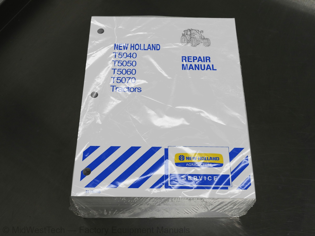
New Holland T5040, T5050, T5060, T5070 Tractor Service Manual
1,755 pages · Publication 84195945
Added to your cart. View cart
What's inside
From the manual's own table of contents: 80 sections, 700 entries. See sample pages (PDF, 678 KB)
Show all 80 sections
Overhaul18 topics
- Engine
- Removal
- Installation
- Crankshaft Front Seal
- Crankshaft Rear Seal
- Valve Tappet and Rocker Arm Clearance
- Adjustment
- Assembly
- Engine Injector
- Bosch Injection Pump
- Injector Pump
- Disassembly
- Fuel Circuit Air Bleeding
- Coolant Pump
- Thermostat Valve
- Radiator
- Coolant Pump and Generator Drive Belts
- Adjusting Tension
Sectional Views6 topics
- Longitudinal Section of 12 ″ LUK Clutch
- Electrohydraulic Power Take-off
- Longitudinal Section of 12 ″ /12 ″ LUK Clutch
- Mechanical Power take--off
- Longitudinal Section Through Flexible Coupling
- Power Shuttle Unit
Checks, Measurements and Repairs5 topics
- Main Transmission Clutch Release
- Clutch
- Test Bench Overhaul and Adjustment
- Coplanarity Adjustment of Dual Clutch Release Levers
- Single Disk Clutch
Description and Operation24 topics
- Clutch-reverser Casing
- Reverser-clutch Casing and Creeper Unit
- Output Shaft Synchronizer Support
- Speed Transmission
- Main Hydraulic Circuit
- Power Shuttle Transmission Lubrication Circuit
- Power Shuttle Transmission - Clutch A At Rest / Engaged
- Diagrams
- Range and Gear Position Sensor Adjustment
- Gear Lever Status Switch
- Range Lever Status Switches
- Adjustment Check
- Clutch Casing With Power Shuttle
- Driving Shaft
- Main Shaft Removal
- Clutch A
- Replacing the Seal on the Clutch Casing Internal Hub
- Clutch B
- Disassembly - Assembly
- Calibration
- Fault Codes
- HH Menu Access
- Clutch Calibration H1 Menu Transmission
- Transmission Fault Codes
Bolt Torques95 topics
- Dual Command (2 Speed Power Shit) Unit
- (2 Speed Power Shift) Functions
- (2 Speed Power Shift) Units
- Driven Shaft
- Fault Code Descriptions
- Electro-hydraulically Engaged Drive Gear
- Services Control Valve
- Services Control Valve (For Tractors Without Power Shuttle)
- Drive Gear Assembly
- Drive Gear Housing Removed
- Self-locking Differential Operation
- Front Differential Lock
- Rules for Correctly Installing the Axle Support to the Engine
- Front Axle
- Front Axle Differential
- Overhaul
- Front Axle Differential with LIM--SLIP Unit
- Front Axle Differential Lock Clutch Assembly
- Front Epicyclic Final Drive without Brake
- Front Epicyclic Final Drive with Brake
- Wheel Hub Seal with Brake
- Replacement
- Stub Axle Adjustments
- Pinion and Crown Wheel Adjustments
- Adjusting the Bevel Pinion Shaft Bearing Preload with Shims
- Clearance Between the Sides of the Bevel Drive Teeth
- Hydraulically Controlled Rear Differential Lock
- Rear Gearbox - Transmission Casing
- Gearbox Transmission Casing
- Gearbox Driving Shaft End Float Adjustment
- Adjusting the Position of Differential Lock Engagement Sleeve
- Determining the Bevel Pinion Positioning Adjustment Ring
- Adjusting the Bevel Gear Pair
- Tapered Roller Bearings Adjustment for Pinion Shaft
- Clearance Between the Bevel Drive Teeth
- Bevel Drive Adjustments
- Adjusting the Preloading on the Bevel Drive Bearings
- Adjustment of the Clearance Between the Sun and Planet Pinion Teeth
- Differential Lock Control Pedal Stroke
- Final Drive Casing
- Epicyclic Final Drive
- Drive Wheel Shaft
- Mechanical PTO
- PTO Controlled Directly from the Engine Clutch
- PTO Synchronized With Gears
- Selecting the Speed With the Lever
- Cooling System
- Power Take-off Housing
- Mechanical Power Take--off Shafts
- Electrohydraulic PTO
- (Directly by Flywheel)
- PTO Synchronized to Gearbox
- Rod (4) in the PTO Synchronized with Gearbox Position
- 540 - 1000 Rpm Electrohydraulic PTO ”NASO” Version
- Rpm PTO with Electrohydraulic Engagement
- Hydraulic System
- Additional PTO Controls for Cab-version Tractors with Power Shuttle Transmissions
- External Controls on Mudguards (If Installed)
- Modulating Function Selection (If Installed)
- Rear PTO Fault Codes
- Power Take-off Clutch Brake
- Electro-Hydraulic Power Take-off Housing
- Service Brakes
- Service Brake on Front Axle
- Parking Brake
- Pilot Valve Operation
- Brakes at Rest
- Braking Applied on Just One Pedal
- Braking Applied on Both Brake Pedals
- Hand Brake Control
- Travel Adjustment
- Parking Brake Casing
- Brakes Hydraulic System
- Air Bleed
- Tractor Equipped with Hydraulic Trailer Braking Valve
- Tractor Equipped with Braking on the Front Axle
- Tractor Equipped with Pneumatic Trailer Braking Valve
- Service Brake Pump
- Adjusting the Height of the Service Brakes Pedals
- Right or Left Brake
- Brakes Disengaged
- Dual Line Braking System
- Single Line Braking System
- Brakes Engaged
- Description Air Brake Circuit Components
- Compressor
- Antifreeze Pump
- Pressure Regulating Valve
- Dual Line Control Valve
- Pressure Switch
- Tank
- Single Line Control Valve
- Black Connection
- Red / Yellow Connection
- ADIC Dashboard
Tests and Adjustments62 topics
- Pressure Testing
- Tractor Preparation
- Pre-test Procedure
- Test
- Hand Brake Control Cable Adjustment
- Leak Test
- Brake Pedal Test Procedure
- Pressure Regulator ON/OFF Test Procedure
- Hydraulic Lift Circuit
- Arm Lift Phase
- Neutral Phase
- Arm Lower Phase
- Lift Oil Pump
- Disassembly - Assembly With Pump Removed to Replace the Seal Kit
- Fast Raise/Lower Control
- Linkage Adjustments
- Position Control Rod Adjustments
- Draft Control Rod Adjustments
- Fast Raise/Lower Device Adjustments
- Adjustment of the Upper Stroke Limit of the Fast Raise/Lower Device
- Rear Lift External Controls
- Rear Lift
- Rear Hydraulic Lift
- Lift Adjustments
- Adjusting Position Control
- Lift Arms Maximum Raise Position Adjustment
- Adjusting Draft Control
- Lift Control Valve
- Lift Pressure Relief Valve
- Operation
- Lifting
- Neutral
- Lowering
- Float
- Operating Stages of Auxiliary Control Valve for Operation of a Single-acting Cylinder
- Operating Stages of Auxiliary Control Valve for Operation of a Double-acting Cylinder
- Double-acting Cylinder with Automatic Detent Release and Float
- Float Operation
- Auxiliary Control Valves
- Valve Leakage Test
- Adjustment of the Automatic Detent Release Pressure
- Float Mode
- Flow Control Valve Adjustment
- Flow Control Valve
- Load Check Valve
- Lockout Valve
- Control Valve Pin
- Pin Centering and Automatic Release Mechanism
- Lifting Oil Flow (Cylinder Extension)
- Lowering Oil Flow (Cylinder Retraction)
- Oil Flow In Neutral
- Float Mode Oil Flow
- Automatic Release Pressure Regulating Valve Operation
- Operation of Two or More Auxiliary Control Valves Simultaneously
- Disassembly - With the Unit Removed
- Connecting Plate
- Quick Coupler Maintenance
- Introduction
- Maintenance Operations
- Trailer Brakes Off
- Start of Braking
- Braking
Troubleshooting and Testing8 topics
- Trailer Brake Valve - Italia Version
- Incorporated in the Trailer Brake Control Valve
- Testing the Hydraulic System for Leakage
- Parking Brake is Applied
- Troubleshooting
- Check Calibration on Switches
- Supplementary Cylinder
- Removal - Installation
Electronically Controlled Hydraulic Lift20 topics
- EDC Control Mouse
- Position Control Lever
- Draft Control Ring
- Lift, Lower, Fast Ground Entry Button (Fast Raise/Lower)
- Position Lever Adjustment Knob
- Setting Potentiometers Panel
- Sensitivity Adjustment Potentiometer
- Lowering Speed Adjustment Potentiometer
- Height Limit Potentiometer
- Slip Limit Setting Potentiometer
- Indicator Light Panel
- Slip Lamp
- Lift Disabled / Failure Warning Light
- Arms Lifting and Lowering Warning Lights
- Position Mode
- Draft Mode
- Lift Restoration
- Smooth Ride Device
- Lifting Phase
- Lowering Phase
Fault Finding73 topics
- Lift Fault Codes
- Lift Arms Position Display
- Transmission Fault Codes Listing
- Calibrations
- Calibration H1 Menu Lift
- Pre--test Procedure
- Arm Position Control Potentiometer Calibration
- Solenoid Valve Calibration
- Transmission, Lift and Services Electronic Control Unit
- EDC Control Mouse, Indicator Light Panel and Ceiling Light
- Lift Arm Potentiometer
- Draft Sensor
- Electronic Draft Control
- Hydraulic Control Valve
- Ventral Control Valve Joystick
- Joystick Operation
- 2nd Control Valve Regenerating Function Disabling Bush
- Ventral Control Valve
- Operation in the Neutral Phase
- Operation 1st Control Valve in Lowering Phase
- Operation 1st Control Valve in Floating Phase
- Operation 1st Control Valve in Lifting Phase
- Operation 2nd Control Valve in Lifting Phase
- Operation 2nd Control Valve in Regenerating Phase
- Operation 2nd Control Valve in Lowering Phase
- Balancing Valve Components (2WD)
- Neutral Position
- Steering To Right
- Steering To the Left
- Manual Turning To the Right
- Manual Turning to the Left
- Hydrostatic Steering Control Valve
- Hydrostatic Steering Control Valve With Control Valve Removed
- Bench Test
- Checking Rotating Valve Wear
- Checking Return to Neutral Position
- Seal Check
- Pressure Relief Valve Calibration
- Control Valve Installed on Tractor
- Power Steering Oil Pump
- Front Axle Steering Cylinder (4WD)
- Front Axle Steering Cylinder (2WD)
- 2WD Front Wheel Track Diagram
- Front Axle Hub
- Stub Axle
- Checking 2WD Front Wheel Camber and Toe--in
- Checking 4WD Front Wheel Alignment
- Main Components of the Air Conditioning System
- Condenser
- Receiver/Dryer
- Thermostatic Expansion Valve
- Thermostatic Switch - DEFROST
- Evaporator
- Cab Heating and Ventilation Controls
- Ventilation
- Electric Fan
- Air Filter
- Heating
- Temperature Control Knob (1)
- Ignition Switch
- Cab Air Conditioning Controls
- Air Conditioning and Temperature Control Knobs
- Heater Control Knob
- 3-speed Electric Fan Control Knob
- Instructions for Use
- Start Up
- Switching Off
- Meaning
- Checking for Refrigerant Leaks Using an Electronic Leak Detector
- Refrigerant Gas Leak Test
- Maintenance
- Maintenance of the Air Conditioning System
- Visual Inspection of Components
Checks and Adjustments16 topics
- Functional Tests
- Checking the Temperature of the Air Coming Out of the Vents Inside the Cab
- Variations in Working Temperatures of the Cab Air Conditioning System
- Checking for and Eliminating any Gas Leaks
- Compressor Drive Belt
- Fitting the Compressor Drive Belt
- Tension Adjustment
- Periodic Checking of Drive Belt
- Air Conditioning Compressor
- Compressor Oil
- Type and Quantity
- Heating Pipes
- Air Conditioning Pipes
- Air Conditioner Condenser
- Cab Heating Unit
- Air Conditioner Evaporator
Control Panel6 topics
- Standard Dashboard
- Analog/Digital Instrumentation Panel
- Instruments
- Rev Counter
- Engine Coolant Temperature Indicator
- Fuel Level Indicator
Liquid Crystal Displays8 topics
- Clock
- Central Display
- Ground Speed Display
- Information Monitor
- Setting and Resetting the Hours Worked
- Resetting Hours Worked
- Setting Hours Worked on a New Dashboard
- Brightness Control
Access to the “Setup Menu” via Keypad64 topics
- Manual Calibration
- Automatic Forward Speed Calibration
- 12/24 - Hour System Clock Setting
- Speed Unit of Measurement Setting
- Beep Setting
- Implement Width Setting
- Slip Percentage Setting
- Heavy/Light Maintenance Setting
- Access to the “Warnings Not Displayed” Menu
- Warnings of a Critical Nature
- Warnings of a Non-critical Nature
- Calling Up Functions from Keypad
- Area Worked
- Area Per Hour
- Odometer
- Maintenance Periods
- Hours Worked, Air Brake Pressure Brake and Battery Charge
- Wheel Slip and Power Take-off Speed
- Rear Implement Position
- Access to the “Setup Menu” with the CAL Button
- Calling Up Functions with the CAL Button
- Dashboard Controls
- Lights/Horn Switch
- Direction Indicators
- Tail/Side Lights, Full Beam, Dipped Beam Circuit and Front Headlight Flash
- Horn
- Flashing Hazard Warning Lights Switch
- Swivel Work Lights Switch
- Differential Lock Switch (Version Without Cab)
- Differential Lock switch (Version With Cab)
- Four-wheel Drive Switch (Version With Cab)
- Four-wheel Drive Switch (Version Without Cab)
- Full/Dipped Beam Headlight Switch for Front Loader (Version With Cab)
- Modulated Power Take-off Switch (Version With Cab)
- Advanced Keypad
- Instrument Calibration Switch (Version Without Advanced Keypad)
- Front Windshield Washer/Wiper Control Lever
- Key-start Ignition Switch
- Power Shuttle Reverser
- Controls on Right-hand Mudguard
- Controls for Standard Cab Version
- Controls on Right-hand Mudguard (Version Without Cab)
- Clutch Cut-out”12 Push Buttons
- Ventral Control Valve Joystick for Loader
- Controls on Right-hand Mudguard (Version with Electronic Lift)
- Electronic Lift Control Panels Control Mouse
- Electronic Lift Control Panels Setting Potentiometers
- Electronic Lift Control Panels Warning Light Panel
- In-cab Controls
- Cab Interior Light
- Temperature Control Knob
- HVAC Controls
- Air Conditioning and Temperature Control Knob
- Heater Control
- Controls on Right-hand Cab Upright
- Controls Lighting
- Rear Work Lights Control Switch
- Windshield Wiper/Washer Switch
- Electrohydraulic PTO Switch (Version With Cab)
- Rotating Beacon Light ON/OFF Switch
- Front Work Lights Control Switch
- External Controls
- External PTO Controls
- Electronic Lift Up and Down External Buttons
Maintenance6 topics
- Lamp/Bulb Replacement
- Full/Dipped Beam Headlight Bulbs
- Swivel Work Light Bulbs
- Front Sidelight and Direction Indicator Lamp Bulb Replacement
- Work Lights Lamp Bulb Replacement
- Replacing the Rear Side, Stop and Indicator Light Bulbs
Starter and Recharging Circuits3 topics
- Manual Transmission
- Fault Diagnosis
- Power Shuttle Transmissions
System Tests10 topics
- Starting System Test on Tractor
- Current Absorbed on the Starter Motor Circuit
- Starting System Circuit Resistance (Voltage Drop)
- Battery Positive Cable
- Starter Motor Ground Connections
- Battery Ground Lead
- Starter Motor
- Removal--Installation
- Description of the Alternator
- Alternator Operation
System Testing and Troubleshooting6 topics
- Precautions During the Operation
- Preliminary Checks
- Battery
- Drive Belt
- Alternator
- Removal -- Installation
Testing and Charging Procedures13 topics
- Overview
- Batteries Type A
- Batteries Type B
- Testing
- Test Instructions
- Visual Check
- Specific Gravity (Charge Status Test)
- Open Circuit Voltage (Charge Status Test)
- High Discharge Test
- Charge Instructions
- Permissible Charge Test
- Charging
- B-type Batteries
Maxi Fuses9 topics
- Maxi Fuse Box
- Version 1 -- Model With Cab
- Version with Power Shuttle and Electronic Lift
- Version 2 - Standard Version
- Version Without Cab
- Version 3 - Power Shuttle ISO Version
- Version 4 - Standard ISO Version
- Version 5 - Power Shuttle North America Version
- Version 6 - North America Standard Version
Fuse and Relay Layout9 topics
- Fuse and Relay Box
- Version 1 - Model With Cab, Version With Power Shuttle and Electronic Lift
- Fuses
- Relays
- Version 2 - Model With Cab, Standard Version
- Version 3 - Version Without Cab, Version With Power Shuttle - ISO
- Version 4 - Model Without Cab, Standard Version - ISO
- Version 5 -- Version Without Cab and Version With Power Shuttle - North America
- Version 6 - Model Without Cab, Standard Version - North America
Sockets5 topics
- Seven-pole Power Socket
- A Two--pole Power Socket (ISO Version)
- A Power Socket (North America Version)
- AH One--pole Power Socket
- ISO 11786 Implement Socket With 7 Pins
Miscellaneous Modules and Relays3 topics
- Grid Heater Relay
- Grid Heater Control Module
- Electronic Flasher Module
Ground Location Points1 topic
- Ground Points Layout Diagram
Version 1 - Version With Power Shuttle and Electronic Lift - (Cab Version)20 topics
- Circuit Index
- Electrical Circuits Components Version 1
- Battery Cut-out and Hand Brake Circuit - Diagram 1
- Diagnostics Connection and CAN Line Circuit - Diagram 2
- Radio and Auxiliary Functions Circuit - Diagram 3
- Brakes and Differential Lock Circuit - Diagram 4
- Engine, Sensors and Transmitters Circuit - Diagram 5
- Front Loader and 80 Liter (21.1337 Gallon) Combined Valve Circuit - Diagram 6
- Cab Ventilation and Air-conditioning Circuit - Diagram 7
- Instrument Circuit - Diagram 8
- Direction Indicator and Hazard Lights Circuit - Diagram 9
- External Lights Circuit - Diagram 10
- Power Supplies Circuit - Diagram 11
- Rear Power Take-off Circuit - Diagram 12
- Grid Heater and Engine Starter Circuit - Diagram 13
- Power Socket and Trailer Brake Circuit - Diagram 14
- Windshield and Rear Window Washer/Wiper Circuit - Diagram 15
- Work Lights Circuit - Diagram 16
- Power Shuttle Circuit - Diagram 17
- Electronic Lift Circuit (EDC) - Diagram 18
Version 2 - Standard Version - (Cab Version)2 topics
- Electrical Circuits Components Version 2
- Grid Heater and Engine Starter Circuit -- Diagram 13
Version 3 - Version With Power Shuttle ISO - (Deck Version)13 topics
- Electrical Circuits Components Version 3
- Diagnostics Connection and CAN Line Circuit - Diagram 1
- Brakes and Differential Lock Circuit - Diagram 2
- Engine, Sensors and Transmitters Circuit - Diagram 3
- Battery Cut-Out, Hand Brake and Instrument Circuit - Diagram 4
- Direction Indicator and Hazard Lights Circuit - Diagram 5
- External Lights Circuit - Diagram 6
- Power Supplies Circuit - Diagram 7
- Grid Heater and Engine Starter Circuit - Diagram 8
- Power Socket and Trailer Brake Circuit - Diagram 9
- Rear Power Take-Off Circuit - Diagram 10
- Work Lights and Auxiliary Functions Circuit - Diagram 11
- Power Shuttle Circuit - Diagram 12
Version 4 - Standard ISO Version - (Deck Version)1 topic
- Electrical Circuits Components Version 4
Version 5 - Version With Power Shuttle North America - (Deck Version)1 topic
- Electrical Circuits Components Version 5
Version 6 - Standard Version For Shuttle North America - (Deck Version)5 topics
- Electrical Circuits Components Version 6
- (ECU) Power Shuttle 12 x 12 Version
- (TCM) Power Shuttle 24 x 24 Version
- Panel (ADIC)
- Component List - By Device
Harnesses10 topics
- Version 1 - Version With Power Shuttle and Electronic Lift - (Cab Version)
- Index to Wiring Harnesses
- Wiring Diagram Title Index
- Wiring Diagram 17 - 18
- Version 2 - Standard Version - (Cab Version)
- Version 3 - Version With Power Shuttle ISO - (Deck Version)
- Wiring Diagram 12
- Version 4 - Standard ISO Version - (Deck Version)
- Version 5 - Version With Power Shuttle North America - (Deck Version)
- Version 6 - Standard Version for North America - (Deck Version)
Description of Components38 topics
- Components
- Gearbox oil pressure switch (Sen--311)
- Coolant temperature sensor (Sen--306)
- Sediment filter (Sen--305)
- Engine rpm sensor (Sen--315)
- Components 5 through 8
- Right brake switch (SW--318)
- Air filter clogged switch (SW--303)
- Brake fluid level switch (SW--312)
- Mechanical battery cut--out switch (SW--97)
- Components 9 through 11
- Temperature gauge sensor (SEN--309)
- Engine oil pressure switch (SEN--313)
- 10a Gearbox oil pressure switch (Sen--311)
- 11 80 liter supplement solenoid valve (SOL--330)
- Components 12 through 18
- Handbrake switch (SW--73)
- CAN Terminator
- Clutch pedal potentiometer (RES--156)
- Clutch pedal switch (SW--35)
- Air brake pressure switch (SEN--340)
- Components 19 through 22
- Lift--O--Matic switch (SW--64)
- Gear lever (SW--13)
- Gear lever status switches
- Components 23 through 26
- Shuttle lever switch (SW--79)
- 24 4WD disengagement solenoid valve (SOL--214)
- Fuel level sensor (SEN--212)
- Theoretical wheel speed sensor (SEN--217)
- Components 27 through 30
- Operator present switch (SW--59)
- Gearbox control valve
- Components 31 through 34
- Arms position sensor (SEN--224)
- Differential lock warning light switch (SW--216)
- PTO speed sensor (SEN--218)
- Left sensor (SEN--225)
Introduction1 topic
- Fault Codes and Fault Finding
Wiring Harness Repairs2 topics
- Temporary Wiring Harness Repair
- Harness Wire Replacement
Digital Multimeter - Basic Operation1 topic
- Digital Multimeter
Circuit Components - Basic Description20 topics
- Circuit Protection Devices
- Fuses, Fusible Links
- Fuse Links
- Circuit Control Devices
- Switches
- Flashers
- Diodes
- Resistance Devices
- Potentiometers
- Electromagnetic Devices
- Solenoid Valves
- Proportional Solenoid Valves (PWM)
- Sensors
- Temperature Sensors
- Pressure Sender
- Speed Sensor
- Fluid Level Sender
- Electronic Control Units
- Fault Code Display for the Panel (ADIC) and Transmission (XCM)
- H--Menu Diagnostic Mode
Fault Code Lists8 topics
- Electronic Lift Error Codes
- Transmission Fault Code Listing
- Rear PTO Fault Code Listing
- Four Wheel Drive Error Code Listing
- Differential Lock Error Code Listing
- Analog-digital Instrument Cluster (ADIC) Error Code Listing
- Calibration U-code Listing
- List of Electronic Lift Error Codes
Fault Code Descriptions28 topics
- Calibration U-codes
- Error Code U19 -- Transmission Oil Temperature is Below 10 Degrees Centigrade
- Error Code U20 -- Incorrect Sequence, Cycle Shuttle Lever and Pedal Switch
- Error Code U21 -- Engine Speed is Too Low, Increase Engine Speed
- Error Code U22 -- Engine Speed is Too High, Reduce Engine Speed
- Error Code U23 -- Shuttle Lever is in Neutral, Shift Lever to Forward
- Error Code U24 -- Incorrect Range Selected
- Error Code U25 -- Main Gear Lever is in Neutral
- Error Code U26 -- Clutch Pedal is Not Up, Release Clutch Pedal
- Error Code U31 -- Wheel Speed Detected
- Error Code U33 -- Hand Brake is not Engaged
- Error Code U34 -- Operator Present Seat Switch Off
- Error Code U36 -- Calibration Value Too High
- Error Code U37 -- Calibration Value Too Low
- Error Code U38 -- Range Lever is in Neutral
- 1001 - 2000 Electronic Draft Control (EDC)
- Error Code 1002 -- Radar Signal Not Present
- Error Code 1003 -- No Signal From Speed Sensor
- Error Code 1004 -- Speed Sensor Signal Too High
- (Short or Open Circuit)
- (Short to + 12 Volt)
- Error Code 1008 -- Raise / Lower Switch Failure
- Error Code 1009 -- Both External Switches Operated at Same Time
- Error Code 1011 -- Height Limit Potentiometer Signal Too High (Short to + 12 Volt)
- Error Code 1013 -- Drop Rate Potentiometer Signal Too High (Short to + 12 Volt)
- Error Code 1014 -- R/H Load Sensing Pin Signal Too Low (Short or Open Circuit)
- Error Code 1015 -- R/H Load Sensing Pin Signal Too High (Short to + 12 Volt)
- Error Code 1016 -- L/H Load Sensing Pin Signal Too Low (Short or Open Circuit)
Inside this manual
Real pages from this service manual (1,755 pages). Open the sample pages (PDF, 678 KB)
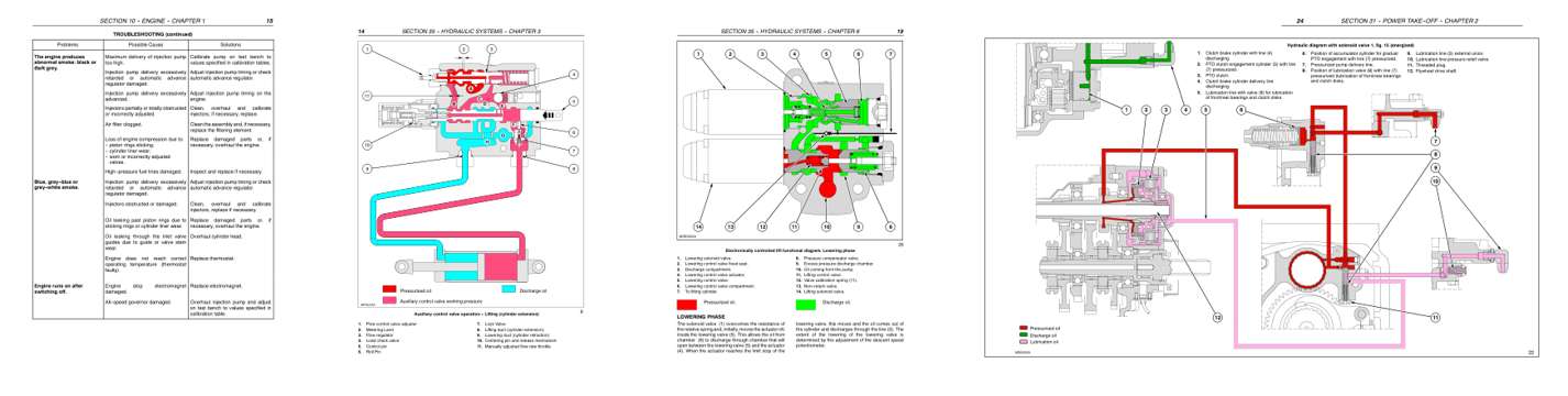
- Troubleshooting, page 100: SECTION 10 -- ENGINE -- CHAPTER 1
- Color page
- Color page
- Foldout diagram (color): SECTION 31 -- POWER TAKE--OFF -- CHAPTER 2
Other manuals for this machine
Save 10% on 2 manuals, 15% on 3 or more. Other manuals for the T5040, T5050, T5060, T5070 are listed below. Editions cover different serial number ranges: check the serial coverage and tick only the ones that match your machine.
Added to your cart. View cart
This is a service manual
Here's how it compares to the other manual types.
Service manual
Factory repair procedures and technical information such as specifications, troubleshooting, and wiring and hydraulic diagrams, for the models and systems the manual covers. See What's inside for its topics.
Operator's manual
Safe operation, controls, maintenance schedules, lubrication points, inspections, and basic checks. Repair procedures are in the service manual.
Parts manual
Illustrated diagrams with factory part numbers for identifying components and ordering parts. Repair procedures are in the service manual.
Engine service manuals are sometimes sold separately, since certain machine models were offered with more than one engine option.
What it's used for
Factory manual for in-house farm and construction shop use. Straightforward, complete, and easy to follow. It contains the OEM information dealership service departments and parts counters use to diagnose problems, identify components, and perform maintenance or repairs correctly.
Service shops and owner/operators who repair their own equipment
Identifying correct parts and seeing how assemblies come apart and go back together
Keeping equipment running with less downtime
Factory manual, 1,755 pages
Quantity one is the manual described above.
Fast free USA shipping
Ships in 1 business day.
60-day returns
Free if the mistake is ours. A manual ordered in error must come back unopened in its shrink-wrap; you pay return shipping and a 20% restocking fee applies. Return policy
Binder not included
Manuals over about 300 pages may need a standard 3-ring binder, which you can buy locally to keep the pages organized for shop use.
Other editions and similar models
Questions about model, serial number, engine coverage or contents? Contact us before purchasing and we'll help confirm it's the right manual. Please verify the manual type, machine model, serial number range and engine coverage before purchasing: manuals ordered in error carry a 20% restocking fee (return policy).