New Holland TM120, TM130, TM140, TM155, TM175, TM190 Tractor Service Manual
3,303 pages · Publication 87611238
Added to your cart. View cart
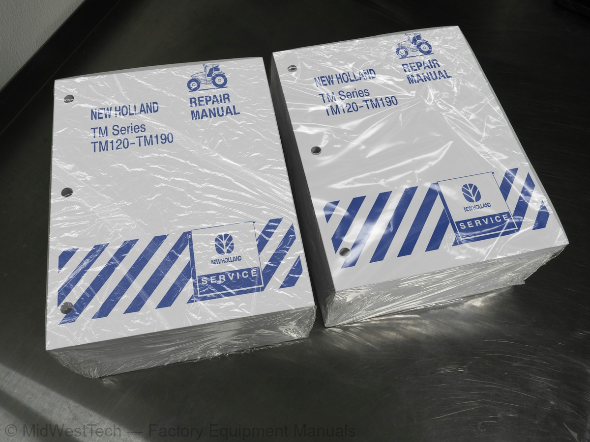
What's inside
From the manual's own table of contents: 371 sections, 700 entries. See sample pages (PDF, 796 KB)
Show all 371 sections
Front Axle and Support2 topics
- Separating Front Axle and Support from Engine
- Installation
Engine and Front Support1 topic
- Separating Engine and Front Support from Transmission
Engine1 topic
- Removal
Introduction2 topics
- With the Engine Still in the Vehicle
- Timing Check
Cylinder Head, Valves, and Related Parts4 topics
- Cylinder Head Removal
- Cylinder Head Disassembly
- Cylinder Head Inspection and Repair
- Cylinder Head Assembly
Engine Front Cover and Timing Gears1 topic
- Timing Gears Check and Removal
Oil Pan1 topic
- Inspection and Repair
Rear Cover Plate1 topic
- Disassembly
Camshaft Bearings2 topics
- Camshaft and Tappet Installation
- Connecting Rod Bush Replacement
Cylinder Block Overhaul4 topics
- Cylinder Bore
- Sleeving -- Boring and Honing
- Piston and Piston Ring Replacement and Installation
- Assembly
Engine Compression Test3 topics
- Test Procedure
- Test Readings
- Test Conclusion
Cooling System -- (CNH 7.5 Liter Engine)6 topics
- Thermostat
- Water Pump
- Drive Belt
- Cooling Capacities
- Coolant Flow
- Cooling Fluid
Vistronic Fan Assembly2 topics
- Clutch Testing
- Fan Blade Removal
Constant Engine Speed Control2 topics
- and 190 Tractors
- High RPM Switch Priority
Bosch VE Type Fuel Injection Pump (Mechanically Governed)2 topics
- Inspection
- Fuel Injection Pump Timing and Installation
Bosch VP Fuel Injection Pump (Electronically Controlled)1 topic
- System Diagram
Fuel Injectors1 topic
- Testing
Turbocharger1 topic
- Cleaning
Air Intake Components1 topic
- Description of Operation
Air Cleaner2 topics
- Disassembly (Mechanically Governed Engines)
- Disassembly (Electronically Governed Engines)
Main Fuel Tank1 topic
- Removal and Installation
Foot Throttle Cable (Mechanically Governed Engines)2 topics
- Replacement
- Adjustment
Description and Operation1 topic
- Operation
Clutch1 topic
- Disassembly and Assembly
Clutch Hydraulic Control4 topics
- Removal-Installation
- Clutch Pedal Adjustment
- Disassembly--Assembly
- Clutch Control Hydraulic Circuit Bleeding
Gear Selection Sequence5 topics
- Selecting a Gear -- No Clutch Pedal
- Selecting a Gear With Clutch Pedal
- Range Shifting
- Shuttling
- Failed Synchronizer Engagement
Semi-Powershift Transmission Oil Flow Illustrations5 topics
- Semi-Powershift Transmission Oil Flow with 1st Gear Forward Engaged
- Semi-Powershift Transmission Oil Flow with 6th Gear Forward Engaged
- Power Flow 1st Gear Medium Range--Forward
- Power Flow 2nd Gear Medium Range--Forward
- Power Flow 2nd Gear Medium Range--Reverse
Limp Home Feature2 topics
- Description
- Instructions
Transmission Clutches, A, B, C, D and E1 topic
- Pressure Test
Clutch and Synchronizer Calibration2 topics
- Calibration Procedure
- Tractor Preparation
Transmission Overhaul1 topic
- Adjustments -- Internal Components
Full Powershift Transmission Power Flows4 topics
- 1st Gear Selected
- 10th Gear Selected
- 16th Gear Selected
- Reverse 5th Gear Selected
Control Device7 topics
- Auto Shift Function
- Auto Shifting in Road Range
- Auto Shifting in Field Range
- Changing the Gear Span
- Go To Mode
- Speed Matching
- Programming Reverse Gear Ratios
Pressure Testing1 topic
- Transmission Clutches, A, B, C, D, E, F1, F2, F3 and R
Fault Codes and Fault Finding1 topic
- Full Powershift Fault Code Display Logic
Transmission Components Disassembly2 topics
- Oil Manifold Bush
- Transmission Upper Speed Shaft End Play Adjustment
Clutch Overhaul9 topics
- Clutch ‘A’
- Clutch ‘B’
- Clutch ‘C’
- Clutch ‘D’
- Clutch ‘E’
- Clutch ‘F3’
- Clutch ‘F1’
- Clutch ‘F2’
- Reverse Clutch
Transmission Reassembly3 topics
- A, B, C, D and E Clutch Testing
- Output Shaft (Fast/Slow) End Play Adjustment
- Medium Range Shaft End Play Adjustment
Full Powershift Transmission Controls6 topics
- Powershift Control
- Shuttle Lever
- Clutch Pedal
- Changing Gear Shift Threshold
- Standby Mode
- To Exit the Program
Creeper Gears (where fitted)2 topics
- Creeper Gear Selection
- Transmission Clutches, A, B, C, D, E, F1, F2, F3, F4 and R
Transmission Rear Housing1 topic
- Pump Drive Gear Installation
Hi--Lo Transmission Oil Flow2 topics
- Oil Flow with Direct Drive Engaged
- Oil Flow with Under Drive Engaged
Adjustments -- Internal Components2 topics
- Shuttle Gear Bearing Adjustment
- Range Input and Output Shaft Taper Bearing Adjustment
Hi--Lo Control Valve1 topic
- Removal--Installation
Synchronized Mechanical Shuttle Transmission Housing5 topics
- Disassembly of Speed and Range Gears
- Assembly of Speed and Range Gears
- Adjustments
- Disassembly of 5th Speed Gears
- Assembly of 5th Speed Gears
Creeper External Control Lever1 topic
- Travel Adjustment
Oil Flow2 topics
- FWD Electro-Hydraulic Clutch (FWD Engaged)
- FWD Electro-Hydraulic Clutch (FWD Disengaged)
Drive Shaft and Bearing1 topic
- Removal (Models Less Front Suspension)
Drive Shaft Rear Universal Joint1 topic
- Removal (Models with Front Suspension)
Transfer Box Shaft Oil Seal1 topic
- Replacement (With the Transfer Box Removed from the Tractor)
Front Differential Lock Assembly2 topics
- Dog Clutch
- MultiPlate Wet Clutch
Supersteer Front Axle1 topic
- Supersteer Swivel Bearing Adjustment
Front Axle Housing Disassembly -- All Options3 topics
- Differential Support Housing and Differential Lock Removal
- Dog Clutch Differential Lock Disassembly/Assembly
- Multi-Plate Differential Lock Clutch -- Disassembly/Assembly
Axle Component Reassembly -- All Options1 topic
- Bevel Drive Unit and Epicyclic Final Drive Unit
Crown Wheel Differential3 topics
- Disassembly/Reassembly -- All Options
- Differential Components -- Dog Clutch
- Backlash Adjustment -- Side Gears and Planet Pinion
Pinion Shaft5 topics
- Removal -- All Options
- Determining Pinion Shaft Pre-load Shim Thickness
- Determining Pinion Shaft Position Shim Thickness
- Pinion Installation
- Pinion Bearing Preload Rolling Torque Adjustment
Differential and Pinion Shaft Adjustments -- All Models2 topics
- Crown Wheel Teeth
- Adjusting Differential Bearing Preload -- All Options
Swivel Pin and Potentiometer3 topics
- Steering Swivel Pin and Bearing Replacement
- Swivel Pin Bearing Adjustment
- Steering Angle Potentiometer Replacement
Terraglide System1 topic
- General Introduction
Oil Flow Illustrations2 topics
- System Switched OFF
- System Switched ON
Suspension Height Adjustment4 topics
- Weight Added to Front of Tractor
- Lowering Suspension
- (Height Adjustment After Removing Weight from Front of Tractor
- Suspended Front Axle Calibration (H1
Fault Finding1 topic
- Fault Code Listing
Suspension Components3 topics
- Suspension Arm and Pivot Assemblies
- Potentiometer
- Cylinder
Suspension Valve Block2 topics
- Removal -- Installation
- Component Replacement
Differential Lock Oil Flow2 topics
- Dog Type Clutch
- Multi-Plate Clutch
Backlash and Preload Setting4 topics
- General Description and Location
- Determining Pinion Shaft Preload Shim Thickness
- Wheel to Pinion Backlash
- Hydraulic Pump Idler Gear Bearing Adjustment
Planetary Carrier and Drive Shaft4 topics
- Crown Wheel to Pinion Backlash
- Clutch Discs Replacement
- Fault Codes and Diagnostics
- Differential Overhaul
kph Clutch1 topic
- Description and Operation
PTO Control Clutch Oil Flow (Illustration)2 topics
- PTO Disengaged
- PTO Engaged
Troubleshooting and Fault Finding2 topics
- Mechanical and Hydraulic Issues
- Electronic Management Unit / Touch Panel PTO Generated Fault Codes
Power Take Off (PTO)1 topic
- Ground Drive PTO Interlock Switch Adjustment
PTO Control Clutch Oil Flow (Illustrations)5 topics
- PTO Engaged (Initial Engagement)
- PTO Soft Start
- PTO Engaged (Final Engagement)
- Electronic Management Unit/Touch Panel PTO Generated Fault Codes
- Disassembly 540/1000 rpm PTO
PTO Clutch Calibration1 topic
- and 190 Models Only
Hydraulic Front Lift1 topic
- Hydraulic and Electrical Connections
Power Brake Operation -- Models 175--1901 topic
- Master Cylinder Oil Flow Illustrations
Front Service Brakes, Right or Left2 topics
- All Models
- Seal Replacement
Hydraulic Brake Master Cylinder (All Models)2 topics
- Service Brake Pedal Height Adjustment
- Brake Pedal Switches Adjustment
Hydraulic Brake System Air Bleeding3 topics
- Procedure
- Front Brakes (if equipped)
- Bleeding Sequence
Trailer Brake Identification (Origin)3 topics
- Universal
- German
- Italian
German Type Air Brakes Operation and Schematics5 topics
- German” Air Brake Operation
- Dual Line Braking System
- Single Line Braking System
- Brakes Disengaged
- Brakes Engaged
Italian Type Air Brakes Operation and Schematics1 topic
- Exploded View of Component Location
Air Brake System Components Description and References to Location1 topic
- Electrical System Schematic
Component Removal and Installation11 topics
- Drain the Air Reservoirs
- Compressor
- Unload Valve
- Reservoir Tanks
- Dual Line Solenoid
- Dual Line Control Valve
- Pilot Head Valve
- Pressure Switch/Sender
- Single Line Control Valve
- Coupler
- Air Line
Components Exploded Views8 topics
- Couplers
- Solenoid Valve
- Pre-Test Procedure
- Handbrake Test Procedure
- Handbrake Control Cable Adjustment
- Leak Test
- Brake Pedal Test Procedure
- Pressure Regulator ON/OFF Test Procedure
Circuit Identification and Component Make Up4 topics
- High Pressure Circuit
- Steering Circuit
- Low Pressure Circuit
- Lubrication Circuit
High Pressure Hydraulic System Type and Pump Identification2 topics
- Type Pump)
- Open Center Hydraulic System (Fixed Displacement Gear Type Pump)
Transmission Identification4 topics
- Full Powershift
- Semi Powershift
- Dual Command
- Synchronized Mechanical Shuttle
Components16 topics
- Hydraulic Pump (Variable Displacement)
- Load Sensing Valve
- Steering Pump
- Steering Flow Control Valve (120-155 Models)
- Steering Priority Valve (175-190 Models)
- Trailer Brake Valve
- Hydraulic Lift Electronic Draft Control Valve
- Closed Center Load Sensing Remote Control Valves
- Hydraulic Lift Cylinders
- Suspended Front Axle Control Valve (1)
- Mid-Mount Remote Valves
- High Pressure Hydraulic System - Electrical Switches (120-155 Models)
- High Pressure Hydraulic System - Electrical Switches (175 and 190 Models)
- Steering Motor
- Steering Cylinders
- Load Sensing Shuttle Valve
Hydraulic Flow Operation and Illustrations2 topics
- Variable Displacement CCLS Circuit (120-155 Models)
- Variable Displacement CCLS Circuit (175-190 Models)
Models with Mechanical Hydraulic Lift6 topics
- Hydraulic Pump (Fixed Displacement)
- High Pressure Circuit Relief Valve
- Open Center Remote Valve
- Lift Cylinder Control Valve
- Low Pressure Regulating Valve
- Fixed Displacement Open Center High Circuit
General Fault Finding9 topics
- Initial Fault Finding Checks
- Transmission Low Pressure Warning Light ‘ON’-Full Powershift Transmission
- Charge Pressure Light Flashing
- Intake Filter Restriction Warning Light ‘ON’
- Power Steering Working or Working Incorrectly
- Trailer Brakes Working
- Hydraulic Lift Not Working Correctly
- Remote Control Valves Working - Mechanically-Operated Type
- Remote Control Valves Working - Electro-hydraulic (EHR) Type
Hydraulic Outputs3 topics
- Charge Pump
- Load Sensing Variable Displacement Piston Pump
- Steering/Low Pressure Circuit Pump
Variable Displacement Pump Assembly1 topic
- Principal of Operation
Pressure Valves and Switches7 topics
- Intake Filter and Restriction Switch
- Low Charge Pressure Switch
- Charge Pressure Filter Dump Valve
- Charge Pressure Valve
- Steering Flow Control Valve (All Models except Supersteer)
- Steering Flow Control Valve (Models with Supersteer)
- Sensing Valve)
Hydraulic Oil Flow and Illustrations11 topics
- Charge Pump Oil Flows
- Low Pressure Standby
- High Pressure Circuit High Demand
- High Pressure Circuit Low Demand
- Controlling Maximum System Pressure
- Transmission Low Pressure Warning Light ‘ON’ - Full Powershift Transmission
- Command Transmissions
- Intake Filter Restriction Warning Light On
- Power Steering Not Working or Working Incorrectly
- Trailer Brakes Not Working
- Remote Control Valves Not Working
Pump Pressure and Flow Testing9 topics
- High Pressure Standby
- Load Sensing Circuit Test
- Charge Pressure Test
- Piston Pump Flow Test
- Steering Pump/Low Pressure Pump Test
- Steering Circuit Pressure Test
- Hydraulic Pump Leak Test
- Steering Flow Control Valve (All Models with Supersteer)
- Pressure and Flow Compensator Valve
Variable Displacement Piston Pump - Swashplate Controlled2 topics
- Steering Flow Control Valve
- Flow and Pressure Compensating Valves
Hydraulic Circuit Oil Flows and Illustrations7 topics
- Charge Pump Oil Flow
- Generating Low Pressure Standby
- Regulating Low Pressure Standby
- Limiting Maximum System Pressure
- Operation of Low Pressure Regulating Valve
- Remote Control Valves Not Working - Mechanically Operated Type
- Remote Control Valves Not Working - Electro-hydraulic (EHR) Type
Pressure Control Valves and Switches2 topics
- Priority Valve (Steering Flow Control Valve)
- Input Shaft Seal Replacement
Electronic Draft Control8 topics
- Introduction
- Hydraulic Lift Assembly and Control Valve
- Hydraulic Pump
- Electronic Draft Control (EDC) Processor
- Load Sensing Pins
- In Cab Operator Controls
- Rear Fender Lift Lower Switches
- Electronic Draft Control Valve (Components)
Operation of Draft Control2 topics
- Draft Control - Low Sensitivity Setting
- Draft Control - High Sensitivity Setting
Hydraulic Oil Flows and Illustrations - Electronic Draft Control Valve4 topics
- Neutral
- Raising
- Lowering
- Electronic Draft Control Fault Codes
Calibration Procedures (Error Code 24)3 topics
- Calibration of Lift Arm Potentiometers and Lift Control Pod
- Calibration of the EDC Valve
- Valve Calibration Review (H3 Diagnostic Routine)
Hydraulic Lift Cover-120 to 155 Models Only1 topic
- Assembly and Installation
Rear Lift External Controls2 topics
- Disassembly - Assembly
- Removal - Installation
Internal Adjustments4 topics
- Position Control Rod Adjustment
- Draft Control Rod Adjustment
- Max Lift Height Adjustment
- Draft Control Rod Mounting Position Adjustment
Linkage Adjustments4 topics
- Position Control Adjustment
- Draft Control Adjustment
- Lift-O-Matic Adjustment
- Lift-O-Matic Height Limit Adjustment
Lift Pressure Regulating Valve -- Replacement1 topic
- Setting
Remote Valve Flow Test3 topics
- Remote Control Valves Not Working - Mechanical Remote Valves
- Remote Control Valves Not Working - Electro-hydraulic Remote Valves
- Electro-hydraulic Remote Valve Fault Codes
Internal Component Make-up2 topics
- Flow Control Adjuster
- Flow Control Spool
Inside this manual
Real pages from this service manual (3,303 pages). Open the sample pages (PDF, 795 KB)

- Specifications, page 951: SECTION 31 -- POWER TAKE-OFF -- CHAPTER 3
- Diagram, page 1,257: SECTION 35 -- HYDRAULIC SYSTEM -- CHAPTER 4
- Troubleshooting, page 2,481: SECTION 55 -- ELECTRICAL SYSTEM -- CHAPTER 10
- Color page, page 1,247: SECTION 35 -- HYDRAULIC SYSTEM -- CHAPTER 4
- Color page, page 380: SECTION 21 -- TRANSMISSION SYSTEMS -- CHAPTER 2
- Foldout diagram (color), page 1,092: SECTION 35 -- HYDRAULIC SYSTEM -- CHAPTER 1
Other manuals for this machine
Save 10% on 2 manuals, 15% on 3 or more. Other manuals for the TM120, TM130, TM140, TM155, TM175, TM190 are listed below. Editions cover different serial number ranges: check the serial coverage and tick only the ones that match your machine.
Added to your cart. View cart
This is a service manual
Here's how it compares to the other manual types.
Service manual
Factory repair procedures and technical information such as specifications, troubleshooting, and wiring and hydraulic diagrams, for the models and systems the manual covers. See What's inside for its topics.
Operator's manual
Safe operation, controls, maintenance schedules, lubrication points, inspections, and basic checks. Repair procedures are in the service manual.
Parts manual
Illustrated diagrams with factory part numbers for identifying components and ordering parts. Repair procedures are in the service manual.
Engine service manuals are sometimes sold separately, since certain machine models were offered with more than one engine option.
What it's used for
Factory manual for in-house farm and construction shop use. Straightforward, complete, and easy to follow. It contains the OEM information dealership service departments and parts counters use to diagnose problems, identify components, and perform maintenance or repairs correctly.
Service shops and owner/operators who repair their own equipment
Identifying correct parts and seeing how assemblies come apart and go back together
Keeping equipment running with less downtime
Factory manual, 3,303 pages
Quantity one is the manual described above.
Fast free USA shipping
Ships in 1 business day.
60-day returns
Free if the mistake is ours. A manual ordered in error must come back unopened in its shrink-wrap; you pay return shipping and a 20% restocking fee applies. Return policy
Binder not included
Manuals over about 300 pages may need a standard 3-ring binder, which you can buy locally to keep the pages organized for shop use.
Other editions and similar models
Questions about model, serial number, engine coverage or contents? Contact us before purchasing and we'll help confirm it's the right manual. Please verify the manual type, machine model, serial number range and engine coverage before purchasing: manuals ordered in error carry a 20% restocking fee (return policy).