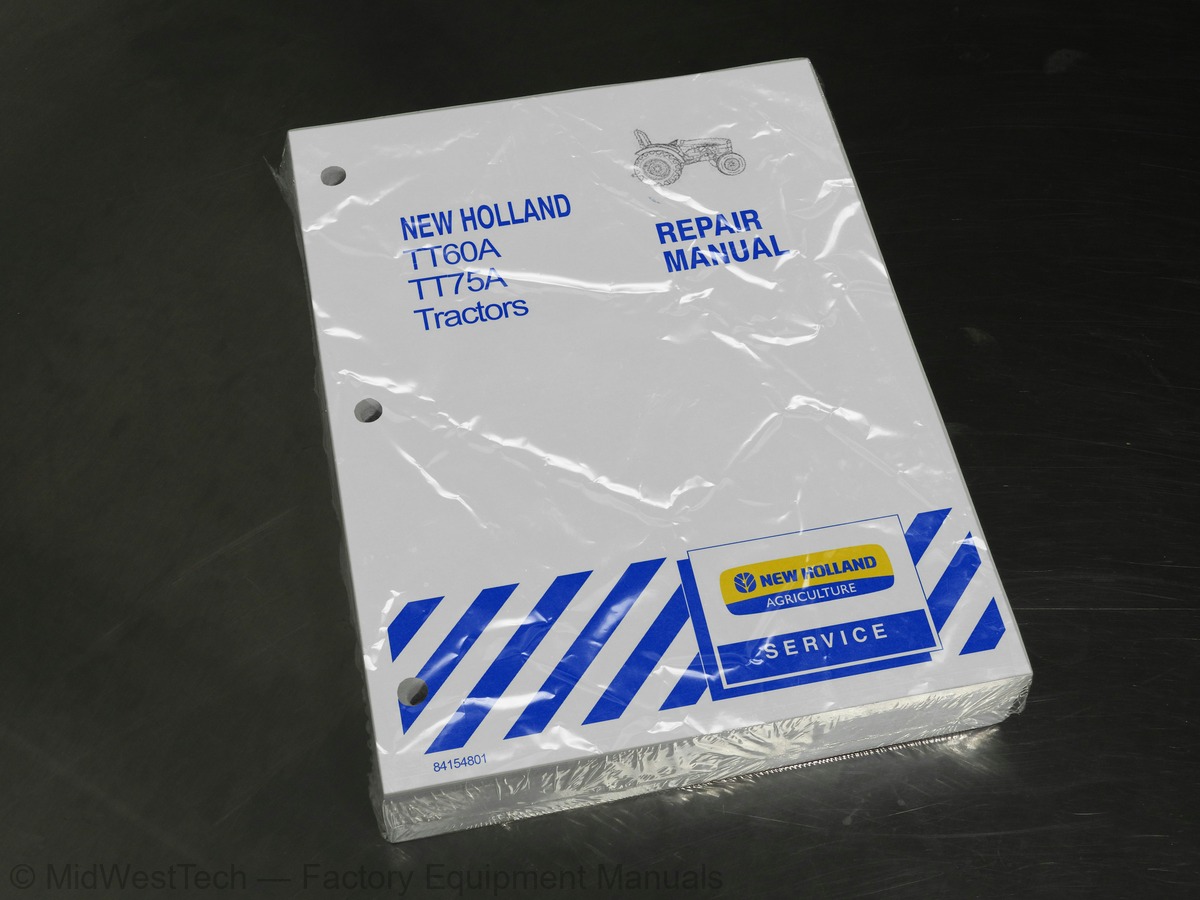
New Holland TT60A, TT75A Tractor Service Manual
709 pages · Publication 84154801
Added to your cart. View cart
What's inside
From the manual's own table of contents: 74 sections, 403 entries. See sample pages (PDF, 549 KB)
General Instructions11 topics
- Important Notice
- Shimming
- Rotating Shaft Seals
- O-Rings
- Sealers
- Bearings
- Spring Pins
- Precautionary Notice
- Equipment Notice
- Spare Parts Notice
- General Notices
Health and Safety4 topics
- Health and Safety Precautions
- General Workshop Tools and Equipment
- Legal Aspects
- Lubricants and Greases
Safety6 topics
- The Tractor
- Driving the Tractor
- Operating the Tractor
- Operating the PTO
- Servicing the Tractor
- Diesel Fuel
Safety Decals1 topic
- Instructional Decals
Show all 74 sections
Description and Operation -- Engine Components14 topics
- Cylinder Head Assembly
- Camshaft Assembly
- Cylinder Block Assembly
- Crankshaft Assembly
- Connecting Rods
- Pistons
- Manifolds
- Timing Gears
- Lubrication System
- Cooling System
- Fuel System
- Fuel Shut Off (Injection Pump)
- Lift Pump
- Fuel Filters
Engine Removal -- Installation3 topics
- Separating Engine from Transmission Housing
- Separating Front Axle from Engine
- Engine Installation
Engine Compression Test4 topics
- Test Procedure
- Test Readings
- Test Conclusion
- Rebuild Instructions
Overhaul38 topics
- Cylinder Head
- Removal
- Disassembly
- Repair and Inspection
- Injector Sleeves
- Valve Settings
- Valves
- Valve Guides
- Valve Springs
- Tappets and Pushrods
- Rocker Shaft
- Assembly
- Installation
- Front Engine Cover
- Timing Gear
- Idler Gear
- Fuel Pump Drive Gear
- Fuel Injection Pump Drive Gear
- Camshaft Drive Gear
- Hydraulic and Power Steering Pump Drive Gear
- Inspection and Repair
- Camshaft
- Camshaft Bearings
- Replacement
- Idler Gear Bushing
- Camshaft, Fuel Pump Drive Gear, Hydraulic and Power Steering Drive Gears
- Front Oil Seal
- Removal -- Installation
- Valve Timing -- TT60A/TT75A
- Adjustment
- Oil Pan
- Dynamic Balancer (TT75A Model only)
- Inspection and Installation
- Connecting Rods, Bearings, Pistons and Rings
- Connecting Rod Alignment
- Cylinder Block
- Flywheel
- Main Bearing and Crankshaft
Fuel System13 topics
- Air Cleaner
- Service the Engine Air Cleaner Outer Element
- Method A
- Method B
- Fuel Injection Pump
- Inspection
- Checking the Fuel Injection Pump Timing with Pump on the Tractor
- Lock-Time the Fuel Injection Pump with Pump Removed from the Tractor
- Fuel System Air Bleeding
- Injector
- Testing and Overhaul
- Fuel Pump
- Assembly and Installation
Lubrication System7 topics
- OIl Pump
- Oil Filter
- Oil Pressure Warning System
- Engine Oil Consumption Diagnosing Procedure
- Oil Consumption Test Procedure
- Compression Test
- Rework Instructions
Cooling System7 topics
- Radiator
- Thermostat
- Testing
- Water Pump
- Water Temperature Gauge
- Belt Tension Adjustment
- Description
Sectional Views3 topics
- Clutch Assembly
- Clutch Plate
- Longitudinal Section of 11 ″ /11 ″ LUK Clutch
Description and Operation11 topics
- Operation
- Clutch Mechanical Release Control
- Clutch Pedal
- PTO Clutch Lever
- Cross Shafts
- Transmission/PTO Release Bearing Assembly
- Transmission Clutch Pedal Free-Travel and Adjustment
- Adjusting PTO Clutch Linkage
- Release Fingers
- Release Lever Height Adjustment
- Important Points To Be Taken Into Account While Replacing Clutch
General Recommendations for Overhauling Operations38 topics
- Precaution at Flange and Tool Ends
- Reassembling Methods
- Recommendations Regarding Lubrication
- Shaft Seals
- O-ring
- Adjusting Shims
- Sealing
- Oil Drain
- Cleaning
- Inspections
- 8 + 2 Transmission
- Transmission Assembly
- Transmission -- Internal Components
- Drive Shaft Removal
- Drive Shaft Installation
- End Play Specification
- Gear Rails
- Special Tool Required
- Range Gear (Epi-Cyclic) Assembly
- Reverse Gears and Drive Shaft
- Driven Gears and Drive Shaft
- Checking Driven Gear Shaft Endplay
- Specifications
- External Components -- Gear Shift Lever
- Reverse Lever and Cover
- Front to Rear Axle Ratio
- Front Axle
- Steering Knuckle Pins and Bearings
- Stub Axle Adjustment
- Wheel Hub Bearing Adjustment
- Bevel Drive Adjustments
- Adjustment of the Preload of the Pinion Shaft Bearings
- Determining the Thickness of the Drive Pinion Position Adjustment Shim
- Ring/Pinion Adjustments
- Backlash Between the Pinion and Ring Gear
- Front Axle Differential
- End Float Adjustment
- Toe In Adjustment
Description of Operation4 topics
- Four-wheel Drive Lever
- Drive Shaft
- Transfer Box
- Intermediate Gear and Shaft
Description and Operation -- Mechanical Rear Wheel Drives12 topics
- Differential Lock
- Rear Wheel Drive Housing
- Differential Unit
- Pinion Shaft
- Shift Rails
- Adjustments and Settings
- Bevel Drive Shaft Bearing Preload Adjustment
- Bevel Pinion Shaft Depth Adjustment
- Assembling the Bevel and Pinion Shaft
- Differential Bearing Adjustment and Bevel Drive Backlash Check
- Differential Pinion and Side Gear Backlash Adjustment
- Adjustment of Ring Gear Bearings
Description and Operation -- Rear Axle and Final Drive3 topics
- Final Drive Housing
- Rear Axle Housing
- Rear PTO
Sectional View1 topic
- Power Take-Off
Adjustments4 topics
- PTO Clutch
- PTO Shaft Assembly
- PTO Assembly
- PTO Brake
Description and Operation -- Brake System4 topics
- Brake Pedals and External Linkages
- Parking Brake Linkage
- Brake Assembly
- Brake Pedal Free Play Adjustment
Introduction and Circuit Identification4 topics
- Pump
- Filter
- Mechanical Hydraulic Lift Assembly
- Remote Control Valve
Open Center Hydraulic Circuit and Mechanical Lift10 topics
- Schematic View of Hydraulic System
- Hydraulic Circuit Diagram
- Hydraulic Pump
- Hydraulic Pump Testing
- Inlet Restriction Test
- Pump Efficiency Test
- Relief Valve Test
- With or Without Rear Remote Valves
- Setting Relief Valve
- Servicing Faulty Relief Valve
Implement Attachments25 topics
- Hydraulic Lift
- Lift Hydraulic Control Valve
- Hydraulic System
- Pre-Operation Checks
- Position Control Operation
- Draft Control Operation (If Applicable)
- Combined Position and Draft Control Operation
- Float Operation
- Sensitivity Control
- Response Control
- Operation of Distributor
- Neutral Phase
- Lifting Phase
- Lowering Phase
- Internal Linkage System
- Position Control
- Float Control
- Draft Control
- Combined Draft and Position Control
- Mechanical Lift Assembly
- Rear Lift -- External Controls
- Hydraulic Lift -- Internal Controls
- Lift Arm Shaft (Cross Shaft)
- Seal Dimensions
- Distributor (Control Valve)
Adjustment and Settings2 topics
- Position Control Linkage Adjustment
- Maximum Lift Arm Travel Adjustment
Description of Operation -- Remote Control Valve(s)33 topics
- Remote Control Valve Oil Flow
- Single-Acting Valve without Automatic Detent Release
- Double-Acting Valve without Automatic Detent Release and Float Position
- Switching Valve
- Float, and Flow Control
- System Testing
- Steering Pump
- Steering Test
- Steering Relief Valve Pressure Test
- Relief Valve Adjustment -- All models
- Straight-Ahead Driving (A, a, d)
- LH Steer (B, Ss)
- Emergency Hydraulic Steer (C, Sed, Ses)
- Power Cylinder Safety and Make-up Valves (N2)
- Hydrostatic Steering Reservoir
- Inspection and Cleaning
- Steering Motor
- Inspection and Replacement
- Lubrication
- Assembly Pattern for Standard Bearing
- Installation of O-ring
- Installation of Lip Seal
- Two Wheel Drive Steering Cylinder
- FWD Steering Cylinder
- Front Axle Support
- Stub Assembly
- Front Axle Assembly
- Front Wheel Hub
- Spindle Assembly
- Overhaul
- Front Wheel Setting Tests
- Wheel Camber Test
- Front Wheel Toe-in Test
Description of Electrical System3 topics
- Component Location and Function
- Wiring Harnesses
- Grounds
Battery and Fuses6 topics
- Battery
- Checking the Battery Electrolyte Level
- Fuse Block
- Fuse Replacement
- Fuse Identification
- Fusible Link
Electrical System Components — Description and Testing20 topics
- Key Switch
- Key Switch Terminals
- Light Switch
- Terminal Identification
- Hazard Light Switch
- Hazard Switch
- Turn Signal Switch
- Transmission Range Safety Switch
- PTO Safety Switch
- Park Brake Safety Switch
- Seat Safety Switch
- Transmission Clutch Safety Switch
- Diodes
- Relays
- Description and Location
- Testing (Neutral Start)
- Hazard Flasher Cutoff)
- Hazard Flasher/Turn Signal Control Module
- Operator Safety Module
- Park Brake Safety Alarm (Buzzer)
Engine Sensors5 topics
- Engine Oil Pressure Sender
- Engine Coolant Temperature Sender
- KSB Temperature Switch
- Air Filter Restriction Switch
- Fuel Level Sender
Lighting4 topics
- Head Lamp
- Bulb Replacement
- Turn/Position Lights/Flasher
- Bulb Sizes
Charging Circuit18 topics
- Instrument Panel
- Instrument Panel, Gauges, and Warning Lights
- Left Turn Indicator
- Position Lights
- Head Light High Beam Indicator Light
- Engine Oil Pressure
- Battery Charging Indicator
- Right Turn Indicator
- Fuel Gauge
- Tachometer
- Hour Meter
- Air Cleaner Restriction Light
- Component Identification
- Component Testing and Replacement
- Temperature Gauge
- Instrument Panel Master Plugs Identification
- Circuit Diagram
- Instrument Panel Troubleshooting
Alternator2 topics
- Alternator Function
- Alternator
System Testing9 topics
- Starting System Test on Tractor
- Current Absorbed on the Starter Motor Circuit
- Starting System Circuit Resistance
- Voltage Drop
- Starter Motor
- Bench Tests
- Engine Hood Panel Assembly
- Rear Wheel Fenders
- Roll-Over Protection (ROPS) Bar
Inside this manual
Real pages from this service manual (709 pages). Open the sample pages (PDF, 548 KB)

- Color page
- Color page
Other manuals for this machine
Save 10% on 2 manuals, 15% on 3 or more. Other manuals for the TT60A, TT75A are listed below. Editions cover different serial number ranges: check the serial coverage and tick only the ones that match your machine.
Added to your cart. View cart
This is a service manual
Here's how it compares to the other manual types.
Service manual
Factory repair procedures and technical information such as specifications, troubleshooting, and wiring and hydraulic diagrams, for the models and systems the manual covers. See What's inside for its topics.
Operator's manual
Safe operation, controls, maintenance schedules, lubrication points, inspections, and basic checks. Repair procedures are in the service manual.
Parts manual
Illustrated diagrams with factory part numbers for identifying components and ordering parts. Repair procedures are in the service manual.
Engine service manuals are sometimes sold separately, since certain machine models were offered with more than one engine option.
What it's used for
Factory manual for in-house farm and construction shop use. Straightforward, complete, and easy to follow. It contains the OEM information dealership service departments and parts counters use to diagnose problems, identify components, and perform maintenance or repairs correctly.
Service shops and owner/operators who repair their own equipment
Identifying correct parts and seeing how assemblies come apart and go back together
Keeping equipment running with less downtime
Factory manual, 709 pages
Quantity one is the manual described above.
Fast free USA shipping
Ships in 1 business day.
60-day returns
Free if the mistake is ours. A manual ordered in error must come back unopened in its shrink-wrap; you pay return shipping and a 20% restocking fee applies. Return policy
Binder not included
Manuals over about 300 pages may need a standard 3-ring binder, which you can buy locally to keep the pages organized for shop use.
Questions about model, serial number, engine coverage or contents? Contact us before purchasing and we'll help confirm it's the right manual. Please verify the manual type, machine model, serial number range and engine coverage before purchasing: manuals ordered in error carry a 20% restocking fee (return policy).