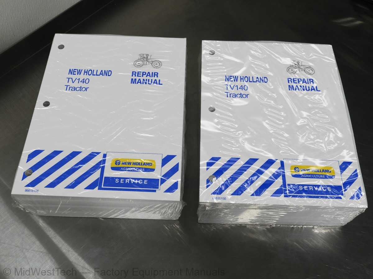
New Holland TV140 Tractor Service Manual
2,495 pages · Publication 86615156
Added to your cart. View cart
- Models
- TV140
- Manual type
- Service Manual
- Pages
- 2,495
- Publication
- 86615156
- Condition
- Brand new
What's inside
From the manual's own table of contents: 380 topics. See sample pages (PDF, 655 KB)
- 00 000 Precautionary Statements
- Safety Precautions
- General Considerations
- Tractor Identification
- Engine Identification
- Service Techniques
- Minimum Hardware Tightening Torques
- Standard Torque Data
- Recommended Lubricants and Coolants
- Recommended Sealants
- Specifications
- Bolt Torque Specifications
- Special Tools
- Air Induction System - Description and Operation
- Introduction
- Component Operation
- Troubleshooting
- Turbocharger Boost Testing
- Air Induction System - Removal and Repair of Components
- Turbocharger Intake Tube
- Turbocharger Outlet Tube
- Air Filter Housing, Precleaner, and Air Induction Scoop
- Turbocharger
- Repair Time Schedule
Show all 380 topics
- Exhaust System - Description of Operation
- Exhaust System Component Removal and Repair
- Exhaust Muffler and Stack
- Engine Specifications
- Torque Values
- Description and Operation
- Cylinder Head Assembly
- Camshaft Assembly
- Connecting Rods
- Pistons
- Manifolds
- Cylinder Block Assembly
- Timing Gears
- Lubrication System
- Dynamometer Engine Testing
- Dynamometer Engine Break In
- Compression Test
- Engine Overhaul
- Engine Removal
- Engine Disassembly
- Engine Component Disassembly, Inspection, and Assembly
- Front Timing Gears, Oil Pan, Camshaft, and Valve Tappets (Lifters)
- Pistons and Connecting Rods
- Crankshaft and Main Bearings
- Oil Pump and Sump Tube
- Oil Cooler/Filter Support Assembly
- Flywheel
- Engine Assembly
- Engine Installation
- Repair Time Schedule – Engine Overhaul
- Cooling System Description and Operation
- Individual Component Operation
- Cooling System Troubleshooting
- Cooling System Testing
- Cooling System Tests
- Cooling System - Removal and Repair of Components
- Radiator
- Thermostat
- Cooling Fan (North American Models)
- Cooling Fan and Viscous Clutch (International Models)
- Fan Belt Tensioner
- Water Pump
- Repair Time Schedule - Cooling System
- TV140 Fuel Injection Pump Test Plan
- Fuel System – Description and Operation
- Fuel Injection Pump
- Engine Shutoff
- Injector Nozzle Testing
- Fuel System Service
- Bleeding The Fuel Injection System
- Fuel Injectors
- Bosch VE Fuel Injection Pump
- Electric Lift Pump
- Fuel Sedimenter
- Fuel Filter
- Fuel Tanks
- Crossover Tube
- Cold Start System – North American Models
- Cold Start System – International Models
- Throttle Cable
- Repair Time Schedule -- Fuel System
- Orientation
- Splitter Box
- Hydrostatic Drive Description
- Torque Specifications
- Safety
- Power Flow
- Description of Operation
- Splitter Box Description
- Splitter Box Gear Sets
- Hydrostatic and Hydraulic System Components
- Moving a Disabled Tractor
- Troubleshooting and Testing
- Pressure Testing
- Range Select Control Switch and Valve
- Overhaul
- Removal and Installation
- Auxiliary Pump
- Disassembly, Inspection, and Repair
- Auxiliary Drive Housing
- Auxiliary 3/4 ″ Couplers
- Articulation Joint Drive Shafts
- Upper Drive Shaft
- Engine Power Input Shaft
- Lower Drive Shaft
- Splitter Box Power Input (Top) Shaft
- Splitter Box Power Output (Bottom) Shaft
- Engine-end Axle Drive Shaft
- Tapered Bearing End Play Check and Adjustment
- Hydrostatic Motor
- Hydrostatic Pump
- FNR Lever Cables
- Specification
- Axle Shaft Preload
- Axle Shaft Spacer Selection Table
- Differential Bearing Preload
- Differential Bearing Shim Table
- Drive Pinion Preload
- Drive Pinion Spacer Table
- Tightening Torques
- Drive Path
- Drive Pinion
- Differential
- Planetary Assembly
- Axle Shaft and Trumpet Housing
- Differential Lock
- Disassembly and Repair
- Trumpet/Axle Disassembly
- Planetary Disassembly
- Planetary Inspection
- Planetary Reassembly
- Planetary Ring Gear Removal
- Planetary Ring Gear Installation
- Trumpet/Axle Inspection
- Trumpet/Axle Reassembly
- Pinion Gear Removal
- Pinion Gear Disassembly
- Pinion Gear Inspection
- Center Housing Inspection
- Pinion Gear Reassembly
- Pinion Bearing Preload
- Pinion Gear Installation
- Differential Disassembly
- Differential Inspection
- Differential Reassembly
- Differential Lock Internal Operating Components Overhaul
- Differential Lock Valve and Tube Removal
- Differential Lock Valve and Tube Inspection
- Differential Lock Valve and Tube Installation
- Oscillating Components
- Rear Trunnion Inspection
- Rear Trunnion Installation
- Front Trunnion Removal
- Front Trunnion Inspection
- Front Trunnion Installation
- Diff Lock Switch Removal
- Diff Lock Switch Inspection
- Diff Lock Switch Installation
- Apply Solenoid and Valve Removal
- Apply Solenoid and Valve Inspection
- Apply Solenoid and Valve Installation
- Breather Removal
- Breather Inspection
- Breather Installation
- 27 000 Specifications
- Overview
- Cab-End PTO Clutch Control Valve Operation
- Cab-End Output Drive
- Electrical Operation
- Cab-End PTO Electrical Circuit
- Preliminary Procedures
- Cab-End PTO Clutch
- Cab-End PTO Shafts and Gears
- PTO Switch
- Engine-End PTO Electrical Circuit
- Engine-End Output Drive
- Clutch and Brake Pressure Apply
- Lubrication Flow
- Breather Lines
- Testing PTO Gearbox Drain Pump Flow
- Engine-End PTO Gearbox Overhaul
- PTO Transfer Shaft and Coupler
- Clutch Pressure Apply Hose
- Lube Motor
- Lube Circuit Hose
- Breather and Hose
- Apply Solenoid and Valve
- Brake
- Adjustments
- Removal and Installation of Components
- Brake Disc Components
- Foot Pedal Linkage
- Master Cylinder
- Reservoir
- Hose - Reservoir To Master Cylinder
- Tubes - Pressure Supply
- Park Brake Lever
- Park Brake Cables and Links
- Brake Pedal Switch
- Park Brake Switch
- Auxiliary Hydraulics
- Component Identification
- Hydraulic Circuits
- Steering Control Valve
- Implement Pump
- Implement Valve
- Priority (Inlet) Valve Section
- Tan (Float) Valve Section
- Blue (Detent) Valve Section
- Green (Standard) Valve Section
- 1/2 ″ Couplers
- Implement Valve Control Linkage
- Control Lever Cable
- Control Pedal Assembly
- Control Pedal Cable
- In Cab Flow Control Cables
- Hydraulic System Hoses
- 3/4 ″ Couplers
- Hydraulic Oil Heater
- Engine End Remote Valves
- Hydraulic Oil Cooler
- Hydraulic Oil Cooler By-pass
- Three-Point Hitch Electrical Control Components
- Three-Point Hitch Electrical Control System
- Neutral – Manual Mode
- Raise – Manual Mode
- Lower – Manual Mode
- Raise – Manual Mode – Fender Switches
- Lower – Manual Mode – Fender Switches
- Neutral – Automatic Mode
- Raise – Automatic Mode
- Lower – Automatic Mode
- Raise – Automatic Mode – Fender Switches
- Lower – Automatic Mode – Fender Switches
- Float – Automatic Mode
- Float Position Control – Automatic Mode
- Hydraulic Lift Assembly Control Valve
- Three-Point Hitch Controller Fault Codes
- Electrical
- Hydraulics
- Calibration Mode
- Upper Limit Operating Set Point Adjustment
- Removal and Repair of Components
- Raise/Lower Switches
- Automatic/Manual Switch
- Status Light
- Depth Control Potentiometer
- Lowering Rate Potentiometer
- External Three-Point Hitch Controls
- Feedback Potentiometer
- Hydraulic Lift Cover
- Lift Cylinder
- Cross Shaft
- Control Valve
- Upper Lift Link
- Lower Lift Link Stabilizer Assembly
- Lower Lift Link
- Lift Assist Ram
- Flexible Link Ends
- Link Assembly
- Manual Mode
- Automatic Mode
- Center Lift Link
- Stabilizer Assembly
- Hydraulic Cylinders
- Lift Link Assembly
- Proper Jacking
- Tire Inflation
- Tire and Wheel Options
- Ballasting and Tires
- Wheel Slippage
- Ballast Limitations
- Ballasting Recommendations
- Cast Iron Weights
- Liquid Ballast Calculations
- Torques
- Engine Hood
- Hood Support Assembly
- Side Panels, Right-hand and Left-hand
- Front Grille
- Cab-end Fenders
- Left-hand and Right-hand
- Engine-end Fenders
- Heatshield
- Engine End Drawbar
- Cab End Drawbar
- Front Axle Support
- Frame Side Rails
- Steering Pins
- Pivot Pins
- Front Frame
- Rear Frame
- R134a Refrigerant Information
- The Basics of Refrigeration
- Compressor and Clutch
- Condenser
- Receiver-drier
- Thermal Expansion Valve
- Evaporator/Heater Assembly
- Blower Motor Assembly
- Thermostatic Switch
- High and Low Pressure Switches
- Heater Control Valve
- Switched Power: Fuses and HVAC Relay
- Air Filtration
- General Safety and Service Precautions
- Recovering R134a Refrigerant With OEM1598
- System Evacuation and Recharging With OEM1598
- Oil Level Check Or Adjustment
- Leak Detection
- Performance Testing
- Pressure/Temperature Relationship Chart
- Conditions For Performance Testing
- Gauge Readings and Interpretations
- Performance Test and Diagnosis Summary
- General Troubleshooting Summary
- Heating System
- Air Conditioning System
- Air-conditioning Component Removal and Installation
- Compressor
- Compressor Clutch
- Air Conditioning Hoses
- Recirculation Door Control
- Blower Speed Control
- Heater Hoses
- Fuse and Relay Panel
- Electrical System
- Using Schematics
- Circuit Troubleshooting
- Temporary Wiring Harness Repair
- Batteries
- Starting and Charging Systems
- Starter
- Batteries Troubleshooting
- Starter Troubleshooting
- EICS Error Codes
- EICS Connector Chart
- Alarms
- Three-Point Hitch Controller
- Electrical Wiring Diagrams
- Schematic Index
- Alternator
- Electronic Instrument Contol System (EICS)
- Connectors
- Repairing Connectors
- Lamp Replacement
- Harness Removal and Installation
- Italian Brake Harness
- Electrical Kits and Accessories
- Frame and Platform
- Hydraulic and PTO Kits
- Loader Kits and Accessories
- 90 000 Specifications
- Cab Mounts
- Cab Roof
- Taillight Panel
- Cab Fenders
- Wiper Motor Cover
- Windshield Wipers
- Doors
- Cab Door Lock and Latch
- Lock Cylinder
- Window Latch
- Door Glass
- Side Windows
- Floor Mats
- Seat Console
- Fender Well Covers
- Seat
- Console Assembly
- Steering Logic Valve Trip Linkage
- Rotating Grommet Assembly
- Headliner
- Louvers
- Radio and Speakers
- Calibration (Adjustments)
Inside this manual
Real pages from this service manual (2,495 pages). Open the sample pages (PDF, 654 KB)

- Specifications, page 254: SECTION 10 -- ENGINE -- CHAPTER 2
- Diagram, page 2,230: SECTION 55 -- ELECTRICAL SYSTEM -- CHAPTER 2
- Repair procedure, page 2,382: SECTION 90 -- CAB -- CHAPTER 1
- Color page, page 907
- Foldout diagram (color), page 903
Other manuals for this machine
Save 10% on 2 manuals, 15% on 3 or more. Other manuals for the TV140 are listed below. Editions cover different serial number ranges: check the serial coverage and tick only the ones that match your machine.
Added to your cart. View cart
This is a service manual
Here's how it compares to the other manual types.
Service manual
Factory repair procedures and technical information such as specifications, troubleshooting, and wiring and hydraulic diagrams, for the models and systems the manual covers. See What's inside for its topics.
Operator's manual
Safe operation, controls, maintenance schedules, lubrication points, inspections, and basic checks. Repair procedures are in the service manual.
Parts manual
Illustrated diagrams with factory part numbers for identifying components and ordering parts. Repair procedures are in the service manual.
Engine service manuals are sometimes sold separately, since certain machine models were offered with more than one engine option.
What it's used for
Factory manual for in-house farm and construction shop use. Straightforward, complete, and easy to follow. It contains the OEM information dealership service departments and parts counters use to diagnose problems, identify components, and perform maintenance or repairs correctly.
Service shops and owner/operators who repair their own equipment
Identifying correct parts and seeing how assemblies come apart and go back together
Keeping equipment running with less downtime
Factory manual, 2,495 pages
Quantity one is the manual described above.
Fast free USA shipping
Ships in 1 business day.
60-day returns
Free if the mistake is ours. A manual ordered in error must come back unopened in its shrink-wrap; you pay return shipping and a 20% restocking fee applies. Return policy
Binder not included
Manuals over about 300 pages may need a standard 3-ring binder, which you can buy locally to keep the pages organized for shop use.
Questions about model, serial number, engine coverage or contents? Contact us before purchasing and we'll help confirm it's the right manual. Please verify the manual type, machine model, serial number range and engine coverage before purchasing: manuals ordered in error carry a 20% restocking fee (return policy).