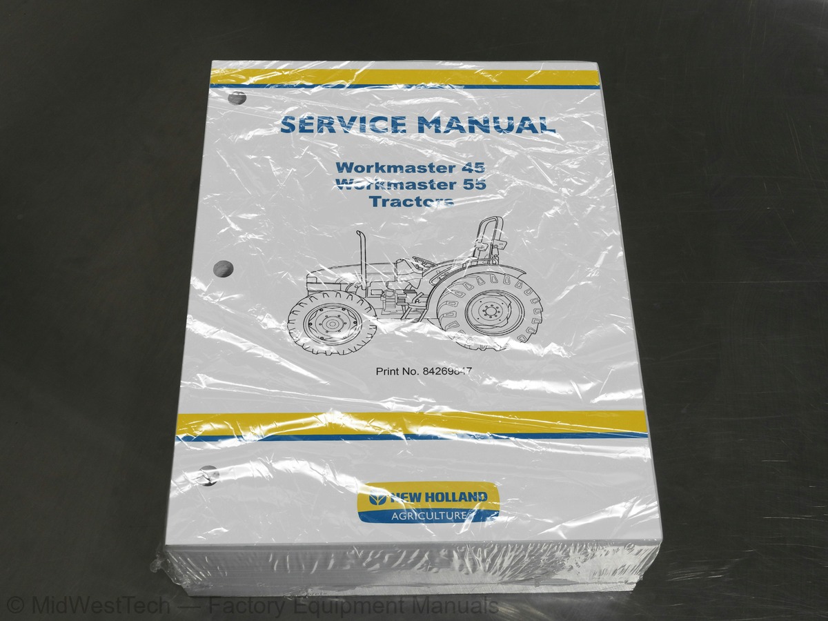
New Holland Workmaster 45, 55 Tractor Service Manual
883 pages · Publication 84269847
Added to your cart. View cart
- Models
- Workmaster 45, 55
- Manual type
- Service Manual
- Pages
- 883
- Publication
- 84269847
- Condition
- Brand new
What's inside
From the manual's own table of contents: 290 topics. See sample pages (PDF, 607 KB)
- PRIMARY HYDRAULIC POWER SYSTEM
- PRIMARY HYDRAULIC POWER SYSTEM Open center mechanical remote valve
- HYDRAULIC COMMAND SYSTEM
- ELECTRICAL POWER SYSTEM
- LIGHTING SYSTEM
- ENGINE AND PTO IN
- ENGINE
- FUEL AND INJECTION SYSTEM
- AIR INTAKE SYSTEM
- EXHAUST SYSTEM
- ENGINE COOLANT SYSTEM
- LUBRICATION SYSTEM
- STARTING SYSTEM
- TRANSMISSION, DRIVE AND PTO OUT
- POWER COUPLING Clutch
- TRANSMISSION Mechanical
- REAR PTO Mechanical
- AXLES, BRAKES AND STEERING
- FRONT AXLE
- REAR AXLE
- 2WD-4WD SYSTEM Mechanical
- STEERING Hydraulic
- SERVICE BRAKE Mechanical
- PARKING BRAKE Mechanical
Show all 290 topics
- FRAME AND CAB
- SHIELD
- USER CONTROLS AND SEAT
- Foreword
- Foreword Ecology and the Environment
- Legal advice
- International symbol
- Safety rules
- Basic instructions Hardware
- Torque Specification Tables
- General specification
- General specification - Biodiesel Fuels
- Dimension
- Consumables
- Product identification
- Torque
- Sealing
- Special tools
- Component identification - Introduction and circuit identification
- Hydraulic schema Open center hydraulic circuit and mechanical lift
- Static description
- Dynamic description Rear remote valves - Optional
- Static description with filter
- Static description Auxiliary hydraulic ports
- Dynamic description
- Remove Mechanical lift assembly
- Disassemble - Rear lift internal controls
- Inspect Rear lift internal controls
- Assemble Rear lift internal controls
- Install Mechanical lift assembly
- Disassemble Lift arm shaft
- Inspect Lift arm shaft
- Assemble Lift arm shaft
- Check Hydraulic system pressure check
- Pressure test Setting relief valve
- Component localisation Electrical component location and Function
- Wiring schema Charging circuit
- Static description Diodes
- Static description Relays
- Electrical schematic frame 01 - sheet 01
- Electrical schematic frame 02 - sheet 02
- Electrical schematic frame 03 - sheet 03
- Electrical schematic frame 04 - sheet 04
- Electrical schematic frame 05 - sheet 05
- Electrical schematic frame 06 - sheet 06
- Electrical schematic frame 07 - sheet 07
- Electrical schematic frame 08 - sheet 08
- Electrical schematic frame 09 - sheet 09
- Electrical schematic frame 10 - sheet 10
- Electrical schematic frame 11 - sheet 11
- Electrical schematic frame 12 - sheet 12
- Electrical schematic frame 13 - sheet 13
- Wiring schema Safety start circuit - Operator present
- Wiring schema Safety circuit start circuit - Operator not present
- Wiring schema Safe operation - Operator present
- Wiring schema Safe operation - Operator not present, PTO "OFF
- Wiring schema Safe operation - Operator not present, PTO “ON
- Static description Light switch
- Static description Lighting circuit
- Static description Hazard light switch
- Static description Turn light switch
- Static description Hazard lighting circuit
- Static description Right turn signal circuit
- Static description Left turn signal circuit
- Static description Hazard flasher/Turn signal control module
- Remove Light switch
- Test Light switch
- Install Light switch
- Replace Bulb replacement
- Replace Head lamp
- Remove Hazard light switch
- Test Hazard light switch
- Install Hazard light switch
- Remove Turn signal switch
- Test Turn signal switch
- Install Turn signal switch
- Remove Hazard flasher/Turn signal control module
- Test Hazard flasher/Turn signal control module
- Install Hazard flasher/Turn signal control module
- Troubleshooting Lighting circuit
- Identification
- Remove Separating the tractor at the clutch housing/engine - 8x8 transmission
- Remove Separating the tractor at the engine/frame
- Install - To frame
- Install - Attaching the tractor at the clutch housing/engine - 8x8 transmission
- Disassemble
- Inspect
- Assemble
- Inspect - Valve seats
- Inspect - Valves
- Inspect - Valve guides
- Inspect - Valve springs
- Inspect - Rocker arms
- Calibration
- Overview Governor
- Dynamic description Solenoid
- Dynamic description Fuel variation mechanism
- Dynamic description (Delivery Valve Assembly)
- Dynamic description (Compact Timing Device Mechanism)
- Dynamic description Pumping Elements
- Dynamic description Delivery Valves
- Static description Fuel level sender
- Disassemble Governor
- Assemble Governor
- Adjust Governor
- Remove Solenoid
- Test Solenoid
- Install Solenoid
- Remove
- Install
- Dynamic description - Radiator cap
- Static description Engine coolant temperature sending unit
- Service instruction
- Overhaul
- Test
- Install with cooling fan
- Test Engine coolant temperature sending unit
- General specification Engine
- Dynamic description Engine breather valve
- Dynamic description Engine oil pressure switch
- Check - Oil Consumption
- Pressure test Engine oil
- Remove - Suction pipe and strainer
- Install Oil suction pipe and suction strainer
- Remove Engine breather valve
- Install Engine breather valve
- Test Engine oil pressure switch
- General specification Starter motor
- Static description Key Switch
- Install Glow plug and connector
- Disassemble Starter motor
- Inspect Starter motor
- Electrical test Starter motor
- Assemble Starter motor
- Electrical test No Load
- Install Starter motor
- Test Key switch
- Electrical test
- Troubleshooting
- Sectional view Clutch Assembly
- Sectional view Clutch plate
- Remove Clutch Assembly
- Install Clutch Assembly
- Disassemble Clutch Assembly
- Inspect Clutch Assembly
- Assemble Clutch Assembly
- Replace Clutch Assembly
- Remove Clutch pedal
- Inspect Clutch pedal
- Install Clutch pedal
- Adjust Clutch pedal setting
- Disassemble Release Fingers
- Assemble Release Fingers
- Adjust Release lever height adjustment
- Sectional view
- Static description 8 X 8 Shuttle Transmission
- Static description Transmission range safety switch
- Static description Transmission clutch safety switch
- Remove Transmission assembly
- Disassemble Intermediate plate
- Inspect Intermediate plate
- Assemble Intermediate plate
- Install Transmission assembly
- Remove Gear Shift Lever
- Install Gear Shift Lever
- Remove Transmission Driven and Drive Shaft
- Disassemble Transmission Drive Shaft
- Inspect Transmission Drive Shaft
- Disassemble Transmission Driven Shaft
- Inspect Transmission Driven Shaft
- Install Transmission Driven and Drive Shaft
- Remove Transmission Range Shaft
- Inspect Transmission Range Shaft
- Remove Transmission Pinion shaft
- Static description PTO Safety switch
- Remove Main PTO Levers and Internal Linkages
- Inspect Main PTO Levers and Internal Linkages
- Install Main PTO Levers and Internal Linkages
- Remove PTO and Clutch lever cross shaft
- Inspect PTO and Clutch lever cross shaft
- Install PTO and Clutch lever cross shaft
- Disassemble Transmission/PTO Release Bearing Assembly
- Assemble Transmission/PTO Release Bearing Assembly
- Remove Main PTO Shafts
- Disassemble Rear PTO Shaft Assembly
- Inspect Rear PTO Shaft Assembly
- Assemble Rear PTO Shaft Assembly
- Install Main PTO Shafts
- Adjust PTO Clutch Adjustment
- Test PTO Brake Torque Test
- Test PTO Safety switch
- General specification - 2WD
- Torque - 2WD
- Sealing - 2WD
- General specification - 4WD
- Torque - 4WD
- Special tools - 4WD
- Sectional view - 2WD
- Static description - 2WD
- Dynamic description - 4WD
- Sectional view - 4WD
- Adjust Track
- Remove - 2WD
- Install - 2WD
- Test Front wheel setting tests
- Remove - 4WD
- Install - 4WD
- Disassemble - 4WD
- Inspect - 4WD
- Assemble - 4WD
- Adjust - 4WD Ring/pinion adjustment
- Adjust - 4WD Toe in adjustment
- Adjust - Stub axle adjustment 4WD
- Remove Housing - Left-hand side or right-hand side
- Disassemble Housing - Left-hand side or right-hand side
- Install Housing - Left-hand side or right-hand side
- Backlash
- Remove Ring gear and differential assembly
- Install with differential housing
- Remove Transfer box
- Disassemble Transfer box
- Assemble Transfer box
- Install Transfer box
- Static description Hydrostatic steering reservoir
- Remove Steering Motor
- Disassemble Steering Motor
- Inspect Steering Motor
- Assemble Steering Motor
- Install Steering Motor
- Adjust
- Pressure test
- Inspect Hydrostatic steering reservoir
- Remove Two wheel drive steering cylinder
- Disassemble Two wheel drive steering cylinder
- Assemble Two wheel drive steering cylinder
- Install Two wheel drive steering cylinder
- Remove - Four wheel drive steering cylinder
- Disassemble - Four wheel drive steering cylinder
- Inspect - Four wheel drive steering cylinder
- Remove Brake pedals and external linkages
- Install Brake pedals and external linkages
- Adjust Free play
- Static description Park brake safety switch
- Static description Park brake safety alarm - Buzzer
- Remove Parking brake
- Install Parking brake
- Test Park brake safety switch
- Remove Park brake safety alarm - Buzzer
- Test Park brake safety alarm - Buzzer
- Install Park brake safety alarm - Buzzer
- USER PLATFORM
- SAFETY SECURITY ACCESSORIES Safety
- Remove PANEL ASSEMBLY
- Install PANEL ASSEMBLY
- Remove REAR WHEEL FENDERS
- Install REAR WHEEL FENDERS
- Component identification Instrument Panel Master Plugs Identification
- Functional diagram
- Static description Seat safety switch
- Static description Operator safety module
- Remove Seat safety switch
- Test Seat safety switch
- Install Seat safety switch
- Remove Operator safety module
- Test Operator safety module
- Install Operator safety module
Inside this manual
Real pages from this service manual (883 pages). Open the sample pages (PDF, 607 KB)
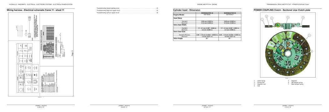
- Diagram, page 142: Wiring harness - Electrical schematic frame 11 - sheet 11
- Troubleshooting, page 194
- Specifications, page 246: ENGINE AND PTO IN - ENGINE
- Color page: TRANSMISSION, DRIVE AND PTO OUT - POWER COUPLING Clutch
Other manuals for this machine
Save 10% on 2 manuals, 15% on 3 or more. Other manuals for the Workmaster 45, 55 are listed below. Editions cover different serial number ranges: check the serial coverage and tick only the ones that match your machine.
Added to your cart. View cart
This is a service manual
Here's how it compares to the other manual types.
Service manual
Factory repair procedures and technical information such as specifications, troubleshooting, and wiring and hydraulic diagrams, for the models and systems the manual covers. See What's inside for its topics.
Operator's manual
Safe operation, controls, maintenance schedules, lubrication points, inspections, and basic checks. Repair procedures are in the service manual.
Parts manual
Illustrated diagrams with factory part numbers for identifying components and ordering parts. Repair procedures are in the service manual.
Engine service manuals are sometimes sold separately, since certain machine models were offered with more than one engine option.
What it's used for
Factory manual for in-house farm and construction shop use. Straightforward, complete, and easy to follow. It contains the OEM information dealership service departments and parts counters use to diagnose problems, identify components, and perform maintenance or repairs correctly.
Service shops and owner/operators who repair their own equipment
Identifying correct parts and seeing how assemblies come apart and go back together
Keeping equipment running with less downtime
Factory manual, 883 pages
Quantity one is the manual described above.
Fast free USA shipping
Ships in 1 business day.
60-day returns
Free if the mistake is ours. A manual ordered in error must come back unopened in its shrink-wrap; you pay return shipping and a 20% restocking fee applies. Return policy
Binder not included
Manuals over about 300 pages may need a standard 3-ring binder, which you can buy locally to keep the pages organized for shop use.
Questions about model, serial number, engine coverage or contents? Contact us before purchasing and we'll help confirm it's the right manual. Please verify the manual type, machine model, serial number range and engine coverage before purchasing: manuals ordered in error carry a 20% restocking fee (return policy).