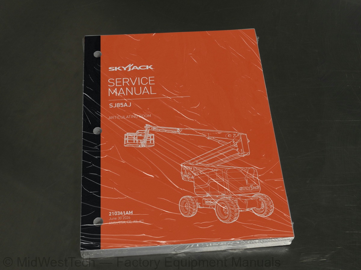
Skyjack SJ85AJ Articulating Boom Lift Service Manual
217 pages · Publication 210341AM
Added to your cart. View cart
- Models
- SJ85AJ
- Serial coverage
- SJ85AJ: 95400001 to 95499999
- Manual type
- Service Manual
- Pages
- 217
- Publication
- 210341AM
- Condition
- Brand new
What's inside
From the manual's own table of contents: 5 sections, 208 entries. See sample pages (PDF, 840 KB)
Section 1 – Scheduled Maintenance30 topics
- Read and Heed
- 1.1-1 Mobile Elevating Work Platform (MEWP) Definition
- 1.1-2 Purpose of Equipment
- 1.1-3 Use of Equipment
- 1.1-5 Service Policy and Warranty
- 1.1-6 Operator Safety Reminders, Warnings and Precautions
- Maintenance and Service
- 1.2-1 Maintenance and Inspection Schedule
- 1.2-2 Owner’s Annual Inspection Record
- 1.2-3 Replacement Parts
- 1.2-4 Maintenance and Service Safety Tips
- 1.2-5 Hydraulic System & Component Maintenance and Repair
- 1.2-6 Hydraulic Maintenance Hints
- 1.2-7 Railing Maintenance and Repair
- Scheduled Maintenance
- 1.3-1 Service Bulletins
- 1.3-2 Maintenance and Inspection
- 1.3-3 Maintenance Instructions
- Owner’s Annual Inspection Record
- Pre-Delivery/Maintenance Inspection Checklist
- Scheduled Maintenance Inspections
- 1.6-2 Electrical
- 1.6-3 Limit Switches
- 1.6-4 Hydraulic
- 1.6-5 Engine Compartment
- 1.6-6 Control Compartment
- 1.6-8 Platform Assembly
- 1.6-9 Boom Assembly
- 1.6-10 Optional Equipment/Attachments
- Function Tests
Section 2 – Maintenance Tables and Diagrams16 topics
- Standard Hose Numbering System
- Torque Specifications for Fasteners (US)
- Torque Specifications for Fasteners (Metric)
- Torque Specifications for Hydraulic Couplings & Hoses
- Axle Torque Specifications
- Axle Maintenance Intervals
- MEWP Torque Specifications
- Tire Specifications
- Floor Loading Pressure
- Specifications & Features - Dimensional Data
- Specifications and Features - Performance & Speeds
- Hydraulic Specifications
- Specifications and Features - Engines & Fluids
- Reach Diagram
- Dimensions
- Axle Oscillation Zones
Section 3 – System Component Identification and Schematics45 topics
- Electrical Symbol Chart
- Hydraulic Symbol Chart
- Wire Number and Color Code
- Wire Numbers and Color Codes - Additional
- Hydraulic Parts List
- Electrical Parts List
- Brake Manifold Port Identification
- Jib Manifold Port Identification
- Main Manifold - Hose Port Identification
- Main Manifold - Hydraulic Components
- Main Manifold - Electrical Components
- SGE Harness Connection
- Platform & Jib Harness Connection
- Footswitch Harness Connection
- Main Manifold Harness
- Platform to Base Control Cables
- Limit Switch Connections - Base Control Box
- Engine Control Wiring - Deutz TD2.9L
- Engine Control Wiring - Deutz D2011
- Engine Control Wiring - Kubota WG3800
- Engine Control Wiring - Perkins 2.2TA
- Anti-Overrising Limit Switch Harnesses - KC
- Deutz EDC-F Harness
- Load Cell Wiring
- Hydraulic Schematic
- Electrical Schematic - ANSI/CSA & AS (serial number 95400457 and below)
- Electrical Schematic - ANSI/CSA & AS (serial number 95400458 and above)
- Electrical Schematic - CE (serial number 95400457 and below)
- Electrical Schematic - CE (serial number 95400458 and above)
- Electrical Schematic - KC (serial number 95400457 and below)
- Electrical Schematic - KC (serial number 95400458 and above)
- Platform Controls Wiring
- Platform Controls - Harness View
- Platform Controls - Schematic View
- Base Controls Wiring - ANSI/CSA & AS
- Base Controls Wiring - ANSI/CSA with Positive Air Shut-off Option
- Torque Specifications for Fasteners (Metric)
- Base Controls Wiring - KC
- Engine Schematic - Deutz TD2.9L
- Engine Schematic - Deutz D2011
- Engine Schematic - Perkins 2.2TA
- Engine Schematic - Kubota WG3800
- Engine Harness - Deutz TD2.9L
- Engine Harness - Perkins 2.2TA
- Engine Harness - Kubota WG3800
Section 4 – Troubleshooting Information30 topics
- Introduction
- Electrical System
- 4.2-1 All Controls Inoperative
- 4.2-3 Engine will not Crank
- 4.2-4 No Boom Up or Down
- 4.2-5 No Riser Up or Down
- 4.2-6 No Turret Rotate
- 4.2-7 No Telescope
- 4.2-8 No Platform Level
- 4.2-9 No Jib Up or Down
- 4.2-10 No Platform Rotate
- 4.2-11 No Platform Rotate or Jib Functions
- 4.2-12 No Drive or Steer
- 4.2-13 Direction Sensing Inoperative
- 4.2-14 Green LED on Load Sense/Dual Load Zone Module is not On
- 4.2-15 Load Sense Indicates Overload or Overload Warning with Platform Empty or Below Weight
- 4.2-16 Load Sense/Dual Load Zone Module Error
- 4.2-17 No Light/Alarm when Platform is Overloaded
- Hydraulic System
- 4.3-1 All Controls Inoperative
- 4.3-2 All Boom Functions Inoperative
- 4.3-3 No Main Boom Up or Down
- 4.3-4 No Turret Rotate
- 4.3-5 No Boom Extend or Retract
- 4.3-6 No Riser Up or Down
- 4.3-7 No Platform Level
- 4.3-8 No Jib Up or Down
- 4.3-9 No Platform Rotate
- 4.3-12 No Brake Function
- 4.3-13 No Oscillating Axle Function
Section 5 – Procedures82 topics
- General
- 5.1-1 Safety and Workmanship
- System Control Module (SCM)
- 5.2-1 User Interface Keys
- 5.2-2 SCM Character Functions
- 5.2-3 SCM Operating Values
- 5.2-4 How to select SCM Functionality
- 5.2-5 How to Unlock and Modify SCM Settings
- 5.2-6 Check I/O Error
- Platform
- 5.3-1 Fly Boom Switch Voltage References
- 5.3-2 Platform Controller Voltage References
- 5.3-3 Remove the Platform
- 5.3-4 Reinstall the Platform
- 5.3-5 Replace the Load Cell
- Boom
- 5.4-1 Check the Wear Pads
- 5.4-2 Shim the Wear Pads
- 5.4-3 Torque the Rotary Actuator Bolts
- 5.4-4 Remove the Jib
- 5.4-5 Install the Jib
- 5.4-6 Limit Switch Locations
- Turret
- 5.5-1 Checkand Replace the High Pressure Filter
- 5.5-2 Adjust the Turret Rotation Gear Backlash
- 5.5-3 Check the Swing Drive Oil
- 5.5-4 Change the Swing Drive Oil
- 5.5-5 Replace the Battery
- 5.5-6 Turret Rotation Gear Bolt Torque Sentence
- 5.5-7 Electronic Tilt Switch Setup
- 5.5-8 Check the Rotation Bearing for Axial Wear
- 5.5-9 Reset the Emergency Lowering Counter (CE only)
- Deutz Diesel Engines
- 5.6-1 Replace the Engine Oil and Filter
- 5.6-2 Replace the Fuel Filter
- 5.6-3 Replace the Air Filter
- 5.6-4 Check the Engine Belt
- 5.6-5 Checking the Oil Cooler (Deutz D2011 only)
- Hydraulic Tank
- 5.7-1 Change the Hydraulic Tank Filter
- 5.7-2 Change the Hydraulic Oil
- Manifolds and Hydraulic Pumps
- 5.8-1 Hydraulic Brake Pressure Adjustment
- 5.8-2 Hydraulic Standby Pressure Adjustment
- 5.8-3 Hydraulic High Pressure Adjustment
- 5.8-4 Hydraulic System Relief Valve Adjustment
- 5.8-5 Turret Rotate Relief Valve Adjustment
- 5.8-6 Platform Level Relief Valve Adjustment
- 5.8-7 Riser Relief Valve Adjustment
- 5.8-8 Main Boom Relief Valve Adjustment
- 5.8-9 Fly Boom Relief Valve Adjustment
- 5.8-10 Test the Charge Pump Pressure on the Drive Pump
- 5.8-11 Test the Forward Drive Pressure on the Drive Pump
- 5.8-12 Testi the Reverse Drive Pressure on the Drive Pump
- Deutz Diesel Engines
- 5.9-1 Replace the Engine Oil and Filter
- 5.9-2 Replace the Fuel Filter
- 5.9-3 Replace the Air Filter
- 5.9-4 Check the Engine Belt
- 5.9-5 Checking the Oil Cooler (Deutz D2011 only)
- 5.9-6 Deutz TD2.9L Fault Codes
- Axles
- 5.10-1 Change the Axle Oil
- 5.10-2 Check the Oil Level in the Torque Hubs
- 5.10-3 Change the Oil in the Torque Hubs
- 5.10-4 Check the Oil Level in the Axle Gearbox
- 5.10-5 Change the Oil in the Axle Gearbox
- 5.10-6 Inspect the Brakes
- 5.10-7 Replace the Oscillating Cylinder Bolts
- 5.10-8 Replace the Oscillating Cylinder
- 5.10-9 Bleeding the Cylinders of the Oscillating Axle
- 5.10-10 Test the Oscillating Axle Cylinders
- Grease Points
- 5.11-1 Grease the Turret Ring Gear
- 5.11-2 Grease the Turret Swing Drive
- 5.11-3 Grease the Axles
- 5.11-4 Grease the Drive Shaft
- Load Sensing System
- 5.12-1 Load Sensing System Overload Status
- 5.12-2 Dual Capacity Overload Module Function Table
- 5.12-3 Calibrate the Load Sensing System
- 5.12-4 Dual Capacity Module Wiring
Inside this manual
Real pages from this service manual (217 pages). Open the sample pages (PDF, 838 KB)

- Specifications, page 32: 2.2 Torque Specifications for Fasteners (US)
- Troubleshooting, page 98: Section 4 – Troubleshooting Information
- Diagram, page 167: Turret
- Color page, page 10
- Color page, page 124: Electrical System
- Foldout diagram, page 88: 3.40 Torque Specifications for Fasteners (Metric)
Other manuals for this machine
Save 10% on 2 manuals, 15% on 3 or more. Other manuals for the SJ85AJ are listed below. Editions cover different serial number ranges: check the serial coverage and tick only the ones that match your machine.
Added to your cart. View cart
This is a service manual
Here's how it compares to the other manual types.
Service manual
Factory repair procedures and technical information such as specifications, troubleshooting, and wiring and hydraulic diagrams, for the models and systems the manual covers. See What's inside for its topics.
Operator's manual
Safe operation, controls, maintenance schedules, lubrication points, inspections, and basic checks. Repair procedures are in the service manual.
Parts manual
Illustrated diagrams with factory part numbers for identifying components and ordering parts. Repair procedures are in the service manual.
Engine service manuals are sometimes sold separately, since certain machine models were offered with more than one engine option.
What it's used for
Factory manual for in-house farm and construction shop use. Straightforward, complete, and easy to follow. It contains the OEM information dealership service departments and parts counters use to diagnose problems, identify components, and perform maintenance or repairs correctly.
Service shops and owner/operators who repair their own equipment
Identifying correct parts and seeing how assemblies come apart and go back together
Keeping equipment running with less downtime
Factory manual, 217 pages
Quantity one is the manual described above.
Fast free USA shipping
Ships in 1 business day.
60-day returns
Free if the mistake is ours. A manual ordered in error must come back unopened in its shrink-wrap; you pay return shipping and a 20% restocking fee applies. Return policy
Questions about model, serial number, engine coverage or contents? Contact us before purchasing and we'll help confirm it's the right manual. Please verify the manual type, machine model, serial number range and engine coverage before purchasing: manuals ordered in error carry a 20% restocking fee (return policy).