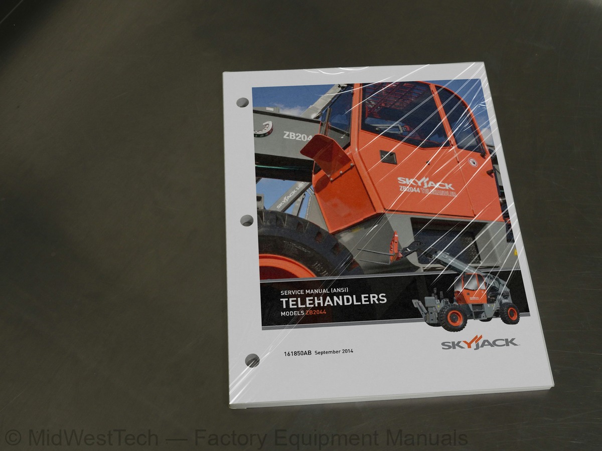
Skyjack ZB2044 Telehandler Service Manual
163 pages · Publication 161850AB
Added to your cart. View cart
- Models
- ZB2044
- Serial coverage
- ZB 2044 85800073 & Above
- Manual type
- Service Manual
- Pages
- 163
- Publication
- 161850AB
- Condition
- Brand new
What's inside
From the manual's own table of contents: 5 sections, 200 entries. See sample pages (PDF, 522 KB)
Section 1: Scheduled Maintenance26 topics
- Operator’s Responsibility for Maintenance
- Telehandler Definition
- Purpose of Equipment
- Use of Equipment
- Manual
- Operator
- Service Policy and Warranty
- Optional Accessories
- Scope of this Manual
- Operator Safety Reminders
- Electrocution Hazard
- Safety Precautions
- Maintenance and Inspection Schedule
- Owner’s Annual Inspection Record
- Replacement Parts
- Maintenance and Service Safety Tips
- Hydraulic System & Component Maintenance and Repair
- Maintenance Hints
- Service and Maintenance
- About this Section
- Service Bulletins
- Maintenance and Inspection
- Maintenance Instructions
- Maintenance and Inspection Checklist
- Scheduled Maintenance Inspections
- Function Tests
Section 2: Maintenance Tables and Diagrams5 topics
- Telehandler Specifications and Features
- Recommended Fluids/Lubrication
- Axles Torque Specifications
- Tire Specifications
- Pressure Settings
Section 3: System Component Identification and Schematics46 topics
- Charts
- Hydraulic Symbol Chart
- Electrical Symbol Chart
- Harnesses Color Codes
- Diagrams and Schematics
- Hydraulic Schematic Parts List
- Electrical Component Parts List
- Priority Valve and Port Identifications
- Steering Valve and Port Identifications
- Diverter Valve and Port Identifications
- Parking Brake Valve and Port Identifications
- Brake Charge Valve and Port Identifications
- Frame Level and Axle Lock Valves and Port Identifications
- Cross-Over Relief Valve and Port Identifications
- Dual Charge Brake Pedal and Port Identifications
- Orbital Steering Motor and Port Identifications
- Main Valve and Main Ports Identifications
- Hydraulic Cylinders Identification
- Hydraulic Manifolds Location
- Instrument Panel Wiring Diagram (Base Model)
- 3.19a Main Wiring Harness - Tier 4i
- 3.19b Main Wiring Harness - Tier 3
- 3.20a Engine Harness (QSB4.5) - Tier 4i
- 3.20b Engine Harness (QSB4.5) - Tier 3
- Transmission T32000 Harness
- Frame Level Harness
- Axle Lock Harness
- Diverter Valve Harness, 2-Way
- Parking Brake Harness
- Steering Harness
- Horn, Fuel & Brake Pressure Switch Harness
- Joystick with Horizontal Rocker Switch
- Three-Speed Shifter
- Joystick, Two-Axis with Microswitch
- Power Module - Enclosed Cab Harnesses
- Power Module - Open Cab Harnesses
- Lighting Harness
- Wiper Harness
- Grappler Harness
- Outrigger Raise/Lower Harness
- Mine Spec. - Brakes Harness
- Mine Spec. - Pressure Switches Harness
- Mine Spec. - Steering Accumulator Harness
- Hydraulic Schematic
- 3.41a Master Wiring Diagram - Tier 4i
- 3.41b Master Wiring Diagram - Tier 3
Section 4: Troubleshooting Information55 topics
- Introduction
- Electrical System - Tier 4i
- 4.1-1 All Controls Inoperative (No Crank)
- 4.1-2 Engine Cranks but will not start
- 4.1-3 Can Bus Failure, no data/display on Murphy Powerview
- 4.1-4 No Throttle
- Electrical System - Tier 3
- 4.2-1 All Controls Inoperative (No Crank)
- 4.2-2 Engine Cranks but will not start
- 4.2-3 Can Bus Failure, no data/display on Murphy Powerview
- 4.2-4 No Throttle
- Electrical System - Common
- 4.3-1 No Drive (park brake releases)
- 4.3-2 No Forward Drive
- 4.3-3 No reverse drive
- 4.3-4 3rd speed range only
- 4.3-5 No 1st speed range
- 4.3-6 No Drive (park brake does not release)
- 4.3-7 Alternator not charging
- 4.3-8 Front steer mode only
- 4.3-9 No round steer mode
- 4.3-10 No crab steer mode
- 4.3-11 No carriage tilt function
- 4.3-12 No outrigger function
- 4.3-13 No right outrigger lower function
- 4.3-14 No right outrigger raise function
- 4.3-15 No left outrigger lower function
- 4.3-16 No left outrigger raise function
- 4.3-17 Rear axle locked, Front frame level in slow mode, brakes do not lock axle out, Axle lock light on, all boom angle
- 4.3-18 Rear axle and front frame level in slow mode, brake application locks out both axles, axle lock light on, all boo
- 4.3-19 Rear axle locked and front frame level operates normally, brake application locks out frame level, axle lock ligh
- 4.3-20 Rear axle locked, front frame level operates normally, axle lock light off, below 45 degrees
- 4.3-21 Rear axle lock works normally, front frame level in slow mode, axle lock, light off, below 45 degrees
- 4.3-22 Front frame level does not lock out with brake application above 45 degrees
- Hydraulic System
- 4.4-1 All controls inoperative
- 4.4-2 All Boom Functions Inoperative
- 4.4-3 No Boom Raise
- 4.4-4 No Boom Lower
- 4.4-5 No Boom Extend
- 4.4-6 No Boom Retract
- 4.4-7 No Carriage Tilt Back
- 4.4-8 No Carriage Tilt Forward
- 4.4-9 No Frame Level Right
- 4.4-10 No Frame Level Left
- 4.4-11 No Auxiliary/Optional Hydraulic Control
- 4.4-12 No Right Outrigger Lower
- 4.4-13 No Right Outrigger Raise
- 4.4-14 No Left Outrigger Lower
- 4.4-15 No Left Outrigger Raise
- 4.4-16 Brake System Charging Constantly or Too Frequently
- 4.4-17 Hard or No Steering
- 4.4-18 Wheels go out of Synch. When in 4 wheel steer mode
- 4.4-19 Park Brake will not Release
- 4.4-20 Park Brake will not Engage
Section 5: Procedures63 topics
- General
- Safety and Workmanship
- Engine and Transmission
- 5.1-1 Engine and Components
- 5.1-2 Fault Codes for Quantum Engines
- 5.1-3 PowerView General Information
- Display Parameters
- Faceplate Features
- Keypad Functions
- PowerView Menus (First Time Start Up)
- Error Messages - T4i
- Error Messages - T3
- 5.1-4 Replace Engine Oil and Filter
- 5.1-5 Check Engine Air Filter
- 5.1-6 Replace Fuel Filter
- 5.1-7 Check Fan Drive Belt
- 5.1-8 Check Transmission Filter Breather
- 5.1-9 Change Transmission Fluid and Filter
- 5.2-1 Check Hydraulic Oil
- 5.2-2 Change Hydraulic Tank Filter
- 5.2-3 Change Hydraulic Oil
- 5.2-4 Bleeding Hydraulic Circuits
- Bleed Carriage Tilt Circuit
- Bleed Boom Extend/Retract Circuit
- Bleed Boom Raise/Lower Circuit
- Bleed Frame Level Circuit
- Bleed Auxiliary/Optional Circuits
- Bleed Outriggers Circuit
- Bleed Brake Circuit
- Pressure Adjustment Procedures
- 5.3-1 Piston Pump Pressure
- 5.3-2 Port Relief Pressure
- 5.3-3 Priority Valve Relief Pressure
- 5.3-4 Pilot Pressure
- 5.3-5 Check Brake Accumulators
- 5.3-6 Charging Brake Accumulators
- 5.3-7 Charging Rear Axle Lock System
- Boom
- 5.4-1 Boom Hose Replacement
- 5.4-2 Boom Chain Replacement and Adjustment
- Extend Chain
- Retract Chain
- Chain Adjustment
- 5.4-3 Check Slide Pads
- 5.4-4 Replacing and Shimming Slide Pads
- Axles
- 5.5-1 Change Oil in Axles
- 5.5-2 Check Oil Level in Torque Hub
- Grease Points
- 5.6-1 Frame Grease Points
- 5.6-2 Boom Grease Points
- 5.6-3 Drive Axle Grease Points
- 5.6-4 Drive Shaft Grease Points
- Tires
- 5.7-1 Check Lug Nut Torque
- Coolant Draining Procedure
- 5.8-1 Radiator Fill Maintenance
- Positive Air Shutoff Rev Limiter Testing
- 5.9-1 Setting RPM Upper Limit
- Set #1. Variable Throttle
- Set #2. Optional Switch To Ground- Work Or Pump Mode
- Set #3. Constant Throttle (30% over setting)- I.e. Welders, Generators, Compressors
- Testing Your Settings
Inside this manual
Real pages from this service manual (163 pages). Open the sample pages (PDF, 521 KB)

- Specifications, page 39: Section 2 - Maintenance Tables and Diagrams
- Diagram, page 77: 3.24 Diverter Valve Harness, 2-Way
- Troubleshooting, page 127: Active Fault Codes
- Color page, page 14: Zoom Boom Telehandler Series
- Color page, page 43: Zoom Boom Telehandler Series
- Foldout diagram (color), page 67: Zoom Boom Telehandler Series
Other manuals for this machine
Save 10% on 2 manuals, 15% on 3 or more. Other manuals for the ZB2044 are listed below. Editions cover different serial number ranges: check the serial coverage and tick only the ones that match your machine.
Added to your cart. View cart
This is a service manual
Here's how it compares to the other manual types.
Service manual
Factory repair procedures and technical information such as specifications, troubleshooting, and wiring and hydraulic diagrams, for the models and systems the manual covers. See What's inside for its topics.
Operator's manual
Safe operation, controls, maintenance schedules, lubrication points, inspections, and basic checks. Repair procedures are in the service manual.
Parts manual
Illustrated diagrams with factory part numbers for identifying components and ordering parts. Repair procedures are in the service manual.
Engine service manuals are sometimes sold separately, since certain machine models were offered with more than one engine option.
What it's used for
Factory manual for in-house farm and construction shop use. Straightforward, complete, and easy to follow. It contains the OEM information dealership service departments and parts counters use to diagnose problems, identify components, and perform maintenance or repairs correctly.
Service shops and owner/operators who repair their own equipment
Identifying correct parts and seeing how assemblies come apart and go back together
Keeping equipment running with less downtime
Factory manual, 163 pages
Quantity one is the manual described above.
Fast free USA shipping
Ships in 1 business day.
60-day returns
Free if the mistake is ours. A manual ordered in error must come back unopened in its shrink-wrap; you pay return shipping and a 20% restocking fee applies. Return policy
Other editions and similar models
Questions about model, serial number, engine coverage or contents? Contact us before purchasing and we'll help confirm it's the right manual. Please verify the manual type, machine model, serial number range and engine coverage before purchasing: manuals ordered in error carry a 20% restocking fee (return policy).