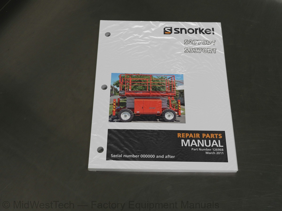
Snorkel S2770RT, S3370RT Scissor Lift Repair Parts Manual
95 pages · Publication 12696B
Added to your cart. View cart
What's inside
From the manual's own table of contents: 11 sections, 143 entries. See sample pages (PDF, 532 KB)
General Specifications4 topics
- General Specifications SR3370 3
- General Specifications SR2770 4
- Engine Data 5
- Engine Oil Charts 5
Maintenance Information46 topics
- About this Manual: 7
- Manual Organization 7
- General Specifications 7
- Maintenance 7
- Auto level system 7
- Repair parts and drawings 7
- Hydraulics 7
- Electrical 7
- Options 7
- Parts index - Page locator 7
- Maintenance and Schematics 7
- Maintenance information 7
- Maintenance schedules 8
- Daily Maintenance 9
- Pre-operational inspection 9
- Hydraulic Hose Age 9
- Day or 150 Hour Maintenance(Trained Service Technician) 10
- Yearly or 500 Hour Maintenance(Trained Service Technician) 10
- Lubricants 11
- Pressure gun application 11
- Lubrication 11
- King pins (Item 1) 11
- Tie rods (Item 2) 11
- Steer cylinder end (Item 3) 11
- Wheel bearingsDrive wheels (Item 4) 11
- Engines (Item 5) 12
- Hydraulic oil reservoir (Item 6) 12
- Return filter (Item 7) 12
- Door hinges and latches (Item 8) 12
- Slide pads (Item 9) 12
- Scissor arm bearings (Item 10) 12
- Batteries (Item 11) 12
- Preventive inspection maintenance90 day or 150 hour checklist 14
- Torque chart 16
- Servicing STC Fittings 17
- Disconnection 17
- Inspection 17
- Installation and connection 17
- Seal replacement instructions 18
- Auto Level System Troubleshooting 19
- Test procedures 19
- Using the EZcal 19
- EZcal auto level calibration procedure 20
- To order service or repair parts 22
- ANSI and OSHA compliance 22
- Manuals 22
Section 1. - Repair Parts31 topics
- Chassis assembly SR3370 1-2
- Chassis assembly drawing SR3370 1-3
- Chassis assembly drawing SR2770 1-4
- Chassis assembly SR2770 1-5
- Steer axle assembly 1-6
- Steer axle assembly drawing 1-7
- Drop axle assembly drawing 1-8
- Drop axle assembly 1-9
- Tray assembly, hydraulic and electrical 1-10
- Tray assembly, hydraulic and electricaldrawing 1-11
- Engine side tray assembly drawing 1-12
- Engine side tray assembly 1-13
- Cable operated emergency bleed down SR3370 1-14
- Cable operated emergency bleed down drawing SR3370 1-15
- Cable operated emergency bleed down drawing SR2770 1-16
- Cable operated emergency bleed down SR2770 1-17
- Scissor arm assembly SR3370 1-18
- Scissor arm assembly drawing SR3370 1-19
- Scissor arm assembly drawing SR2770 1-20
- Scissor arm assembly SR2770 1-21
- Outrigger Installation 1-22
- Outrigger Installation - drawing 1-23
- Platform assembly drawing 1-24
- Platform assembly 1-25
- Platform assembly 1-26
- Fuel tank assembly, diesel fuel 1-27
- Engine assembly, Kubota D905 1-28
- Engine assembly, Kubota D905 drawing 1-29
- Upper control box mounting assembly 1-31
- Placards and decals installation 1-32
- Placards and decals drawing 1-33
Section 2. - Hydraulics12 topics
- Hydraulic assembly 2-2
- wheel drive hydraulic schematic drawing 2-3
- Hose Part Numbers and Colour Codes 2-5
- Manifold assembly, main 2-6
- Manifold assembly, main drawing 2-7
- Manifold assembly, 4 wheel drive 2-8
- Manifold assembly, stabilisers 2-9
- Hydraulic oil tank assembly 2-10
- Hydraulic oil tank assembly drawing 2-11
- Steer axle cylinder 2-12
- Axle cylinder 2-13
- Main lift cylinder assembly 2-14
Section 3. - Electrical10 topics
- Electrical Schematic drawing - Auto Level 3-3
- Colour coded wiring circuit 3-5
- Ground control box assembly drawing 3-6
- Ground control box assembly 3-7
- Ground box 3-8
- Ground box drawing - sheet 1 3-9
- Ground box drawing - sheet 2 3-10
- Platform control box assembly 3-12
- Platform Control Box Assembly drawingSheet 1 3-13
- Platform Control Box Assembly drawingSheet 2 3-14
Section 4. - Options3 topics
- AC outlet at platform, 230 volt 4-2
- Flashing light installation 4-3
- Fuel gauge option 4-4
Parts index - Page locator26 topics
- Volt AC outlet at platform, 4-2
- AC outlet at platform, 230 volt AC, 4-2
- Decal and placards installation, 1-32
- Ground clearance, 2-3, 2-4
- Ground control box assembly, 3-7
- Insulation rating, 2-3, 2-4
- Joystick controller, 3-12
- Key switch, 3-8
- Maintenance, 0-7
- Maintenance schedules, 0-8
- Manual organisation
- See Maintenance information - page 3
- Manual Organization, 0-7
- Maximum rated axle capacity, 2-3, 2-4
- Nominal working height, 2-3, 2-4
- Overall length (with stabilizers), 2-3, 2-4
- Placards and decals installation, 1-32
- Platform control box assembly, 3-12
- Safe working load (main deck), 2-3, 2-4
- Safe working load (roll out deck), 2-3, 2-4
- Temperature sensor, 3-8
- Travelling height, 2-3, 2-4
- Turning radius (inner), 2-3, 2-4
- Turning radius (outer), 2-3, 2-4
- Warranty - Limited
- See inside front cover
Inside this manual
Real pages from this repair parts manual (95 pages). Open the sample pages (PDF, 531 KB)
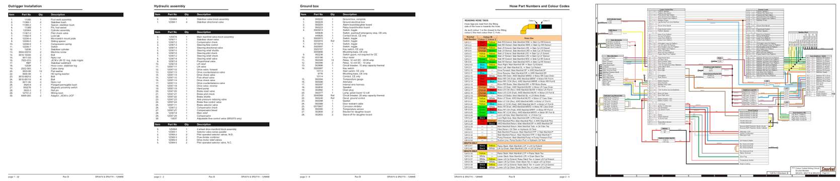
- Parts illustration, page 47: Outrigger Installation
- Parts illustration, page 61: Hydraulic assembly
- Parts illustration, page 81: Ground box
- Color page, page 64: Hose Part Numbers and Colour Codes
- Foldout diagram (color), page 78: RED/YELLOW
Other manuals for this machine
Save 10% on 2 manuals, 15% on 3 or more. Other manuals for the S2770RT, S3370RT are listed below. Editions cover different serial number ranges: check the serial coverage and tick only the ones that match your machine.
Added to your cart. View cart
This is a parts manual
Here's how it compares to the other manual types.
Service manual
Factory repair procedures and technical information such as specifications, troubleshooting, and wiring and hydraulic diagrams, for the models and systems the manual covers. See What's inside for its topics.
Operator's manual
Safe operation, controls, maintenance schedules, lubrication points, inspections, and basic checks. Repair procedures are in the service manual.
Parts manual
Illustrated diagrams with factory part numbers for identifying components and ordering parts. Repair procedures are in the service manual.
What it's used for
Factory manual for in-house farm and construction shop use. Straightforward, complete, and easy to follow. It contains the OEM information dealership service departments and parts counters use to diagnose problems, identify components, and perform maintenance or repairs correctly.
Service shops and owner/operators who repair their own equipment
Identifying correct parts and seeing how assemblies come apart and go back together
Keeping equipment running with less downtime
Factory manual, 95 pages
Quantity one is the manual described above.
Fast free USA shipping
Ships in 1 business day.
60-day returns
Free if the mistake is ours. A manual ordered in error must come back unopened in its shrink-wrap; you pay return shipping and a 20% restocking fee applies. Return policy
Other editions and similar models
Questions about model, serial number, engine coverage or contents? Contact us before purchasing and we'll help confirm it's the right manual. Please verify the manual type, machine model, serial number range and engine coverage before purchasing: manuals ordered in error carry a 20% restocking fee (return policy).