MidWestTechService, Parts and Operator's Manuals, in stock and ready to ship!
Fast free USA shippingShips in 1 business daySave 10% on 2 manuals, 15% on 3+

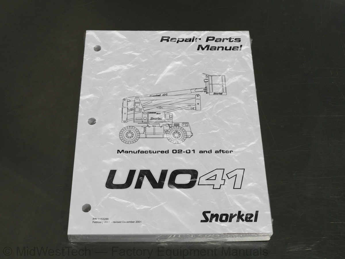
Snorkel UNO41 Articulating Boom Lift Repair Parts Manual

215 pages · Publication 0153286

$69.95
Fast free USA shippingShips in 1 business daySave 10% on 2 manuals, 15% on 3 or morePay by credit or debit card or with PayPal. No PayPal account needed.
Models
UNO41
Serial coverage
Manufactured February 2001 and after
Manual type
Repair Parts Manual
Pages
215
Publication
0153286
Condition
Brand new
Snorkel UNO41 Articulating Boom Lift Repair Parts Manual, publication 0153286

What's inside

From the manual's own table of contents: 193 sections, 312 entries. See sample pages (PDF, 472 KB)

Service and parts information4 topics
  • To order service or repair parts i
  • ANSI and OSHA compliance i
  • Manuals i
  • Parts order form ii
Section 1. - Repair parts25 topics
  • Chassis/turntable mounting 1-2
  • Drive 1-3
  • Steering 1-4
  • Swing drive mounting 1-7
  • Fuel tank 1-8
  • Hy drau lic oil res er voir mount ing 1-9
  • Booms mounting 1-10
  • Up per boom and hose car rier 1-12
  • Up per boom 1-15
  • Hose carrier 1-16
  • Platform, gravity gate 1-20
  • Platform, swinging gate 1-23
  • Platform rotation gear box, Hub City 1-24
  • Chassis cowling 1-26
  • Turntable cowling 1-28
  • Engine mounting, Ford gasoline 1-30
  • Engine, Ford gasoline 1-33
  • Engine mounting, Kubota diesel 1-36
  • Engine, Kubota diesel 1-39
  • Air cleaner 1-41
  • Placards and decals 1-42
  • Gear hub, drive - Auburn 1-44
  • Gear hub, steer - Auburn 1-46
  • Swing drive, Per fec tion 1-48
  • Tires and wheels 1-50
Section 2. - Hydraulics51 topics
  • Chassis hydraulic equipment 2-2
  • Chassis hydraulic hoses 2-5
  • Turntable hydraulic equipment 2-6
  • Turn ta ble hy drau lic hoses 2-7
  • Booms hydraulic equipment 2-8
  • Package valve, Vickers 2-11
  • Control valve package, Vickers 2-12
  • Add-on valve, Vickers 2-14
  • Control valve, drive 2-15
  • Drive control valve 2-16
  • Transmission valve 2-18
  • AC generator valve 2-20
  • Accumulator, chassis 2-21
  • Accumulator, turntable 2-22
  • Check valve 2-23
  • Lower boom lift cylinder 2-24
  • Cyl in der, lower boom lift - Rosenboom 2-25
  • Cyl in der, lower boom lift - Texas 2-26
  • Middle boom lift cylinder before 5-09-2001 2-27
  • Middle boom lift cylinder after 5-09-2001 2-28
  • Upper boom lift cylinder 2-29
  • Cylinder, boom lift - GBI 2-30
  • Cyl in der, boom lift - Green 2-31
  • Cyl in der, boom lift - Seabee 2-32
  • Cyl in der, boom lift - Rosenboom 2-33
  • Cylinder, extension - GBI 2-34
  • Cyl in der, ex ten sion - Rosenboom 2-35
  • Master level cylinder 2-36
  • Cyl in der, master level - Green 2-37
  • Cylinder, master level - Prince 2-38
  • Cyl in der, master level - Rosenboom 2-39
  • Slave level cylinder 2-40
  • Cylinder, slave level - GBI 2-41
  • Cylinder, slave level - Prince 2-42
  • Cyl in der, slave level - Texas 2-43
  • Cyl in der, steering - Texas 2-44
  • Dual counterbalance valve, Fluid Tech 2-45
  • Emergency power pump 2-46
  • Flow divider, Fluid Tech 2-47
  • Gear flow divider 2-48
  • High-low speed valve 2-49
  • Hydraulic motor and brake 2-50
  • Hydraulic oil reservoir 2-51
  • Hy drau lic drive mo tor, steer ing 2-52
  • Hy drau lic drive mo tor, drive 2-54
  • Hydraulic oil return filter 2-56
  • Hydraulic pump and fittings 2-57
  • Sense line dump valve 2-58
  • Solenoid valve, high-low shift 2-59
  • Transmission valve package, Fluid Tech 2-60
  • Pres sure switch 2-61
Sec tion 3. - Electrical20 topics
  • Chassis electrical, Ford 3-2
  • Chassis electrical, Kubota 3-5
  • Turntable electrical, Ford 3-6
  • Turntable electrical, Kubota 3-9
  • Platform electrical 3-10
  • Wiring box, Ford 3-12
  • Wiring box, Kubota 3-15
  • Wiring box panel, Ford 3-16
  • Wiring box panel, Kubota 3-19
  • Upper control box, Ford 3-20
  • Upper control box, Kubota 3-24
  • Engine gauge panel, Ford 3-27
  • Engine gauge panel, Kubota 3-32
  • Platform foot switch 3-35
  • Boom switch, Ford 3-36
  • Boom switch, Kubota 3-37
  • Steer switch, left hand 3-38
  • Steer switch, right hand 3-39
  • Power to Platform, 125 volt 3-40
  • Controller, drive 3-42
Section 4. - Factory installed options17 topics
  • Hydraulic AC generator 4-2
  • AC generator 4-7
  • Airline to platform 4-8
  • Driving lights and tail lights 4-11
  • Dual fuel, Ford 4-12
  • Dual fuel engine, Ford 4-15
  • LP fuel only, Ford 4-16
  • LP fuel engine, Ford 4-19
  • Engine block heater 4-20
  • Lanyard anchor, platform floor 4-21
  • Motion alarm 4-22
  • Operator horn 4-23
  • Tool tray 4-24
  • Tow package 4-26
  • Warning lights 4-28
  • Work lights 4-31
  • Up per con trol box cover 4-32
Ac cu mu la tor, turn ta ble, 2-22
Ad just ment bar, 1-34
Ad just ment bolt, 1-7
Air cleaner ser vice in di ca tor, 1-33, 1-39
Air in take gas ket, 1-34
Air in take hose, 1-34
Alarm, drive mo tion, 4-22
An gle, air hose, 4-8
Bat tery hold down bolt, 3-6, 3-9
Bracket, chas sis, 4-26
Ca ble guide, 4 roller, 4-8
Ca ble, 110 volt power to plat form, 3-40
Car tridge valve, 3-way , 2-60
Car tridge valve, 3-way in let, 2-12
Check valve car tridge, 2-12
Clevis pin, 1-39
Con trol ler, drive, 3-42
Cover, elec tri cal out let, 3-40
Cyl in der, steer ing, 1-4
Show all 193 sections
De cal set, non-pro por tional con trol valve, 2-11
De cal, 4 inch stripe, 1-42
De cal, at tach fall re straint, 1-42, 4-21
De cal, cau tion gov er nor dam age, 1-42
De cal, dan ger cyl in der fail ure, 1-42
De cal, dan ger de scend ing boom, 1-42
De cal, dan ger elec tri cal haz ard, 1-42
De cal, dan ger ro tat ing en gine parts, 1-42
De cal, dan ger you must not op er ate, 1-42
De cal, die sel fuel, 1-42
De cal, di rec tional ar rows, 1-42
De cal, di rec tional ar rows for ward/re verse, 1-42
De cal, do not use ether, 1-42
De cal, dual fuel in struc tions, 4-12, 4-16
De cal, emer gency man ual bleed down, 1-42
De cal, en gine block heater, 4-20
De cal, float valve, 4-26
De cal, gas o line fuel, 1-42
De cal, gauge panel, 3-27
De cal, hy drau lic oil, 1-42
De cal, lift and pull, 1-42
De cal, lube rec om men da tions, 1-42
De cal, lug nut torque, 1-42
De cal, OmniQuip logo, 1-42
De cal, ro tate while greas ing, 1-2
De cal, Snor kel brand logo, 1-42
De cal, tow ing in struc tions, 4-26
Di ode stand off, 3-16
Doc u ment tube, 1-42
Door latch, 1-23
Drag link stor age cra dle, 4-26
Drive wheel, 1-50
Dual coun ter bal ance valve, 2-16, 2-45
Dual fuel en gine, Ford, 4-15
Dual fuel kit, liq uid with drawal, 4-15, 4-19
Elec tri cal haz ard1 topic
  • See in side front cover
Elec tri cal out let box, 3-40
Elec tri cal out let, GFCI - 20 amp ca pac ity, 3-40
Emer gency power mo tor/pump, 2-46
Emer gency power pump, 2-2, 2-46
En gine adapter, Ford en gine, 1-39
En gine block heater, 4-20
En gine gauge panel, Ford, 3-2, 3-27
En gine gauge panel, Kubota, 3-5, 3-32
En gine, Ford VSG-413 gas o line, 1-33
Ex haust adapter, 1-34
Ex haust tube, 1-40
Fil ter, sump strainer, 2-51
Float valve mount bracket, 4-26
Floating tur ret, lower, 1-10
Floating tur ret, up per, 1-10
Flo ta tion drive wheel, 1-50
Fly wheel hous ing cou pling kit, 1-33
Fuel gauge, 1-8
Fuel hose as sem bly, 1-36
Fuel primer bulb, 1-36
Fuel tank, 20 gal lon ca pac ity, 1-8
Fuse holder, in-line, 4-31
Gas o line fuel shut-off valve, 4-15
Grav ity gate, 1-20
Hair pin clip pin, 4-26
Head light, halo gen flood, 4-11
Hose car rier, 1-12
Hy drau lic mo tor and brake, 1-3, 2-50
Hy drau lic oil fil ter, 2-56
Hy drau lic oil res er voir, 1-9, 2-51
Hy drau lic oil re turn fil ter, 2-2, 2-56
Hy drau lic pump, 2-57
Knob, gate hinge pin, 1-23
Latch stop, 1-23
Light, halo gen with clamp bracket, 4-31
Light, in can des cent with clamp bracket, 4-31
Light, turn sig nal, 4-11
Liq uid level gauge with ther mom e ter, 2-51
Lower boom, 1-10
Lower boom lift cyl in der, 1-10, 2-24
LP gas cyl in der, liq uid with drawal, 4-12, 4-16
Mid dle boom, 1-10
Mid dle boom lift cyl in der, 1-10
Mid dle boom lift cyl in der, 2-27, 2-28
Mo tor mount, left front, 1-39
Mo tor mount, left rear, 1-39
Mo tor mount, right front, 1-39
Mo tor mount, right rear, 1-39
Mount plate, over flow res er voir, 1-30
Mount, left hand, 1-33
Mount, mas ter level cyl in der, 2-36
Mount, right hand, 1-33
Mount ing band, air cleaner, 1-33, 1-39
Mount ing bracket, air cleaner, 1-33
Mount ing bracket, wir ing box, 3-6, 3-9
Pack age valve, Vickers, 2-11
Pad stop bar, 1-15
Pin, drag link, 4-26
Pin, gate hinge, 1-23
Pin, mas ter level cyl in der to mount plate, 2-36
Plac ard, AC gen er a tor, 4-2
Plac ard, ANSI stan dard, 1-42
Plac ard, bat tery dis con nect switch, 3-6, 3-9
Plac ard, cau tion liq uid with drawal, 4-12, 4-16
Plac ard, cau tion op er at ing in struc tions, 1-42
Plac ard, cau tion se rial num ber, 1-42
Plac ard, choke, 1-42
Plac ard, cir cuit breaker, 3-28, 3-32
Plac ard, con trol box front, 3-20, 3-24
Plac ard, dan ger foam filled tires, 1-42
Plac ard, dual fuel switch, 4-12
Plac ard, emer gency bleed down valve, 1-42
Plac ard, en gine pro tec tion sys tem, 3-27
Plac ard, en gine rpm, 1-42
Plac ard, horn, 4-23
Plac ard, light switch, 4-11
Plac ard, lug nut torque, 1-42
Plac ard, plat form ca pac ity 500 pounds, 1-42
Plac ard, plat form iden ti fi ca tion, 1-42
Plac ard, pre heat 10 sec onds, 1-42
Plac ard, tire pres sure, 1-42
Plas tic track link, 1-16
Plat form ro ta tion gear box, 1-20, 1-24
Power wire, 1-16
Ra di a tor mount ing bracket, 1-30, 1-36
Re cord pouch, 1-42
Roller spacer, alu mi num grav ity gate, 1-20
Roller, alu mi num grav ity gate, 1-20
Ro ta tion bear ing, 1-2
Ro ta tor stop, 4-26
Rub ber bumper, 1-28
Shut tle valve car tridge, 2-12
Slave level cyl in der mount, 1-15
Slide pad mount, 1-15
Slide pad mount ing bar, 1-12
Slide pad shim, 1-15
Slide pad spacer, 1-15
Slide pad track, 1-12
So le noid valve, 2-58
So le noid valve, high-low shift, 2-49, 2-59
Spacer, tie rod mount ing, 1-4
Spring, tor sion, 1-23
Steer yoke, left hand, 1-4
Steer yoke, right hand, 1-4
Steering float valve, 4-26
Swing drive mo tor, 1-7
Swinging gate, alu mi num plat form, 1-23
Switch, bat tery dis con nect, 3-6, 3-9
Switch, pres sure, 2-61
Tire and wheel, flo ta tion, 1-50
Tire and wheel, left hand drive, 1-50
Tire and wheel, right hand drive, 1-50
Trans mis sion valve pack age, 2-60
Tur ret hose guard, 2-8
Up per boom and hose car rier, 1-12
Up per con trol box hand rail, 1-20, 1-23
Warn ing light, 4-28
War ranty1 topic
  • See in side back cover
Wire har ness, AC gen er a tor, 4-2
Wire har ness, al ter na tor con nec tor, 3-2
Wire har ness, boom switch, 3-36, 3-37
Wire har ness, chas sis drive, 3-2, 3-5
Wire har ness, Ford en gine, 3-2, 3-27
Wire har ness, high-low speed, 3-2, 3-5
Wire har ness, Kubota en gine, 3-5, 3-32
Wire har ness, plat form foot switch, 3-35
Wire har ness, steer switch, 3-38, 3-39
Wire har ness, turn ta ble, 3-6, 3-9
Wire har ness, up per con trol box in ter nal, 3-20, 3-24
Wire har ness, wir ing box in ter nal, 3-12, 3-15
Wiring box panel, Ford, 3-16
Wiring box panel, Kubota, 3-19
Maintenance

Inside this manual

Real pages from this repair parts manual (215 pages). Open the sample pages (PDF, 473 KB)
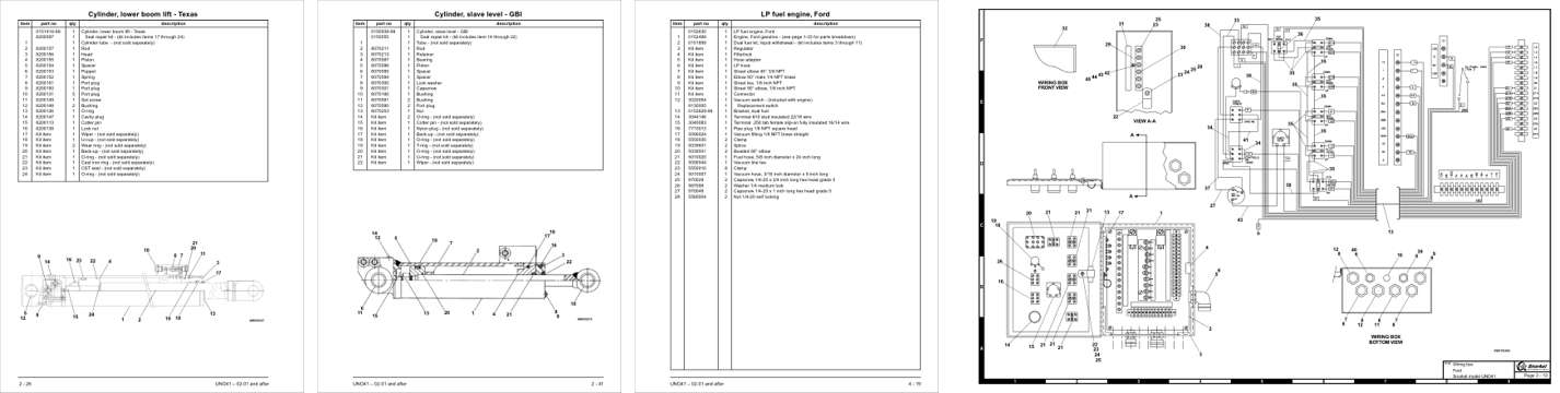
Sample pages from the Snorkel UNO41 Articulating Boom Lift Repair Parts Manual: Parts illustration, Parts illustration, Parts illustration, Foldout diagram
  • Parts illustration, page 83: Cylinder, lower boom lift - Texas
  • Parts illustration, page 98: Cylinder, slave level - GBI
  • Parts illustration, page 182: LP fuel engine, Ford
  • Foldout diagram, page 132: Wiring box

This is a parts manual

Here's how it compares to the other manual types.

Service manual

Factory repair procedures and technical information such as specifications, troubleshooting, and wiring and hydraulic diagrams, for the models and systems the manual covers. See What's inside for its topics.

Operator's manual

Safe operation, controls, maintenance schedules, lubrication points, inspections, and basic checks. Repair procedures are in the service manual.

This manual

Parts manual

Illustrated diagrams with factory part numbers for identifying components and ordering parts. Repair procedures are in the service manual.

What it's used for

Factory manual for in-house farm and construction shop use. Straightforward, complete, and easy to follow. It contains the OEM information dealership service departments and parts counters use to diagnose problems, identify components, and perform maintenance or repairs correctly.

Service shops and owner/operators who repair their own equipment

Identifying correct parts and seeing how assemblies come apart and go back together

Keeping equipment running with less downtime

Factory manual, 215 pages

Quantity one is the manual described above.

Fast free USA shipping

Ships in 1 business day.

60-day returns

Free if the mistake is ours. A manual ordered in error must come back unopened in its shrink-wrap; you pay return shipping and a 20% restocking fee applies. Return policy

Other editions and similar models

Questions about model, serial number, engine coverage or contents? Contact us before purchasing and we'll help confirm it's the right manual. Please verify the manual type, machine model, serial number range and engine coverage before purchasing: manuals ordered in error carry a 20% restocking fee (return policy).