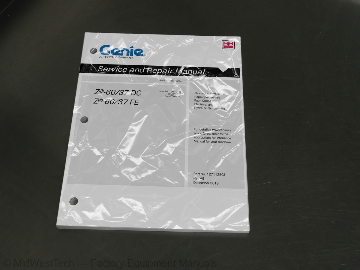
Terex Genie Z-60/37 DC, Z-60/37 FE Articulated Boom Lift Service Manual
125 pages · Publication 1271125
Added to your cart. View cart
- Models
- Genie Z-60/37 DC, Z-60/37 FE
- Serial coverage
- from Z6016N-101 to Z6016N-599, from Z60N-600
- Manual type
- Service Manual
- Pages
- 125
- Publication
- 1271125
- Condition
- Brand new
What's inside
From the manual's own table of contents: 9 sections, 98 entries. See sample pages (PDF, 596 KB)
Introduction Introduction3 topics
- Important Information
- Find a Manual for this Model
- Serial Number Legend
Section 1 Safety Rules1 topic
- General Safety Rules
Section 2 Specifications10 topics
- Machine Specifications
- Performance Specifications
- Hydraulic Specification
- Hydraulic Component Specifications
- Manifold Component Specifications
- Kubota D1105 Engine Specifications
- Machine Torque Specifications
- Machine Component Weights
- Hydraulic Hose and Fitting Torque Specifications
- Torque Procedure
Section 3 Repair Procedures51 topics
- Introduction
- Cailbration Process Steps
- Platform Controls
- How to Adjust the Joystick Threshold Setting
- How to Adjust the Joystick Max-out Setting
- How to Adjust the Joystick Ramp Rate Setting
- How to Calibrate Booms Angle Sensors
- How to Clear the Fault History
- Platform Components
- Platform Leveling Slave Cylinder
- Platform Rotator
- Platform Overload System
- How to Reset Overload Recovery Message
- Jib Boom Components
- Jib Boom
- Jib Boom Lift Cylinder
- Primary Boom Components
- Cable Track
- How to Repair the Cable Track
- Primary Boom
- How to Disassemble the Primary Boom
- Primary Boom Lift Cylinder
- Primary Boom Extension Cylinder
- Platform Leveling Master Cylinder
- Secondary Boom Components
- Secondary Boom Lift Cylinder
- Engines
- RPM Adjustment
- How to Replace the Motor Tach Sensor
- Hydraulic Pumps
- Function Pump
- How to Check the Function Pump Calibration
- Manifolds
- Function Manifold Components
- Valve Adjustments - Function Manifold
- How to Adjust the Platform Level Up Relief Valve
- How to Adjust the Primary Boom Extend Relief Valve
- Jib Boom / Platform Rotate Manifold Components
- Turntable Rotation Manifold Components
- Oscillate Directional Valve Manifold Components
- How to Set Up the Oscillate Directional Valve
- How to Adjust the Oscillate Reducing Valve
- How to Test a Coil Diode
- Turntable Rotation Components
- Turntable Rotation Assembly
- How to Replace the Universal Tilt Sensor
- How to Calibrate the Universal Tilt Sensor
- Axle Components
- Oscillating Axle Cylinders
- How to Remove the Steer Cylinder
- How to Calibrate the Steer Angle Sensor
Section 4 Fault Codes3 topics
- Control System Fault Codes
- Fault Codes Ground Controls
- How to Retrieve Control System Fault Codes - Platform Controls
Section 5 Navigation Menus3 topics
- Faults Navigation Menu
- Options Navigation Menu
- Settings Navigation Menu
Section 6 Schematics18 topics
- Electrical Symbol Legend
- Hydraulic Symbols Legend
- Electrical Component and Wire Color Legends
- Kubota Engine Fuse and Relay Module
- 12V DC Charger Wiring (DC Option)
- AC Input Wiring (DC Option)
- CAN BUS Wiring Diagram - DC Models
- Limit Switch/Angle Sensor Legend
- Electrical Schematics – Options
- Wiring Diagram - Options
- Schematics - Options, 4WD, DC, and FE Models
- Power Cable Wiring Diagram
- Hydraulic Schematics
- Hydraulic Schematic - DC and FE Models
- Electrical Schematics
- Electrical Schematics, DC/FE Models
- Ground Control Box Terminal Strip Wiring Diagram
- Platform Control Box Wiring Diagram
Inside this manual
Real pages from this service manual (125 pages). Open the sample pages (PDF, 595 KB)
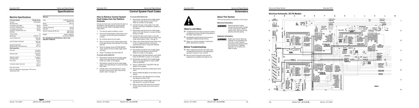
- Specifications, page 11: Specifications
- Troubleshooting, page 75: Control System Fault Codes
- Diagram, page 95: Schematics
- Foldout diagram, page 116: Service and Repair Manual
This is a service manual
Here's how it compares to the other manual types.
Service manual
Factory repair procedures and technical information such as specifications, troubleshooting, and wiring and hydraulic diagrams, for the models and systems the manual covers. See What's inside for its topics.
Operator's manual
Safe operation, controls, maintenance schedules, lubrication points, inspections, and basic checks. Repair procedures are in the service manual.
Parts manual
Illustrated diagrams with factory part numbers for identifying components and ordering parts. Repair procedures are in the service manual.
Engine service manuals are sometimes sold separately, since certain machine models were offered with more than one engine option.
What it's used for
Factory manual for in-house farm and construction shop use. Straightforward, complete, and easy to follow. It contains the OEM information dealership service departments and parts counters use to diagnose problems, identify components, and perform maintenance or repairs correctly.
Service shops and owner/operators who repair their own equipment
Identifying correct parts and seeing how assemblies come apart and go back together
Keeping equipment running with less downtime
Factory manual, 125 pages
Quantity one is the manual described above.
Fast free USA shipping
Ships in 1 business day.
60-day returns
Free if the mistake is ours. A manual ordered in error must come back unopened in its shrink-wrap; you pay return shipping and a 20% restocking fee applies. Return policy
Other editions and similar models
Questions about model, serial number, engine coverage or contents? Contact us before purchasing and we'll help confirm it's the right manual. Please verify the manual type, machine model, serial number range and engine coverage before purchasing: manuals ordered in error carry a 20% restocking fee (return policy).