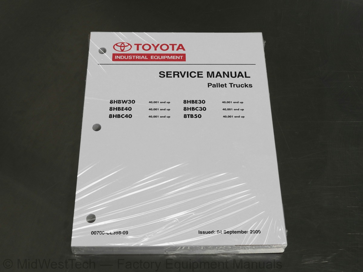
Toyota 8HBW30, 8HBE30, 8HBE40, 8HBC30, 8HBC40, 8TB50 Pallet Truck and Tow Tractor Service Manual
281 pages · Publication 00700-CL398-09
Added to your cart. View cart
What's inside
From the manual's own table of contents: 13 sections, 489 entries. See sample pages (PDF, 470 KB)
General1 topic
- Document Revision History
Section 1. How To Use This Manual4 topics
- Map of the Manual
- Manual Design
- Abbreviations & Symbols
- START Page
Section 2. Safety12 topics
- Definitions
- General Safety
- Battery Safety
- Jacking Safety
- Tractor Section
- Fork Section
- Tie-Down for Transport
- Figure 2-1. Tie-Down for Transport
- Towing
- Static Safety
- Figure 2-2. Anti-Static Kit (P/N 1-187-059) With Wrist Strap and Mat
- Welding Safety
Section 3. Systems Overview48 topics
- Introduction
- Truck Model Identification
- Figure 3-1. Model 8HBW30 Low Lift Walk-Behind
- Figure 3-2. Model 8HBE30/40 End Rider
- Figure 3-3. Model 8HBC30/40 Center Rider
- Figure 3-4. Model 8TB50 Tow Tractor
- Lift Truck Specifications
- Figure 3-5. Lift Truck Specification Plate - Models 8HBW, 8HBE, and 8HBC Pallet Trucks
- Figure 3-6. Lift Truck Specification Plate - Model 8TB50 Tow Tractor
- General System Data
- Figure 3-7. Model 8HBE30/40 (Long-John Forks Shown)
- Figure 3-8. Model 8HBE30/40 Control Handle
- Special Tools
- Service Key
- Figure 3-9. Service Key
- Operator Display and Programming
- Figure 3-10. Operator Display
- Special Truck Mode
- Hour Meter (H)
- Error Codes (E)
- Changing Truck Parameters (P)
- Service Input/Output Displays
- Figure 3-11. Service Key Connection Point
- Figure 3-12. Operator Display
- Digital Inputs/Outputs from Traction Amplifier and VM
- Toyota FlashWare
- Overview
- Requirements
- Installing FlashWare on PC
- Connecting PC to Truck
- Starting FlashWare
- Figure 3-13. Truck Opening Screen with Menu
- Configuration and Truck Setup Options
- Figure 3-14. Typical Truck Setup Screen
- Changing Truck Parameters
- Figure 3-15. Change Parameter
- Figure 3-16. Send Changes Button
- Software Management
- Figure 3-17. Truck Setup Screen Software Button
- Figure 3-18. Truck Software Window
- Erase Vehicle Manager
- Figure 3-19. Erase Vehicle Manager Software Screen
- Reset Defaults
- Diagnostics
- Error Log
- RE_Read Truck Settings
- SAVE Settings to File
- SEND Changes to Truck
Section 4. Planned Maintenance13 topics
- Maintenance Guidelines
- Initial 90 Day/250 Deadman Hours (HD) Maintenance
- Every 180 Days or 500 Deadman Hours
- Every 360 Days or 2000 Deadman Hours (HD)
- Contactor Tip Inspection
- Grease Fittings (All Models)
- Figure 4-1. Caster Grease Fittings
- Figure 4-2. Load Wheel Grease Fittings
- Grease Fittings (Trucks without Composite Bushings Only)
- Figure 4-3. Upper Bell Crank Grease Fittings (Between Tractor and Fork Section)
- Figure 4-4. Lower Bell Crank Grease Fittings-left side shown (Between Tractor and Fork Section)
- Figure 4-5. Lower Bell Crank Grease Fittings-left side shown (Between Tractor and Fork Section)
- Figure 4-6. Fork Grease Fittings (Top View)
Section 5. Troubleshooting33 topics
- How to Use This Section
- Troubleshooting Flowcharts
- TS1: START TROUBLESHOOTING
- Figure 5-1. TS1: START TROUBLESHOOTING
- GEN1: General Troubleshooting
- Figure 5-2. GEN1: General Troubleshooting
- END1: End of Troubleshooting Procedure
- Figure 5-3. END1: End of Troubleshooting Procedure
- Electrical Troubleshooting Guidelines
- Troubleshooting the CAN Bus
- Shorts to Frame Test
- Fuses
- Figure 5-4. Fuse Location
- Test/Inspection
- DC Electric Motors
- DC Motor Types
- Figure 5-5. Motor Circuits
- Inspection
- Service
- Open Circuit Motor Test
- Grounded Motor Test
- Short-Circuited Armature
- Short-Circuited Winding
- AC Electric Motors
- AC Motor Type
- Figure 5-6. AC Traction Motor circuit - Phase A
- Figure 5-7. AC Traction Motor circuit - Phase B
- Open Winding
- Shorted Winding
- Hydraulic Troubleshooting Guidelines
- Symptom Tables: Lift/Lower System
- Symptom Tables: Travel (Forward/Reverse) System
- Symptom Tables: Wiring System
Section 6. Messages and Codes8 topics
- List of Messages and Codes
- Traction Amplifier LED Diagnostics
- Figure 6-1. Traction Amplifier Status Indicator LED
- Traction Amplifier Flash Codes
- Caution and Error Codes
- Figure 6-2. Operator Display
- Caution Codes
- Error Codes
Section 7. Component Procedures295 topics
- List of Component Procedures by Truck System
- Component Locator Photos
- Figure 7-1. Inside Tractor, Rear View
- Figure 7-2. Inside Tractor, Right Side
- Figure 7-3. Inside Tractor, Left Side
- Control Handle - Model 8HBW30
- Figure 7-4. Model 8HBW30 Control Head Assembly - Exploded View
- Control Handle Disassembly
- Changing Horn Button/Switch [26, 27]
- Figure 7-5. Horn Button Removal
- Changing Lift/Lower Button [22]
- Figure 7-6. Lift/Lower Button Removal
- Changing Push Button [19]
- Figure 7-7. Push Button Removal
- Spring-Loaded Handle Design
- Removal
- Figure 7-8. Control Handle Base Cover Removal
- Figure 7-9. Control Handle Wire Harness
- Figure 7-10. Remove Jam Nut at Coast Link
- Figure 7-11. Return Spring Rod Removal
- Installation
- Return Spring Adjustment
- Figure 7-12. Return Spring Adjustment
- Fixed-Position Handle Design - Models 8HBC30/40 and 8TB50
- Removal
- Installation
- Control Handle Assemblies - Models 8HBE, 8HBC and 8TB50
- Figure 7-13. Control Handle and Head Assembly - Model 8HBE30/40
- Figure 7-14. Control Handle with Hand Brake - Model 8HBC30/40 and 8TB50 (Fixed Handle)
- Figure 7-15. Control Handle with Deadman Brake - Model 8HBC30/40 and 8TB50 (Spring-Loaded Handle)
- Figure 7-16. Control Head Assembly (Models 8HBE30/40, 8HBC30/40, and 8TB50) - Exploded View
- Control Head Removal
- Changing Horn Button/Switch [24]
- Figure 7-17. Horn Button Removal
- Changing Lift/Lower Switch Activator [14]
- Figure 7-18. Lift/Lower Button Removal
- Changing the Push Button [3]
- Figure 7-19. Push Button Removal
- Figure 7-20. Handle with Jog Option
- Changing the Jog Trigger Switch [44]
- Changing the Jog Trigger and Spring
- Drive Unit
- Removal
- Figure 7-21. Drive Unit Fill Plug
- Figure 7-22. Drive Unit Drain Plug
- Figure 7-23. Drive Unit Mounting (Traction Motor Removed)
- Steering Bearing
- Removal
- Figure 7-24. Drive Unit (Shown installed in Tractor Frame)
- Figure 7-25. Drive Unit Bottom View
- Figure 7-26. Drive Unit, Steering Bearing Removed
- Installation
- Figure 7-27. Main Case Cover, Six Hole-Type, Installed
- Figure 7-28. Gear Housing and Cover
- Gear Assembly
- Figure 7-29. Lower Drive Unit, Cross-Sectional View
- Checking the Gears
- Adjusting Tooth Pattern of Drive Unit
- Figure 7-30. Drive Unit Gear Tooth Pattern
- Installation
- Figure 7-31. Drive Unit Gauge and Shimming Locations
- Figure 7-32. Drive Unit Mounting Screw Torque Sequence
- Figure 7-33. Drive Unit Drain Plug
- Drive Housing Lubrication
- Drive Wheel
- Removal
- Figure 7-34. Drive Wheel and Tire
- Cushion Tire Replacement
- Figure 7-35. Cushion Tire Replacement
- Caster Adjustment
- Casters (without Springs)
- Caster Removal
- Figure 7-36. Removing Caster Wheel Assembly
- Wheel Replacement
- Figure 7-37. Caster Assembly, Disassembled
- Caster Assembly
- Figure 7-38. Caster Assembly, Assembled
- Caster Installation
- Figure 7-39. Securing Caster To Tractor
- Casters (Spring-Loaded)
- Removal
- Figure 7-40. Removing Spring-Loaded Caster
- Wheel Replacement
- Figure 7-41. Removing Tension Pin
- Figure 7-42. Removing Axle Shaft
- Figure 7-43. Removed Wheel and Shims
- Caster Disassembly
- Figure 7-44. Compressing Caster Springs
- Figure 7-45. Relieving Pivot Tension
- Figure 7-46. Removing Pivot Pin Retainer Screw
- Figure 7-47. Removing Pivot Pin
- Figure 7-48. Separated Caster
- Caster Assembly
- Figure 7-49. Removing Bolts from Springs
- Wheel Installation
- Figure 7-50. Installing New Wheel
- Figure 7-51. Installing Axle Shaft
- Figure 7-52. Installing Tension Pin
- Caster Installation
- Figure 7-53. Caster, Shims and Mounting Bolts
- Figure 7-54. Securing Caster To Tractor
- Brake
- Spring-Loaded Handle
- Figure 7-55. Brake Release Bolt Storage Location
- Removal
- Figure 7-56. Brake Release Bolts, Installed
- Figure 7-57. Brake Release Bolts, Installed
- Installation
- Checking the Gap
- Figure 7-58. Measuring Brake Gap
- Replacing the Rotor
- Battery
- With Battery Gates and Rollers (Optional)
- Battery Gates (Optional)
- Battery Rollers (Optional)
- Without Battery Gates and Rollers
- Battery Exterior Cleaning
- Figure 7-59. Battery Filler Plugs and Vent Holes
- Testing, Charging, and Maintenance
- Maintenance-Free Batteries
- Storage
- Power Cables
- Power Cable Repair
- Figure 7-60. Short Barrel Terminal
- Figure 7-61. Long Barrel Terminals
- Wiring Harness
- Terminology
- Inspection
- Repair
- Soldering Procedures
- AMP Water-Resistant Connectors
- Figure 7-62. AMP Water-Resistant Connector
- Pin Extraction
- Figure 7-63. AMP Pin Extraction
- Figure 7-64. Removing Wire
- Pin Insertion
- Figure 7-65. Wire Seal
- Figure 7-66. Wire Insertion
- Seals
- Figure 7-67. Sealing Plug
- Figure 7-68. Interface Seal
- Figure 7-69. Latching AMP Connector
- AMP Harness/Traction Amplifier Connector
- Connector Components
- Figure 7-70. JPT1 Connector Components
- Disassembly (Contact Removal)
- Figure 7-71. AMP Connector (JT1 or JL1)
- Contact Insertion
- Assembly
- Figure 7-72. Contact Insertion
- Figure 7-73. Wedge Lock Latches
- Figure 7-74. Wedge Lock Flush With Housing
- Testing
- Brake Potentiometer (VR1)
- Removal
- Figure 7-75. Pot Cover Screw Locations
- Figure 7-76. Brake Control Assembly - Exploded View
- Installation
- Lift-Limit Switch (SW8)
- Figure 7-77. Lift-Limit Switch
- Adjustment
- Grab Rail Switches - Model 8HBE30/40
- Removal
- Figure 7-78. Grab Rail Switch Removal, Left Side
- Figure 7-79. Grab Rail Switch Removal, Right Side
- Installation
- Hydraulic Solenoids
- Figure 7-80. Hydraulic Solenoids (typical unit)
- Jog Pick Solenoid - Model 8HBE30/40 Option
- Removal
- Figure 7-81. Jog Pick Solenoid Location
- Figure 7-82. Socket Head Cap Screws
- Figure 7-83. Removed Solenoid Mechanism
- Installation
- Figure 7-84. Install Ball Bearings
- Jog Pick Solenoid Switch/Spring
- Jog Pick Canister
- Figure 7-85. Canister Spacing
- Repair
- Figure 7-86. Special Compression Tool
- Figure 7-87. Cylinder Secured In Hydraulic Press
- Figure 7-88. Removing Snap Ring
- Figure 7-89. Jog Pick Canister Components
- Figure 7-90. Assembling Coast PRO Canister
- Traction Amplifier
- Figure 7-91. Traction Amplifier Location
- Removal
- Figure 7-92. Removing the Traction Amplifier
- Installation
- Programming
- Motors, General
- Terminal Nuts
- Figure 7-93. Traction Motor Terminal Connections
- Figure 7-94. Lift and Auxiliary Motor Terminal Nuts
- Traction Motor
- Removal
- Figure 7-95. Control Handle Base Cover Removal
- Figure 7-96. Control Handle Base Cover Removal
- Figure 7-97. Traction Motor Power Cables
- Figure 7-98. Traction Motor Removal
- Figure 7-99. Drive Unit Pinion Gear
- Installation
- Figure 7-100. Main Case Location
- Lift Motor
- General Data
- Removal
- Figure 7-101. Bolts Securing Motor To Adapter
- Figure 7-102. Separated Reservoir and Motor (typical)
- Installation
- Figure 7-103. Coupling Cavity
- Figure 7-104. Indexing Pin
- Hydraulic Components
- General Guidelines
- Figure 7-105. Hydraulic Unit (typical shown)
- Hydraulic Fluid
- Checking Hydraulic Fluid Level
- Hydraulic Unit
- Removal
- Figure 7-106. Hydraulic Unit (typical shown)
- Installation
- Hydraulic Reservoir
- Removal
- Figure 7-107. Adapter Cap Screws
- Figure 7-108. Removed Reservoir
- Installation
- Filter Screen and Suction Tube
- Removal
- Figure 7-109. Pump Housing Components
- Figure 7-110. Cleaning Filter Screen
- Installation
- Hydraulic Pump
- Removal
- Figure 7-111. Pump and Adapter Body
- Installation
- Figure 7-112. Pump Drive Coupling
- Figure 7-113. Installing Pump In Adapter
- Adjusting Hydraulic Pump Relief Valve Pressure
- Figure 7-114. Checking Relief Valve Pressure
- Checking Relief Valve Setting
- Alternate Method Using Rated Load on Pallets
- Hydraulic Ram
- Inspection
- Removal
- Figure 7-115. Removing Lower Bell Crank Pins
- Figure 7-116. Disconnecting Upper Clevis Brackets
- Figure 7-117. Hydraulic Ram Area, Forks Removed
- Figure 7-118. Hydraulic Line Connection
- Figure 7-119. Vent Hose Connections
- Installation
- Figure 7-120. Hydraulic Ram Removal/Installation
- Figure 7-121. Hydraulic Line Connection (installed)
- Hydraulic Cylinder Seals
- Disassembly
- Figure 7-122. Remove Outer Spiral Lock Ring
- Figure 7-123. Remove the Spacer
- Figure 7-124. Remove Head Lock Ring From Cylinder
- Figure 7-125. Rod and Head Assembly Out of Cylinder
- Figure 7-126. Remove the Piston Jam Nut
- Figure 7-127. Piston Rod Components
- Assembly
- Figure 7-128. Correct Piston Seal Orientation
- Figure 7-129. Securing Piston Jam Nut
- Figure 7-130. Installing the Head Lock Ring
- Figure 7-131. Installing the Outer Lock Ring
- Top Linkage Subassembly
- Removal
- Figure 7-132. Blocking Fork Section
- Figure 7-133. Removing Lower Bell Crank Pins
- Figure 7-134. Disconnecting Upper Clevis Brackets
- Figure 7-135. Hydraulic Ram Area, Forks Removed
- Installation
- Figure 7-136. Hydraulic Ram Area, Installation
- Pull Rod Subassembly
- Removal
- Figure 7-137. Blocking Fork Section
- Figure 7-138. Removing Lower Bell Crank Pins
- Figure 7-139. Eccentric Pin and Retaining Screw
- Figure 7-140. Machined Fork Trail Assembly
- Figure 7-141. Machined Fork Trail Assembly
- Installation
- Figure 7-142. Hydraulic Ram Removal/Installation
- Load Wheel Suspension - Model 8TB50
- Removal
- Figure 7-143. Model 8TB50 Load Wheel Suspension - Exploded View
- Installation
- Fork Height Adjustment
- Figure 7-144. Fork Height Adjustment at Lower Bell Crank
- Measurement
- Figure 7-145. Measure Fork Height at Load Wheel
- Figure 7-146. Measure Fork Height at Battery Compartment
- Adjustment
- Figure 7-147. Eccentric Pin Adjustment
- Figure 7-148. Eccentric Pin Height Reference
- Figure 7-149. Downstop adjustment
- Cold Storage Conditioning
Section 8. Theory of Operation42 topics
- Acceleration Rate
- Brake Lever Potentiometer (VR1) (Models with Fixed Position Handles)
- Brake (Deadman) Switch (Models with Spring-Loaded Handle)
- Figure 8-1. Brake (Deadman) Switch and Brake Actuation
- Continuity
- Controller Area Network (CAN)
- Current Limiting
- Deceleration (Neutral Braking)
- Emergency Reverse (Models 8HBW30 and 8HBE30 or 8HBE40)
- Fault Codes
- High Pedal Disable (HPD)
- Jog Speed
- Open Circuit
- Overvoltage Cutoff
- PIN-Key Code
- Pulse Width Modulation
- Ramp Shape
- Regenerative Braking
- Sequencing Delay
- Short Circuit or “Short
- Speed Limiting
- Static Return to Off (SRO)
- Thermal Cutback (Traction Amplifier)
- Throttle Map
- Truck Off Delay (Keypad only)
- Undervoltage Cutoff
- VM (Vehicle Manager)
- Traction System
- Vehicle Manager (VM)
- Traction Amplifier (TA)
- Battery Plugged In
- Key Switch ON and M1 Energized
- Travel Request, Tractor-First
- Travel Request, Forks-First
- Strip Curtain Bypass (Model 8HBE30/40 only)
- Emergency Reverse (Model 8HBW30 and 8HBE30/40)
- Jog Mode
- Jog Pick Mode
- Lift/Lower System
- Lift
- Lower
- Pinout Matrix
Section A. Appendix19 topics
- Lubrication Equivalency Chart
- Thread Adhesives, Sealants, and Lubricants
- Component Specific Service/Torque Chart
- Torque Chart - Standard (Ferrous)
- Torque Chart - Standard (Brass)
- Torque Chart - Metric
- Torque Chart - Thread-Forming Screws
- Decimal Equivalent Chart
- Standard/Metric Conversions
- List of Electrical Symbols
- Electrical Schematics
- Figure A-1. Model 8HBW30 Standard
- Figure A-2. Model 8HBE30/40 Standard
- Figure A-3. Model 8HBC30/40 Standard
- Figure A-4. Model 8TB50 Standard
- Figure A-5. Options
- Figure A-6. Component Legend
- Power Distribution Diagram
- Hydraulic Schematic
Class III repair manual updates 05-14-2010.pdf1 topic
- Blank Page.pdf
Inside this manual
Real pages from this service manual (281 pages). Open the sample pages (PDF, 468 KB)

- Troubleshooting, page 74: Section 5. Troubleshooting
- Specifications, page 254: Section A. Appendix
- Diagram, page 266: Section A. Appendix
- Color page, page 133: Section 7. Component Procedures
- Color page, page 194: Toyota Pallet Truck Service Manual
- Foldout diagram, page 270: 00700-CL398-09, Issued: 04 Sep 2009
Other manuals for this machine
Save 10% on 2 manuals, 15% on 3 or more. Other manuals for the 8HBW30, 8HBE30, 8HBE40, 8HBC30, 8HBC40, 8TB50 are listed below. Editions cover different serial number ranges: check the serial coverage and tick only the ones that match your machine.
Added to your cart. View cart
This is a service manual
Here's how it compares to the other manual types.
Service manual
Factory repair procedures and technical information such as specifications, troubleshooting, and wiring and hydraulic diagrams, for the models and systems the manual covers. See What's inside for its topics.
Operator's manual
Safe operation, controls, maintenance schedules, lubrication points, inspections, and basic checks. Repair procedures are in the service manual.
Parts manual
Illustrated diagrams with factory part numbers for identifying components and ordering parts. Repair procedures are in the service manual.
Engine service manuals are sometimes sold separately, since certain machine models were offered with more than one engine option.
What it's used for
Factory manual for in-house farm and construction shop use. Straightforward, complete, and easy to follow. It contains the OEM information dealership service departments and parts counters use to diagnose problems, identify components, and perform maintenance or repairs correctly.
Service shops and owner/operators who repair their own equipment
Identifying correct parts and seeing how assemblies come apart and go back together
Keeping equipment running with less downtime
Factory manual, 281 pages
Quantity one is the manual described above.
Fast free USA shipping
Ships in 1 business day.
60-day returns
Free if the mistake is ours. A manual ordered in error must come back unopened in its shrink-wrap; you pay return shipping and a 20% restocking fee applies. Return policy
Questions about model, serial number, engine coverage or contents? Contact us before purchasing and we'll help confirm it's the right manual. Please verify the manual type, machine model, serial number range and engine coverage before purchasing: manuals ordered in error carry a 20% restocking fee (return policy).