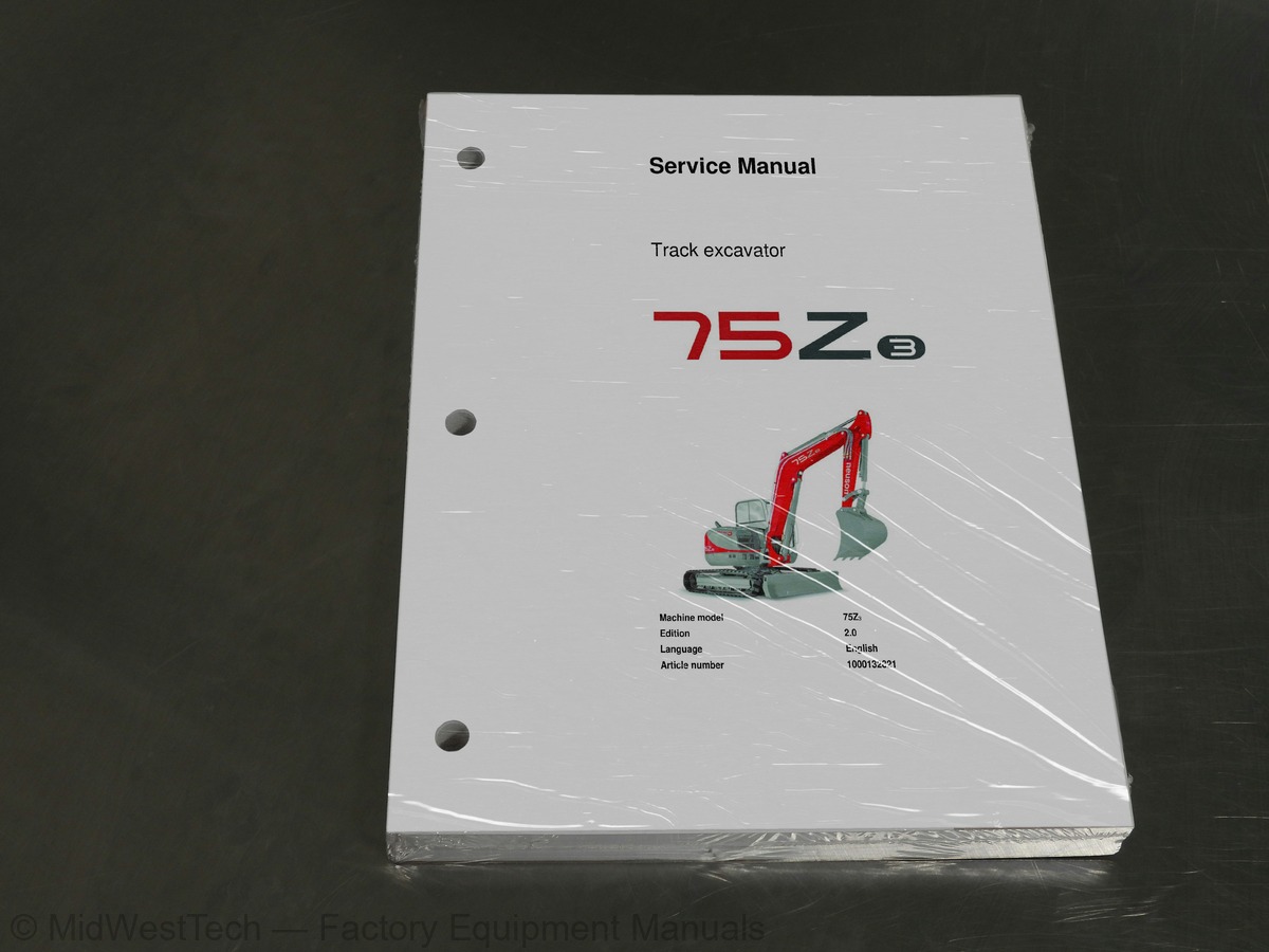
Wacker Neuson 75z3 Track Excavator Service Manual
329 pages · Publication 1000132821
Added to your cart. View cart
- Models
- 75z3
- Manual type
- Service Manual
- Pages
- 329
- Publication
- 1000132821
- Condition
- Brand new
What's inside
From the manual's own table of contents: 67 sections, 310 entries. See sample pages (PDF, 705 KB)
General48 topics
- Important information on this service manual
- Identification of warnings and dangers
- Designated use and exemption from liability
- Type labels and component numbers
- Machine overview
- Cab overview
- Up to serial no.: AD07209
- From serial no.: AH00646
- Cab (legend)
- Instrument panel overview
- Instrument panel (legend)
- Engine compartment overview up to serial no. AD07209
- Engine compartment overview from serial no. AH00646
- Chassis overview
- Tilting the cab
- Summer/winter operation
- Preheated fresh air
- Auxiliary hydraulics/boom swivel pedal
- Chassis
- Engine
- Fuel injection pump
- Capacities
- Tightening torques
- Hydraulic system
- Auxiliary hydraulics oil flow*
- Screwable hose burst valve
- Undercarriage and swivel unit
- Stabiliser blade
- Electric system
- Fuse box in instrument panel
- Main fuse box with relays up to serial no. AD07209
- Relays
- Main fuse box with relays from serial no. AH00646
- Noise levels
- Vibration
- Coolant compound table
- Model-specific tightening torques
- General tightening torques
- Tightening torques for hydraulic screw connections (dry assembly)
- Tightening torques for high-resistance screw connections
- Dimensions model 75Z3
- Lift capacity table 75Z3
- Lift capacity table 75Z 3 with long stick
- Lift capacity table 75Z 3 with counterweight
- Lift capacity table 75Z 3 with long stick and counterweight
- Kinematics
- Fluids and lubricants
- Additional oil change and filter replacement (hydraulics)
Maintenance label1 topic
- Explanation of symbols on the maintenance label
Service package2 topics
- Up to serial no. AD07209
- From serial no. AH00646
Fuel system8 topics
- Specific safety instructions
- Refuelling
- Stationary fuel pumps
- Diesel fuel specification
- Bleeding the fuel system
- Emptying the fuel tank
- Fuel prefilter with water separator
- Replacing the fuel filter
Engine lubrication system4 topics
- Checking the oil level
- Filling up engine oil
- Changing engine oil
- Replacing the engine oil filter cartridge
Cooling system2 topics
- Checking/filling up coolant
- Draining coolant
Air filter2 topics
- Replacing the filter
- Functional check once a week of the dust valve
V-belt4 topics
- Checking V-belt tension
- Retightening the V-belt
- Checking the V-belt of the air conditioning system
- Tightening the V-belt of the air conditioning system
Pressure check8 topics
- General
- Checking pilot control pressure
- Pressure check of variable displacement pump P1
- Pressure check of variable displacement pump P2
- Pressure check of gear pump P3
- Secondary pressure limiting valve of the gear motor
- Measuring ports: overview
- Primary pressure limiting valves
Hydraulic system5 topics
- Checking the hydraulic oil level
- Filling up hydraulic oil
- Changing hydraulic oil
- Monitoring the hydraulic oil reflux filter
- Checking hydraulic pressure lines
Travelling drive2 topics
- Checking the oil level and filling up oil
- Draining oil
Chains43 topics
- Checking chain tension
- Setting the chains
- Lubrication work
- Lubrication points on the swivelling console
- Boom lubrication points
- Lubrication points on the stick
- Lubrication strip
- Maintenance of attachments
- Service and maintenance work at regular intervals
- Instructions concerning specific components
- Alternator
- Battery
- Jump-starting the engine
- Replacing the cab filter
- General maintenance work
- Cleaning
- General instructions for all areas of the machine
- Inside the cab
- Exterior of the machine
- Engine compartment
- Screw connections and attachments
- Engine 4TNV98-VNS (up to serial no. AD07209 American Tier 2)
- Fuel system
- Removing the valve cover
- Checking and adjusting valve clearance
- Checking valve clearance
- Setting zero play of the valve bridge
- Setting valve clearance
- Tightening order for cylinder head bolts
- Checking the injection nozzles
- Pressure check
- Checking the nozzle jet
- Injection time
- Checking injection time
- Setting injection time
- Replacement of fuel injection pump
- Adjusting engine revs
- Compression
- Checking the coolant thermostat
- Checking the thermal switch
- Oil pressure switch
- Checking the coolant circuit
- Engine 4TNV98-ZVNS from serial no. AH00646
Electronic engine control (E-ECU)1 topic
- Features
Show all 68 sections
Error diagnosis56 topics
- connector assignment
- Important information on the ECU maintenance wiring harness
- Flash code 7 – proportional injection pump solenoid (control rack)
- Related DTC (Diagnostic Trouble Codes)
- Diagnosis description
- Flash code 5 – manual throttle
- Related DTC
- Work description
- Flash code 4-1 ECU internal
- Flash code 2-4 – sensor 5 V
- Flash code 2-3 – power supply voltage
- (1) P0562/1: power supply voltage error (voltage too low)
- DTC detection conditions
- Troubleshooting
- (2) P0563/0: power supply voltage error (voltage too high)
- Flash code 6 – revs sensor
- Flash code 1-1 – backup revs sensor
- Flash code 9 – overspeed error
- Flash code 1-5 – preheating relay
- Flash code 1-4 – CSD (cold start device) solenoid coil
- Flash code 1-3 – EGR (exhaust gas recirculation) valve
- Flash code 2-1 – oil pressure switch and 3-1 – oil pressure drop error
- Flash code 8 – proportional injection pump solenoid (control rack)
- Flash code 1-6 – main relay
- Flash code 1-2 – CAN (Controller Area Network) communication
- Automatic revs setting
- How it works
- Hydraulic pump AP2D36LV3RS6-875-P
- Pump unit: exploded view
- Pilot oil supply unit
- Main valve block
- Ports
- Legend
- Main valve block diagram
- Pressure limiting valves
- Pump assignment
- Drive counterbalancing system
- Pump assignment for drive counterbalancing
- hydraulics
- Bucket pre-tension
- Boom summation – raise
- Check valve (load retaining valve)
- Stick ram summation – extend
- Pilot valves
- Joystick
- Pilot valve (driving)
- Pilot valve for auxiliary hydraulics
- Pilot valve for stabiliser blade
- Valves
- 7/2 directional valve (changeover valve)
- 4/3 directional valve
- Shuttle valve block
- Changeover valve for SAE/ISO controls (option)
- Drive up to serial number: AC 02793
- Function
- 2nd speed range function
Swivel unit2 topics
- Parking brake/multidisc brake function
- Anti Swing Back (ASB) valve
Relays1 topic
- Use, mode of function
Joystick tip switches2 topics
- Joystick (left)
- Joystick (right)
Engine – chassis A4 wiring harness 1000116497 up to serial no. AD0720942 topics
- Engine – chassis A4 wiring harness 1000173970 from serial no. AH00646
- Switches A4 wiring harness 1000125106 (legend)
- Switches A4 wiring harness 1000125106
- Wiring harness 1000109629: cab roof
- Wiring harness 1000109628: armrest
- Wiring harness 1000116138: boom working light
- Wiring diagram A3 up to serial no. AD07209 (legend)
- Wiring diagram A3 up to serial no. AD07209
- Wiring diagram A4 from serial no. AH00646 (legend)
- Wiring diagram A4 (1) from serial no. AH00646
- Wiring diagram A4 (2) from serial no. AH00646
- Engine – chassis A3 wiring harness 1000109624 up to serial no. AD07209
- Engine – chassis A3 wiring harness 1000173970 from serial no. AH00646
- Wiring harness 1000125106 switches A3 (legend)
- Wiring harness 1000125106 switches A3
- Wiring harness 1000109629: cab roof A3
- Wiring harness 1000109628: armrest A3
- Wiring harness 1000116138: boom working light A3
- Air conditioning
- Specifications
- Installation: overview
- Components
- Filling up the air conditioning system
- Maintenance
- Air-suspension seat
- Connections
- Counterweight
- Long stick
- Control circuit (pipework) connections for grab
- 3rd control circuit connections
- Auxiliary hydraulics connections
- Quickhitch couplings
- Attachments
- Fuel-filling pump
- Connections up to serial no. AD07209
- Central lubrication system
- Position
- Adjusting breaks and lubrication times
- Repair in case of clogging
- Service valve
- Safe load indicator D (safety valve for boom)
- Diagram
Drive interlock (antitheft protection)3 topics
- Disabling the drive interlock
- Enabling the drive interlock
- Programming
Proportional controls7 topics
- Overview
- Wiring harness
- Control unit
- Control valve plug assignment
- Safety features
- Measures to be taken in case of malfunctions
- Diagnosis display
Inside this manual
Real pages from this service manual (329 pages). Open the sample pages (PDF, 703 KB)

- Specifications, page 46: SERV-HB 75Z3 EN – Edition 2.0 *75Z3s210.fm
- Troubleshooting, page 136: SERV-HB 75Z3 EN – Edition 2.0 * 7003s430.fm
- Diagram, page 171: SERV-HB 75Z3 EN – Edition 2.0 * 7003s430.fm
- Color page, page 205: SERV-HB 75Z3 EN – Edition 2.0 *75Z3s510.fm
- Color page, page 95: SERV-HB 75Z3 EN – Edition 2.0 *75Z3s314.fm
- Foldout diagram (color), page 243: Hydraulic system
Other manuals for this machine
Save 10% on 2 manuals, 15% on 3 or more. Other manuals for the 75z3 are listed below. Editions cover different serial number ranges: check the serial coverage and tick only the ones that match your machine.
Added to your cart. View cart
This is a service manual
Here's how it compares to the other manual types.
Service manual
Factory repair procedures and technical information such as specifications, troubleshooting, and wiring and hydraulic diagrams, for the models and systems the manual covers. See What's inside for its topics.
Operator's manual
Safe operation, controls, maintenance schedules, lubrication points, inspections, and basic checks. Repair procedures are in the service manual.
Parts manual
Illustrated diagrams with factory part numbers for identifying components and ordering parts. Repair procedures are in the service manual.
Engine service manuals are sometimes sold separately, since certain machine models were offered with more than one engine option.
What it's used for
Factory manual for in-house farm and construction shop use. Straightforward, complete, and easy to follow. It contains the OEM information dealership service departments and parts counters use to diagnose problems, identify components, and perform maintenance or repairs correctly.
Service shops and owner/operators who repair their own equipment
Identifying correct parts and seeing how assemblies come apart and go back together
Keeping equipment running with less downtime
Factory manual, 329 pages
Quantity one is the manual described above.
Fast free USA shipping
Ships in 1 business day.
60-day returns
Free if the mistake is ours. A manual ordered in error must come back unopened in its shrink-wrap; you pay return shipping and a 20% restocking fee applies. Return policy
Binder not included
Manuals over about 300 pages may need a standard 3-ring binder, which you can buy locally to keep the pages organized for shop use.
Questions about model, serial number, engine coverage or contents? Contact us before purchasing and we'll help confirm it's the right manual. Please verify the manual type, machine model, serial number range and engine coverage before purchasing: manuals ordered in error carry a 20% restocking fee (return policy).