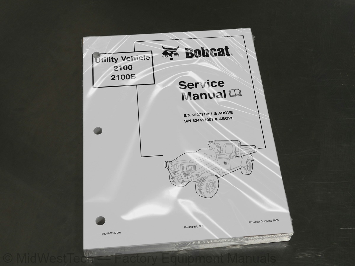
Bobcat 2100, 2100S Utility Vehicle Service Manual
382 pages · Publication 6901987_5_09
Added to your cart. View cart
What's inside
From the manual's own table of contents: 132 sections, 498 entries. See sample pages (PDF, 383 KB)
Storage2 topics
- Preparing the Vehicle for Extended Storage
- To Return Vehicle to Service
Front Body Repair3 topics
- Abrasions and Haze
- Light Scratches
- Large Scratches and Abrasions
Front Body Components6 topics
- Dashboard Removal
- Dashboard Installation
- Front Body Removal
- Front Fender Removal
- Front Fender Installation
- Front Body Installation
Seat1 topic
- Seat Adjustment
Front Seat Support2 topics
- Front Seat Support Removal
- Front Seat Support Installation
Rear Seat Support2 topics
- Rear Seat Support Removal
- Rear Seat Support Installation
Cargo Bed3 topics
- Cargo Bed Removal
- Cargo Bed Installation
- Bed Stop Bumper Adjustment
Rear Fender2 topics
- Rear Fender Removal
- Rear Fender Installation
Tailskirt2 topics
- Tailskirt Removal
- Tailskirt Installation
Receiver Hitch2 topics
- Receiver Hitch Removal
- Receiver Hitch Installation
Floor Mat2 topics
- Floor Mat Removal
- Floor Mat Installation
Brake Pedal2 topics
- Brake Pedal Removal
- Brake Pedal Installation
Accelerator Pedal2 topics
- Accelerator Pedal Removal
- Accelerator Pedal Installation
Show all 132 sections
Brake Drum Removal2 topics
- Front Wheel Brake Drum Removal
- Rear Wheel Brake Drum Removal
Brake Shoe Removal2 topics
- Front Brake Shoe Removal
- Rear Brake Shoe Removal
Brake Shoe Installation2 topics
- Front Brake Shoe Installation
- Rear Brake Shoe Installation
Brake Drum Installation2 topics
- Front Wheel Brake Drum Installation
- Rear Wheel Brake Drum Installation
Brake Cluster Assembly Replacement4 topics
- Front Brake Cluster Assembly Removal
- Front Brake Cluster Assembly Installation
- Rear Brake Cluster Assembly Removal
- Rear Brake Cluster Assembly Installation
Wheel Cylinder Replacement4 topics
- Front Wheel Cylinder Removal
- Front Wheel Cylinder Installation
- Rear Wheel Cylinder Removal
- Rear Wheel Cylinder Installation
Brake Shoe Adjuster Replacement4 topics
- Front Brake Shoe Adjuster Removal
- Front Brake Shoe Adjuster Installation
- Rear Brake Shoe Adjuster Removal
- Rear Brake Shoe Adjuster Installation
Hydraulic Line and Hose Replacement8 topics
- Front Brake Line Removal
- Front Brake Line Installation
- Front Brake Hose Assembly Removal
- Front Brake Hose Assembly Installation
- Rear Brake Line Removal
- Rear Brake Line Installation
- Rear Brake Hose Removal
- Rear Brake Hose Installation
Master Cylinder And Bell Crank Replacement4 topics
- Bell Crank Removal
- Bell Crank Installation
- Master Cylinder Removal
- Master Cylinder Installation
Bleeding the Hydraulic Brake System2 topics
- Purging the Hydraulic System
- Filling the Hydraulic System
Park Brake System5 topics
- Park Brake Cable Removal
- Park Brake Cable Installation
- Park Brake Handle Removal
- Park Brake Handle Installation
- Park Brake Adjustment
Steering Wheel2 topics
- Steering Wheel Removal
- Steering Wheel Installation
Steering Column4 topics
- Steering Column Removal
- Steering Column Disassembly
- Steering Column Assembly
- Steering Column Installation
Rack and Pinion4 topics
- Rack and Pinion Removal
- Rack and Pinion Disassembly
- Rack and Pinion Assembly
- Rack and Pinion Installation
Front Suspension2 topics
- Lubrication
- Wheel Alignment
Front Suspension Components6 topics
- Kingpin and Steering Spindle Removal
- Kingpin and Steering Spindle Installation
- A-Arm Removal
- A-Arm Installation
- Shock Absorber Removal
- Shock Absorber Installation
Front Wheel Bearings and Hubs3 topics
- Front Wheel Free Play Inspection
- Front Wheel Bearings and Hub Removal
- Front Wheel Bearings and Hub Installation
Shock Absorbers1 topic
- Shock Absorber Removal and Inspection
Multi-Leaf Springs2 topics
- Multi-Leaf Spring Removal
- Multi-Leaf Spring Installation
Snubber2 topics
- Snubber Removal
- Snubber Installation
Master Cylinder1 topic
- Brake Fluid
Engine Oil3 topics
- Engine Oil Level Check
- Engine Oil and Filter Change
- Oil Viscosity
Electrical Circuits10 topics
- Starter Circuit
- Generator Circuit
- Engine Ignition Circuit
- Engine Kill Circuit
- Reverse Buzzer Circuit
- Low Oil Warning Circuit
- Lockout Cam Circuit
- Fuel Gauge and Sending Unit Circuit
- Hour Meter Circuit
- Lighting Circuit
Circuit Testing8 topics
- Testing the Starter Circuit and Generator Circuit
- Testing the Engine Ignition Circuit
- Testing the Engine Kill Circuit
- Testing the Reverse Buzzer Circuit
- Testing the Low Oil Warning Circuit
- Testing the Lockout Cam Circuit
- Testing the Fuel Gauge and Sending Unit Circuit
- Testing the Lighting Circuit
Test Procedures1 topic
- Index of Test Procedures
Light Switch2 topics
- Testing the Light Switch
- General Information
Section 13 - FE400 Engine3 topics
- Before Servicing
- Lubrication System
- Spark Plug
Cylinder2 topics
- Breather Valve (Reed Valve)
- Valve Clearance Check and Adjustment
Crankcase3 topics
- Engine Removal
- Crankcase Cover Removal
- Oil Level Sensor
Ignition Coil and Flywheel1 topic
- Crankcase Cover Installation
Engine Installation2 topics
- Torque Specifications
- Adjustment and Settings
Carburetor2 topics
- Main Jet Elevation/Size Chart
- Changing the Main Jet
Engine Control Linkage5 topics
- Accelerator Rod
- Governor Cable
- Accelerator Cable
- Closed Throttle or Idle Adjustment
- Engine RPM Adjustment
Choke and Air Intake System8 topics
- Choke Cable Removal
- Choke Cable Installation
- Air Box Removal
- Air Box Installation
- Intake Duct Repair
- Intake Duct Removal
- Intake Duct Installation
- Air Filter
Fuel Filters2 topics
- Fuel Filter Removal
- Fuel Filter Installation
Fuel Pump5 topics
- Fuel Pump Removal
- Fuel Pump Disassembly
- Fuel Pump Cleaning and Inspection
- Fuel Pump Assembly
- Fuel Pump Installation
Fuel Tank3 topics
- Fuel Tank Removal
- Fuel Tank Storage or Disposal
- Fuel Tank Installation
Muffler2 topics
- Muffler Removal
- Muffler Installation
Axle Shaft3 topics
- Axle Shaft, Bearing, and Oil Seal Removal
- Axle Bearing Removal
- Axle Shaft, Bearing, and Oil Seal Installation
Forward/Reverse Shifter Cable3 topics
- Forward/Reverse Shifter Cable Removal
- Forward/Reverse Shifter Cable Installation
- Forward/Reverse Shifter Cable Adjustment
Differential Lock System3 topics
- Differential Lock System Inspection
- Differential Lock Cable Removal
- Differential Lock Cable Installation
Drive Belt2 topics
- Drive Belt Removal
- Drive Belt Installation
Drive Clutch6 topics
- Drive Clutch Removal
- Drive Clutch Cleaning and Inspection
- Drive Clutch Disassembly
- Inspection of Drive Clutch Parts
- Drive Clutch Assembly
- Drive Clutch Installation
Driven Clutch5 topics
- Driven Clutch Removal
- Driven Clutch Disassembly
- Driven Clutch Inspection
- Driven Clutch Assembly
- Driven Clutch Installation
Special Engine Service Tools Available2 topics
- Recommended Replacement Parts For Engine Teardown
- Mechanical Systems
Cylinder Components13 topics
- Cylinder Head
- Cylinder Shroud Removal
- Rocker Arm and Push Rod Removal
- Cylinder Head Removal
- Valve Removal
- Cylinder Head Cleaning and Inspection
- Valve Guides
- Valve Seats
- Valves
- Rocker Arm and Rocker Shaft inspection
- Push Rod Inspection
- Cylinder Head Installation
- Installation of Remaining Engine Components
Crankcase Components1 topic
- Camshaft and Hydraulic Lifters
Oil Pump1 topic
- Oil Pressure Relief Valve
Crankshaft and Counterbalance4 topics
- Counterbalance Weight
- Oil Screen
- Ball Bearing
- Oil Seals
Service Specifications1 topic
- Specifications for Resizing Cylinder Bore
Component Disassembly7 topics
- Differential Gear Lock Housing Disassembly
- Governor Gear Disassembly
- Differential Gear Case Disassembly
- Shifter Fork Disassembly
- Synchronizer Gear Disassembly
- Intermediate Gear Disassembly
- Idler Shaft Disassembly
Component Assembly7 topics
- Idler Shaft Assembly
- Intermediate Gear Assembly
- Synchronizer Gear Assembly
- Shifter Fork Assembly
- Differential Gear Case Assembly
- Governor Gear Assembly
- Differential Gear Lock Housing Assembly
Unitized Transaxle Assembly149 topics
- accelerator
- air box
- air filter 14-1
- armature
- axle
- bed, cargo
- belt, drive
- body, front
- brakes
- breather valve (reed valve) 18-9
- camshaft
- camshaft and hydraulic lifter
- carburetor
- cargo bed
- CAUTION
- cleaning
- clutch (torque converter) troubleshooting 17-3
- clutch, drive
- clutch, driven
- column, steering
- commutator
- connecting rod
- counterbalance
- counterbalance guide shaft
- crankcase 18-20
- crankshaft
- cylinder block 18-26
- cylinder head 18-4
- cylinder shroud
- DANGER
- dashboard
- differential gear case
- differential lock
- differential lock housing
- diode
- diode, headlight
- drive belt
- drive clutch
- driven clutch
- electrical system
- engine
- engine oil 10-4
- exhaust system 14-1
- fender, front
- fender, rear
- field coil
- fluid, brake 10-4
- flywheel
- forward/reverse
- front body
- fuel filter 14-1
- fuel gauge
- fuel gauge sending unit circuit
- fuel gauge/hour meter
- fuel level sending unit 12-22
- fuel lines 14-1
- fuel shut-off valve 14-28
- fuel tank
- fueling instructions 10-7
- fuse
- governor gear
- ground straps
- headlight bulb
- headlight diode
- headlight switch
- headlights
- hour meter
- hydraulic lifter
- hydrometer test 11-21
- idler shaft
- ignition
- ignition coil
- inspection
- intake duct
- intermediate gear
- key switch
- kill circuit, engine
- kill wire, engine
- leaf springs, multi 9-1
- link rod
- lockout cam
- low oil warning light
- maintenance
- master cylinder
- muffler
- neutral lockout 16-3
- oil light
- oil pump
- oil seal
- oil viscosity 10-7
- oil, engine 10-4
- park brake
- pedal, accelerator
- pedal, brake
- periodic lubrication schedule 10-2
- periodic service schedule 10-1
- piston
- piston and connecting rod
- piston pin
- piston ring
- push rod
- rack and pinion
- receiver hitch
- reed valve
- reverse buzzer
- rocker arm
- rocker arm and push rod
- rocker shaft
- RPM adjustment 14-10
- RPM limiter
- safety
- seat
- serial number, vehicle 3-1
- service schedule
- shifter fork
- shock absorber
- snubber
- solenoid
- specifications
- starter/generator
- starter/generator circuit
- steering
- steering column
- steering wheel
- storage
- suspension, front
- suspension, rear
- synchronizer gear
- test procedure
- test procedures, index of 11-19
- testing
- tire
- torque converter
- torque specifications 18-48
- trailer hitch
- transaxle
- troubleshooting
- unitized transaxle 19-1
- valve (cylinder)
- valve guide
- valve seat
- valves (engine)
- voltage limiter
- voltage regulator
- WARNING
- wheel
- wheel cylinder
- wire continuity testing 11-29
- wiring diagram 11-5
Inside this manual
Real pages from this service manual (382 pages). Open the sample pages (PDF, 382 KB)
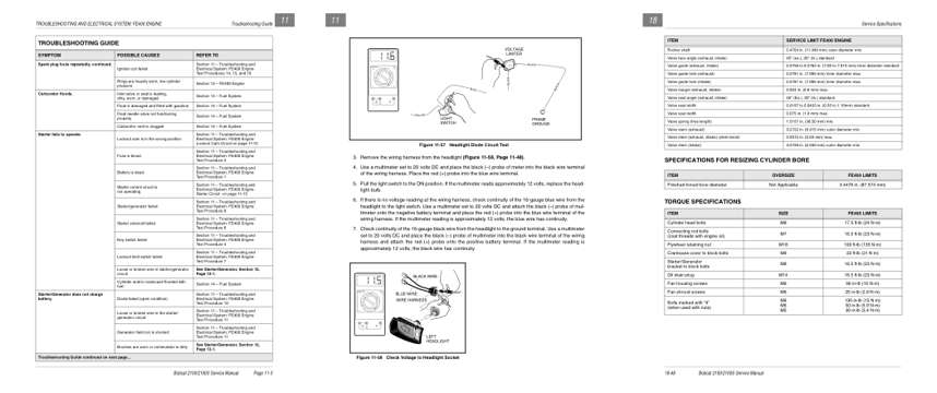
- Troubleshooting, page 123: TROUBLESHOOTING AND ELECTRICAL SYSTEM: FE400 ENGINE
- Diagram, page 168: 3. Remove the wiring harness from the headlight (Figure 11-58, Page 11-48).
- Specifications, page 338: Service Specifications
Other manuals for this machine
Save 10% on 2 manuals, 15% on 3 or more. Other manuals are listed below. Editions cover different serial number ranges: check the serial coverage and tick only the ones that match your machine.
Added to your cart. View cart
This is a service manual
Here's how it compares to the other manual types.
Service manual
Factory repair procedures and technical information such as specifications, troubleshooting, and wiring and hydraulic diagrams, for the models and systems the manual covers. See What's inside for its topics.
Operator's manual
Safe operation, controls, maintenance schedules, lubrication points, inspections, and basic checks. Repair procedures are in the service manual.
Parts manual
Illustrated diagrams with factory part numbers for identifying components and ordering parts. Repair procedures are in the service manual.
Engine service manuals are sometimes sold separately, since certain machine models were offered with more than one engine option.
What it's used for
Factory manual for in-house farm and construction shop use. Straightforward, complete, and easy to follow. It contains the OEM information dealership service departments and parts counters use to diagnose problems, identify components, and perform maintenance or repairs correctly.
Service shops and owner/operators who repair their own equipment
Identifying correct parts and seeing how assemblies come apart and go back together
Keeping equipment running with less downtime
Factory manual, 382 pages
Quantity one is the manual described above.
Fast free USA shipping
Ships in 1 business day.
60-day returns
Free if the mistake is ours. A manual ordered in error must come back unopened in its shrink-wrap; you pay return shipping and a 20% restocking fee applies. Return policy
Binder not included
Manuals over about 300 pages may need a standard 3-ring binder, which you can buy locally to keep the pages organized for shop use.
Other editions and similar models
Questions about model, serial number, engine coverage or contents? Contact us before purchasing and we'll help confirm it's the right manual. Please verify the manual type, machine model, serial number range and engine coverage before purchasing: manuals ordered in error carry a 20% restocking fee (return policy).