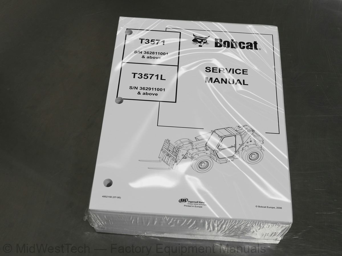
Bobcat T3571, T3571L Telehandler Service Manual
1,034 pages · Publication 4852150_07_06
Added to your cart. View cart
What's inside
From the manual's own table of contents: 47 sections, 543 entries. See sample pages (PDF, 424 KB)
FOReWORD II13 topics
- SAFETY INSTRUCTIONS V
- Serial Number LocationS VII
- Delivery Report VII
- Identification of the telescopic handler VIII
- SAFETY AND MAINTENANCE 10-01
- HYDRAULIC SYSTEM 20-01
- HYDROSTATIC SYSTEM 30-01
- DRIVE SYSTEM 40-01
- MAIN FRAME 50-01
- ELECTRICAL SYSTEM AND ANALYSIS 60-01
- ENGINE SERVICE 70-01
- HEATING, VENTILATION, AIR CONDITIONING 80-01
- SPECIFICATIONS SPEC-01
This manual is for the Bobcat Telescopic Handler mechanic. It provides necessary servicing and adjustment procedures for68 topics
- A general inspection of the following items must be made after the Telescopic Handler has had service or repair
- SAFETY INSTRUCTIONS
- Before Operation
- SAFETY INSTRUCTIONS (CONT’D)
- Safe Operation Is The Operator’s Responsibility
- Safe Operation Needs A Qualified Operator
- A Qualified Operator Must Do The Following
- Serial Number LocationS
- Telescopic Handler Serial Number
- Figure 1
- Engine Serial Number
- Figure 2
- Other Serial Numbers
- Delivery Report
- Figure 3
- Identification of the telescopic handler
- Figure 4
- SAFETY AND MAINTENANCE
- AIR CLEANER SERVICE 10-60-1
- Replacing Filter Element 10-60-1
- OPTIONAL APPROVED BOOM STOP 10-150-1
- Installing The Approved Boom Stop 10-150-1
- Checking Oil Level (Front Differential) 10-110-2
- Checking Oil Level (Front Differential) 10-111-2
- ENGINE COOLING SYSTEM 10-70-1
- Checking The Coolant Level 10-70-1
- Opening And Closing The Engine Cover 10-160-1
- ENGINE LUBRICATION SYSTEM 10-90-1
- Checking Engine Oil 10-90-1
- Filling The Fuel Tank 10-80-1
- SAFETY AND MAINTENANCE (Cont’d)
- HYDRAULIC/HYDROSTATIC SYSTEM 10-100-1
- Checking And Adding Fluid 10-100-1
- LIFTING AND BLOCKING THE Telescopic Handler 10-10-1
- OPERATOR CAB 10-20-1
- SERVICE SCHEDULE 10-50-1
- TIRE MAINTENANCE 10-130-1
- TOWING THE Telescopic Handler 10-40-1
- Preparing for towing 10-40-1
- TRANSPORTING THE Telescopic Handler 10-30-1
- LIFTING AND BLOCKING THE Telescopic Handler
- OPERATOR CAB
- OPERATOR CAB (CONT’D)
- TRANSPORTING THE Telescopic Handler
- TOWING THE Telescopic Handler
- Preparing for towing
- TOWING THE Telescopic Handler (CONT’d)
- As the machine’s handbrake is tightened by lack of pressure, this operation involves releasing the brake mechanically
- Releasing the handbrake (For S/N 362812001 and Above, S/N 362912001 and Above)
- As the machine’s brakes are tightened by lack of hydraulic pressure (= handbraked position), this operation involves rel
- Towing the Telescopic Handler
- Tow the Telescopic Handler at slow speed
- SERVICE SCHEDULE
- Maintenance work must be done at regular intervals. Failure to do so will result in excessive wear and early failures. T
- AIR CLEANER SERVICE (CONT’D)
- ENGINE COOLING SYSTEM
- ENGINE COOLING SYSTEM (CONT’D)
- FUEL SYSTEM
- ENGINE LUBRICATION SYSTEM
- ENGINE LUBRICATION SYSTEM (CONT’D)
- HYDRAULIC/HYDROSTATIC SYSTEM
- HYDRAULIC/HYDROSTATIC SYSTEM (CONT’D)
- Axle Pivots - Top and bottom (Item 1) [Figure 10-121- 1] all four wheels
- TIRE MAINTENANCE
- LIFT CYLINDER (Cont'd)
- Rotate the battery disconnect switch (Item 1) [Figure 20-20-6] to the right to disconnect the power supply from the b
- The side window (Item 1) and frame opening (Item 2) [Figure 20-20-7] must be protected from sparks
- The cylinder rod must be wrapped with a damp welding blanket (Item 1) [Figure 20-20-8] to prevent damage
Parts Identification12 topics
- BUCKET POSITIONING CYLINDER
- BUCKET POSITIONING CYLINDER (Cont'd)
- BUCKET POSITIONING CYLINDER (CONT’D)
- BUCKET POSITIONING CYLINDER (Cont'd)
- EXTENSION CYLINDER (Cont'd)
- EXTENSION CYLINDER (CONT’D)
- TILT CYLINDER
- TILT CYLINDER (CONT’D)
- TILT CYLINDER (Cont'd)
- STEERING CYLINDER (FRONT) (For S/N 362812001 and Above, S/N 362912001 and Above)
- STEERING CYLINDER (FRONT) (For S/N 362812001 and Above, S/N 362912001 and Above) (CONT’D)
- Parts Identification
MAIN RELIEF VALVE61 topics
- MAIN RELIEF VALVE (CONT’D)
- QUICK TACH CYLINDER (Cont'd)
- FRAME LEVELING CYLINDER
- FRAME LEVELING CYLINDER (CONT’D)
- STEERING MODE VALVE BLOCK (CONT’D)
- STEERING MODE VALVE BLOCK (Cont'd)
- BRAKE VALVE
- BRAKE VALVE (CONT’D)
- GEAR PUMP
- GEAR PUMP (Cont'd)
- GEAR PUMP (CONT’D)
- GEAR PUMP (Cont'd)
- FAN MOTOR (CONT’D)
- HYDRAULIC RESERVOIR
- HYDRAULIC RESERVOIR (CONT’D)
- STEERING VALVE (CONT’D)
- STEERING VALVE (Cont'd)
- HYDRAULIC CONTROL VALVE
- HYDRAULIC CONTROL VALVE (CONT’D)
- Locate the telescoping valve section (Item 1) [Figure 20-170-2] on the control valve
- A test harness (Item 1) [Figure 20-170-3] (MEL 1609: p/n 6679457) must be installed in between the male and female co
- With the telescopic function switch (Item 1) [Figure 20-170-4] in the minimum (back) position check that the voltage
- Locate the test fitting (Item 1) [Figure 20-170-5] and remove the cap
- Install a 1000 PSI (70 bar) gauge on the test fitting [Figure 20-170-6]
- Remove the hose (Item 1) [Figure 20-170-7] from the control valve, and install a tee fitting
- Install a 500 PSI (35 bar) gauge on the tee fitting [Figure 20-170-8]
- With adequate room in front of the machine, start the engine, lower the restraint bar (if equipped) and run the engi
- If the telescopic function does not work, with the engine running unplug the controller connector (Item 1) [Figure 2
- If the telescopic function does not work, remove the two screws (Item 1) and remove the cover (Item 2) [Figure 20-17
- Manually push and pull the spool (Item 1) [Figure 20- 170-12] to test the movement of the telescopic function in bot
- Locate the auxiliary valve section (Item 1) [Figure 20- 170-14] on the control valve
- A test harness (Item 1) [Figure 20-170-3] (MEL 1609: p/n 6679457) must be installed in between the male and female co
- With the auxiliary function switch (Item 1) [Figure 20- 170-4] in the minimum (back) position check that the voltage
- Locate the test fitting (Item 1) [Figure 20-170-17] and remove the cap
- Install a 1000 PSI (70 bar) gauge on the test fitting [Figure 20-170-18]
- Remove the hose (Item 1) [Figure 20-170-19] from the control valve, and install a tee fitting
- Install a 500 PSI (35 bar) gauge on the tee fitting [Figure 20-170-20]
- With adequate room in front of the machine, start the engine, lower the restraint bar (if equipped) and run the engi
- If the auxiliary function does not work, with the engine running unplug the controller connector (Item 1) [Figure 20
- If the auxiliary function does not work, remove the two screws (Item 1) and remove the cover (Item 2) [Figure 20-170
- Manually push and pull the spool (Item 1) [Figure 20- 170-24] to test the movement of the auxiliary function in both
- PORT RELIEF VALVES
- FLOW CONTROL VALVE
- JOYSTICK
- JOYSTICK (CONT’D)
- PARKING BRAKE
- PARKING BRAKE (CONT’D)
- PILOT PRESSURE LOCK OUT VALVE
- PILOT PRESSURE LOCK OUT VALVE (CONT’D)
- ACCUMULATOR
- HYDROSTATIC DRIVE MOTOR (Cont'd)
- Parts Identification
- Parts Identification (Cont’d)
- HYDROSTATIC DRIVE MOTOR (Cont'd)
- HYDROSTATIC PUMP
- HYDROSTATIC PUMP (CONT’D)
- HYDROSTATIC PUMP (Cont'd)
- Parts Identification
- Parts Identification (Cont’d)
- CUSTOMER PACKING LIST
- HYDROSTATIC PUMP (CONT’D)
Chart35 topics
- The following Troubleshooting Chart is provided for assistance in locating and correcting problems which are most common
- Pinion or Ring gear tooth broken
- Pinion teeth pitted
- Axle housing bent
- Worn or pitted bearings
- Oil leakage
- Excessive wear on input shaft splines
- Pinion teeth fatigue
- Side gear spline worn
- Thrust washer surface worn
- Inner diameter of tapered roller bearing worn
- Bent or broken half shaft
- Half shaft broken at wheel side
- Excessive gear load
- Incorrect gear adjustment (excessive play)
- Pinion nut loose
- Incorrect gear adjustment (insufficient play)
- Insufficient lubrication
- Contaminated oil
- Incorrect lubrication
- Worn bearings
- Operation at high temperature
- Low oil level
- Excessive use
- Overloaded
- Accident
- Normal Wear
- Lip seal damaged
- Pinion axle play
- Continuous overload
- Excessive pinion axle play
- Vehicle intensively operated or overloaded
- Wheel loose
- Beam housing bent
- Planetary Carrier Parts Identification
Wheel Hub Parts Identification2 topics
- Steering Knuckle Parts Identification
- Axle Housing/Drive Axle Parts Identification
Pinion Group Parts Identification6 topics
- Planetary Carrier Parts Identification
- Steering Knuckle Parts Identification
- Axle Housing/Drive Axle Parts Identification
- AXLE AND DIFFERENTIAL (FRONT) (For S/N 362812001 and Above, S/N 362912001 and Above)
- General Information
- Planetary Carrier Parts Identification
Planetary Carrier Disassembly1 topic
- Steering Knuckle and Drive Axle Parts Identification
Show all 47 sections
Differential assembly1 topic
- Setting Ring And Pinion Backlash
Planetary carrier Assembly37 topics
- AXLE AND DIFFERENTIAL (REAR) (For S/N 362812001 and Above, S/N 362912001 and Above)
- General Information
- Planetary Carrier Parts Identification
- AXLE AND DIFFERENTIAL (REAR) (For S/N 362812001 and Above, S/N 362912001 and Above) (CONT’D)
- Steering Knuckle Disassembly
- AXLE AND DIFFERENTIAL (REAR) (For S/N 362812001 and Above, S/N 362912001 and Above) (CONT’D)
- Differential Disassembly
- Bevel pinion Disassembly
- Bevel pinion Assembly
- Differential assembly
- Steering Knuckle Assembly
- Planetary Carrier Assembly
- AXLE AND DIFFERENTIAL (REAR) (For S/N 362812001 and Above, S/N 362912001 and Above) (CONT’D)
- Special tools
- FRONT AXLE WITHOUT FRAME LEVELING (Cont'd)
- AXLE PIVOT FRAME (CONT’D)
- STEERING ANGLE ADJUSTMENT (For S/N 362812001 and Above, S/N 362912001 and Above)
- DRIVESHAFT
- BOOM ASSEMBLY (Cont'd)
- INNER BOOM
- INNER BOOM (Cont'd)
- WEAR PADS (FRONT)
- WEAR PADS (REAR)
- WEAR PADS (REAR) (CONT’D)
- ENGINE COVER
- AIR INTAKE COWLING
- FUEL TANK (CONT’D)
- FUEL TANK (Cont'd)
- QUICK TACH
- QUICK TACH (Cont'd)
- REAR WEIGHTS
- FENDER
- PIVOT LINK (Cont'd)
- DASH COVER/STEERING COLUMN COVER
- DASH COVER/STEERING COLUMN COVER (Cont'd)
- JOYSTICK PANEL
- ELECTRICAL SYSTEM INFORMATION
ELECTRICAL SYSTEM INFORMATION (CONT’D)1 topic
- Fuses, Diodes & Relays
ELECTRICAL SYSTEM (CONT’D)103 topics
- ELECTRICAL SYSTEM INFORMATION (CONT’D)
- BATTERY
- BATTERY (Cont'd)
- ALTERNATOR
- ALTERNATOR (CONT’D)
- STARTER
- STARTER (CONT’D)
- LIGHTS
- LIGHTS (Cont'd)
- TRAVEL/SIGNAL LEVER
- TRAVEL/SIGNAL LEVER (CONT’D)
- INSTRUMENT PANEL
- SWITCH PANEL
- Switch PANEL (CONT’D)
- L.H. control panel plate
- R.H. control panel plate
- Screw
- Instrument panel
- Bezel
- Switch, beacon light
- Warning Switch
- Heating Control Valve
- Fan Speed Switch
- Bezel For outer left and right positions
- Bezel For middle positions
- Trailer turn indicator
- Steering mode indicator
- Steering mode switch
- Lever Switch
- Switch, head lamp
- Working light switch
- Fog light switch
- Blank Plug
- Switch, rear wiper/washer
- Switch, roof wiper (Option)
- Switch, transmission mode
- Locking switch
- Switch, aux. hydr
- Ignition Switch
- Set of keys (ignition)
- Knob
- Set of keys
- Stability indicator and wire harness
- Washer
- Support for frame leveling knob
- Switch (proportional)
- Spacer
- Plate
- Plug
- BRAKE LIGHT SWITCH
- FRONT WIPER MOTOR
- FRONT WIPER MOTOR (Cont'd)
- TOP WIPER MOTOR
- TOP WIPER MOTOR (Cont'd)
- REAR WIPER MOTOR
- REAR WIPER MOTOR (Cont'd)
- PEDAL ASSEMBLY
- PEDAL ASSEMBLY (CONT’D)
- INCHING SWITCH
- SERVICE SOFTWARE
- SERVICE SOFTWARE (CONT’D)
- Sensor supply voltage-sensor voltage out of range
- Software did not load properly- Restart program and reload software
- Inch pedal calibration failed- recalibrate the inch pedal
- Inch/brake potentiometer-no pedal setup done, value too low, value too high
- Engine speed pickup-engine speed missed when starting engine
- Propel current-short cut, open circuit
- F-N-R switch-short cut between forward and reverse
- Engine speed pickup-engine speed interrupted
- Hydro motor propel current-short cut, open circuit
- Creep drive calibration failed- recalibrate the creep drive potentiometer
- Creep drive potentiometer-value too low, value too high
- Motor speed pickup-motor speed interrupted
- FRAME LEVEL SPEED SWITCH
- FRAME LEVEL SPEED SWITCH (CONT’D)
- Longitudinal Stability Indicator Calibration
- ENGINE SERVICE
- ENGINE SERVICE (CONT’D)
- RECONDITIONING THE ENGINE 70-100-1
- ENGINE SERVICE (CONT’D)
- RECONDITIONING THE ENGINE 70-100-1
- TROUBLESHOOTING
- Chart
- The following troubleshooting chart is provided for assistance in location and correcting problems which are most common
- TROUBLESHOOTING (Cont'd)
- Chart (Cont'd)
- ENGINE SPEED CONTROL
- MUFFLER
- AIR CLEANER
- OIL COOLER/RADIATOR
- OIL COOLER/RADIATOR (CONT’D)
- ENGINE AND ENGINE MOUNTS
- ENGINE AND ENGINE MOUNTS (CONT’D)
- ENGINE COMPONENTS AND TESTING
- ENGINE COMPONENTS AND TESTING (CONT'D)
- ENGINE TIMING
- ENGINE/HYDROSTAT ASSEMBLY
- ENGINE/HYDROSTAT ASSEMBLY (CONT'D)
- FLYWHEEL AND HOUSING
- FLYWHEEL AND HOUSING (Cont'd)
- RECONDITIONING THE ENGINE
- Turbo Charger Troubleshooting
- RECONDITIONING THE ENGINE (CONT'D)
In an air conditioning system the refrigerant is circulated under pressure through five major components in a closed cir5 topics
- The compressor (Item 1) Page 80-10-3 takes in heated, low pressure refrigerant gas through the suction valve (low pressu
- Ambient air passing through the condenser removes the heat from refrigerant resulting in physical state change in the re
- The liquid refrigerant moves on to the receiver/drier (Item 3) Page 80-10-3 where impurities such as moisture and dirt a
- The expansion valve meters the amount of refrigerant into the evaporator coil (Item 5) Page 80-10-3. As the refrigerant
- The refrigerant cycle is completed when the heated low pressure gas is again drawn into the compressor
AIR CONDITIONING SYSTEM FLOW (Cont'd)16 topics
- COMPONENTS
- COMPONENTS (Cont'd)
- SAFETY
- REGULAR MAINTENANCE
- REGULAR MAINTENANCE (Cont'd)
- Cleaning The Condenser
- BASIC TROUBLESHOOTING
- BASIC TROUBLESHOOTING (Cont'd)
- GENERAL AIR CONDITIONING SERVICE GUIDELINES
- GENERAL AIR CONDITIONING SERVICE GUIDELINES (Cont'd)
- Measure the drained oil in a measuring cylinder
- Check the oil for contamination, dirt, metal shavings, or varnish color, discard the oil if contaminated
- Add new compressor oil through the suction side connector (Item 1) [Figure 80-60-24]
- Installation: Add 150-170 cc's of PAG oil
- Whenever the A/C system is opened to the atmosphere or there has been a leak in the system, the receiver/drier (Item 1)
- Never leave hose fittings, compressor fittings or components uncapped while working on the A/C system
Blower motor does not operate4 topics
- Blower motor operates normally, but air flow is insufficient
- Insufficient cooling although air flow and compressor operation are normal
- The compressor does not operate at all, or operates improperly
- Magnetic clutch related
Gauge Pressure Related Troubleshooting4 topics
- Normal compressor suction (low side) and discharge (high side) pressure at ambient temperatures of 86-96 degrees F (30-3
- High pressure side pressure: 210-265 PSI
- Low pressure side pressure: 15-33 PSI
- As a rule of thumb the high side pressure will be around eight times greater then the low side pressure
Gauge Pressure Related Troubleshooting (Cont’d)101 topics
- TEMPERATURE/PRESSURE
- Evaporator
- Pressures represent gas temperatures inside the coil. not the coil surface. For an estimate of the temperature of the ai
- Condenser
- Temperatures are not ambient temperatures but condensing temperatures. Add 40 degrees F. to the ambient temperature to g
- Example: Ambient Temperature=90 degrees F
- degrees F
- +40 degrees F
- Conditions and pressures will vary from system to system
- AIR CONDITIONING SERVICE
- SYSTEM CHARGING AND RECLAMATION
- SYSTEM CHARGING AND RECLAMATION (Cont'd)
- COMPRESSOR
- COMPRESSOR (Cont'd)
- CONDENSER
- RECEIVER/DRIER
- PRESSURE SWITCH
- EVAPORATOR/BLOWER UNIT
- EVAPORATOR/BLOWER UNIT (Cont'd)
- EXPANSION VALVE
- EXPANSION VALVE (Cont'd)
- HEATER ASSEMBLY
- HEATER ASSEMBLY (Cont'd)
- SPECIFICATIONS
- CONVERSIONS SPEC-70-1
- SPECIFICATIONS (CONT’D)
- MACHINE TORQUE SPECIFICATIONS SPEC-30-1
- Telescopic Handler SPECIFICATIONS
- All dimensions are shown in millimetres. Respective metric dimensions are given in millimeters enclosed by parentheses
- Telescopic Handler SPECIFICATIONS (CONT’D)
- *Rated Load Capacity can change depending on which approved attachment is used
- Travel Speed
- Low Range
- High Range
- Telescopic Handler SPECIFICATIONS (CONT’D)
- Optional Tires
- Type
- Fuel Tank
- Hyd./Hydros. System
- EQUIVIS ZS 46
- Eng. Cooling System
- Engine Oil Change w/Filter
- See oil chart
- Front Axle
- Rear Axle
- Front Reduction Gearbox
- Planetary Carrier
- Engine driven, 25 GPM (95 L/min)
- Auxiliary Flow
- Full compliment of instrumentation for engine, hydraulic and machine functions
- ENGINE SPECIFICATIONS
- All dimensions are given in inches. Respective metric dimensions are given in millimeters enclosed by parentheses
- General
- Cylinder Head
- Valve Guides
- Valve Guide Clearance In The Cylinder Head (Interference)
- ENGINE SPECIFICATIONS (Cont'd)
- All dimensions are given in inches. Respective metric dimensions are given in millimeters enclosed by parentheses
- Exhaust Valves
- Intake Valves
- Valve Springs
- Number Of Active Coils
- All dimensions are given in inches. Respective metric dimensions are given in millimeters enclosed by parentheses
- Rocker Shaft, Rockers And Bushings
- Pistons And Piston Rings
- All dimensions are given in inches. Respective metric dimensions are given in millimeters enclosed by parentheses
- Connecting Rods And Bearings
- Crankshaft
- ENGINE SPECIFICATIONS (Cont'd)
- All dimensions are given in inches. Respective metric dimensions are given in millimeters enclosed by parentheses
- Main Bearings
- Bearing Undersize Available
- Thrust Washers
- Camshaft And Thrust Washer
- Camshaft End Play (Production)
- Cylinder Block
- All dimensions are given in inches. Respective metric dimensions are given in millimeters enclosed by parentheses
- Cylinder Liners
- Fuel Injection Pump
- Fuel Injectors
- Fuel Lift Pump
- Electrically operated
- All dimensions are given in inches. Respective metric dimensions are given in millimeters enclosed by parentheses
- Timing Case And Timing Gears
- Fuel Pump Gear Number Of Teeth (Electronic)
- Fuel Pump Gear Bore (Electronic)
- Width Of Idler Gear And Bushing Assembly (Fitted)
- Flanged Bushing Inside Assembly (Fitted)
- Gear End Play (Production Limits)
- All dimensions are given in inches. Respective metric dimensions are given in millimeters enclosed by parentheses
- Oil Pump, Gear And Relief Valve
- End Play
- Turbocharger
- Flywheel
- All dimensions are given in inches. Respective metric dimensions are given in millimeters enclosed by parentheses
- Water Pump And Thermostat
- Engine Torque Component
- MACHINE TORQUE SPECIFICATIONS
- FT.-LBS
- MACHINE TORQUE SPECIFICATIONS (CONT’D)
- FT.-LBS
Torque for General SAE Bolts2 topics
- The following table shows standard torque specifications for bolts with zinc phosphate coating. Bolts purchased from Bob
- INCH. LBS.(Nm)
Torque For General Metric Bolts23 topics
- Thread Size (Dia. x Pitch)
- Material
- Head Mark 4
- Head Mark 7
- Head Mark 10
- HYDRAULIC CONNECTION SPECIFICATIONS
- Figure SPEC-50-15
- Figure SPEC-50-16
- HYDRAULIC CONNECTION SPECIFICATIONS (Cont'd)
- Figure SPEC-50-17
- Figure SPEC-50-18
- Figure SPEC-50-19
- * If a torque wrench is used to tighten a new fitting to a used hose/tubeline
- * If a torque wrench is used to tighten a used fitting to a new hose/tubeline
- * If a torque wrench is used to tighten a new fitting to a new hose/tubeline
- ** If using the hex flat tightening method to tighten a new fitting to a new hose/tubeline
- ** If using the hex flat tightening method to tighten a new fitting to a used hose/tubeline
- *** If using the hex flat tightening method to tighten a used fitting to a new hose/tubeline
- Figure SPEC-50-20
- Figure SPEC-50-21
- Figure SPEC-50-22
- Figure SPEC-50-23
- HYDRAULIC/HYDROSTATIC FLUID SPECIFICATIONS
CONVERSIONS (Cont’d)1 topic
- U.S. To Metric Conversion
Inside this manual
Real pages from this service manual (1,034 pages). Open the sample pages (PDF, 423 KB)
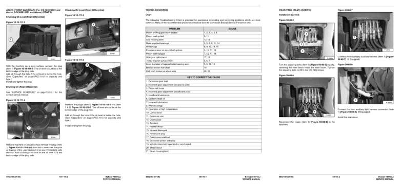
- Specifications, page 44: AXLES (FRONT AND REAR) (For S/N 362812001 and
- Troubleshooting, page 449: TROUBLESHOOTING
- Diagram, page 764: WEAR PADS (REAR) (CONT’D)
Other manuals for this machine
Save 10% on 2 manuals, 15% on 3 or more. Other manuals for the T3571L are listed below. Editions cover different serial number ranges: check the serial coverage and tick only the ones that match your machine.
Added to your cart. View cart
This is a service manual
Here's how it compares to the other manual types.
Service manual
Factory repair procedures and technical information such as specifications, troubleshooting, and wiring and hydraulic diagrams, for the models and systems the manual covers. See What's inside for its topics.
Operator's manual
Safe operation, controls, maintenance schedules, lubrication points, inspections, and basic checks. Repair procedures are in the service manual.
Parts manual
Illustrated diagrams with factory part numbers for identifying components and ordering parts. Repair procedures are in the service manual.
Engine service manuals are sometimes sold separately, since certain machine models were offered with more than one engine option.
What it's used for
Factory manual for in-house farm and construction shop use. Straightforward, complete, and easy to follow. It contains the OEM information dealership service departments and parts counters use to diagnose problems, identify components, and perform maintenance or repairs correctly.
Service shops and owner/operators who repair their own equipment
Identifying correct parts and seeing how assemblies come apart and go back together
Keeping equipment running with less downtime
Factory manual, 1,034 pages
Quantity one is the manual described above.
Fast free USA shipping
Ships in 1 business day.
60-day returns
Free if the mistake is ours. A manual ordered in error must come back unopened in its shrink-wrap; you pay return shipping and a 20% restocking fee applies. Return policy
Binder not included
Manuals over about 300 pages may need a standard 3-ring binder, which you can buy locally to keep the pages organized for shop use.
Other editions and similar models
Questions about model, serial number, engine coverage or contents? Contact us before purchasing and we'll help confirm it's the right manual. Please verify the manual type, machine model, serial number range and engine coverage before purchasing: manuals ordered in error carry a 20% restocking fee (return policy).