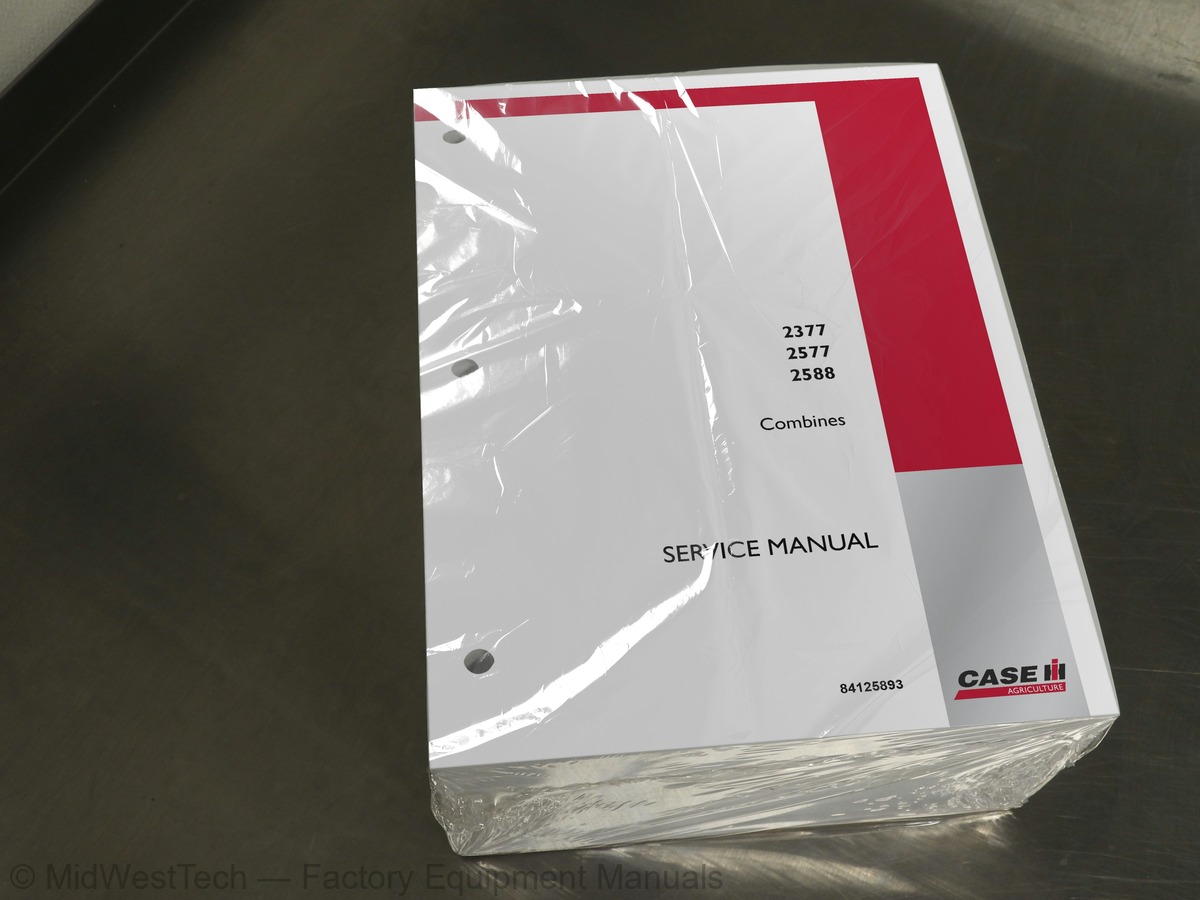
Case 2377, 2577, 2588 Combine Service Manual
2,022 pages · Publication 84125893
Added to your cart. View cart
What's inside
From the manual's own table of contents: 679 topics. See sample pages (PDF, 1106 KB)
- Section 1001 - Standard Torque Specifications Decimal Hardware
- Metric Hardware
- Hydraulic Fittings
- LOCTITE® Product Chart
- Section 1010 - Fluid and Lubricants Engine
- Cooling System
- Fuel System
- Transmission
- Final Drive
- Hydraulic Reservoir
- PTO Housing
- Feeder and Cleaning Fan Gear Case
- Lower Unloader Gear Case
- Feeder Reverse Gear Case
- Rotor Gear Case
- Straw Chopper Gear Case
- Air Conditioning Refrigerant Capacity
- Synthetic Lubricants
- Section 2020 - Engine Removal and Installation Specifications
- Special Torques
- Special Tools
- Engine Removal
- Engine Installation
- Section 4000 - How It Works Combine Ground Points
Show all 679 topics
- Main Valve Assembly Solenoid Functions
- Diode Module Locations
- Cranking and Power Distribution Circuit
- Charging Circuit
- Power Distribution System
- Feedback Module
- Fuel Pump
- Ether Start
- Windshield Wipers
- Right Post Instrumentation Center
- Instrumentation "A" Post Changes
- Grain Scan Monitor
- Shaft Speed Monitor
- Digital Tachometer
- Header Height Display
- Calibration
- Instrument Panel and Warning Lights
- Warning Lights
- Radio Circuit
- Auxiliary Power Circuit
- Air Seat
- Park Brake Circuit
- Dead Engine and/or No Hydraulic Pressure Park Brake Release
- Cleaning Fan Speed Circuit
- Rotor Speed Motor Circuit
- Concave Adjustment Circuit
- Heating Ventilation Air Conditioning System (1999 and earlier)
- Heating Ventilation Air Conditioning System (2000 and later)
- Lighter, Horn and Dome Lights
- Service Lights, Beacon and Back Lighting
- Power Guide Axle and Variable Propulsion Motor
- Header Operation
- Reel Operation
- Diagnostics - Instrumentation and Header Controller
- Feeder and Separator Clutch Controls
- Feeder Reverser Controls
- Header Tilt (Field Tracker®)
- Reel Control Circuit
- Unloader Control Circuit
- Section 4001 - Lighting Circuit Objectives
- Operators Control
- Lighting Circuit Components
- Service Lights and Sieve Light
- Beacon and Back Lighting
- Section 4002 - Wiring Schematics and Troubleshooting, P.I.N. Prior to HAJ0295001 Special Tools
- Fuses and Relay Identification
- Instrumentation and Controls
- Chassis Connector and Component Locations
- Splice Modules
- Electrical Connectors
- Electrical Wire Designations
- Starter and Power Distribution
- Grain Scan Monitor Circuit Testing
- Instrumentation
- Rotor Speed Adjustment Motor Circuit
- Power Guide Axle and Variable Propulsion
- Header Controller
- Feeder and Separator Controls
- Header Tilt
- Reel and Unloader Control
- Machine Ground Locations
- Combine Diagnostics
- Section 4003 - Wiring Schematics and Troubleshooting, P.I.N. HAJ0295001 and After Special Tools
- Fuse Use and Relay Identification
- Relays
- Cab Connector and Component Locations
- Cranking Motor (Starter) and Power Distribution
- Section 4050 - Neutral Start Switch Neutral Start Switch
- Starting Procedure with Auxiliary Batteries
- Section 4235 - Battery Servicing and Testing Battery Condition Check
- Specific Gravity Check
- Capacity (Load) Test
- Three Minute Charge Test
- Testing Battery Cell with Cadmium Probes
- Test Procedure for 12-Volt Battery
- Battery Leakage Test
- Battery Fast Charging
- Battery Charging
- Activating Dry Charged Batteries
- Section 5020 - Steering Hand Pump Special Torques
- Pump Removal
- Pump Disassembly
- Cleaning and Inspection
- Pump Assembly
- Pump Installation
- Section 5030 - Steering Cylinder Special Torques
- Cylinder Removal
- Cylinder Installation
- Combines with Power Guide Wheels
- Cylinder Disassembly
- Cylinder Assembly
- Section 5040 - Steering Axle - all except Power Guide Specifications
- Servicing the Wheel Bearing
- Servicing the Tie Rod
- Toe-In Adjustment
- Spindle Disassembly and Assembly
- Heavy Duty Spindle Disassembly and Assembly
- Servicing Steering Axle Supports
- Axle Pivot Support Installation Positions
- Pivot Support Position Chart
- Servicing Axle Pivots
- Axle Extension Mounting Locations
- Axle Stabilizer
- Axle Shield
- Section 5054 - Steering Axle - Power Guide Special Torques
- Wheel Motor Removal
- Wheel Motor Disassembly
- Wheel Motor Cleaning and Inspection
- Wheel Motor Assembly
- Cross-Sectional Drawing
- Wheel Motor Installation
- Selector Valve Removal
- Selector Valve Disassembly
- Selector Valve Cleaning and Inspection
- Selector Valve Assembly
- Selector Valve Installation
- King Pin Removal
- King Pin Cleaning and Inspection
- King Pin Installation
- Propulsion System Air Removal
- Section 5080 - Steering Priority Valve Specifications
- Valve Removal
- Valve Disassembly
- Valve Cleaning and Inspection
- Valve Assembly
- Valve Installation
- Removing Air from the System
- Section 6000 - Hydrostatic Operation Objectives
- System Operations
- General Information
- System Components
- Reservoir and Filtration
- System Components and Function
- Neutral
- Charge & Shuttle Pressure Relief
- Directional Control Valve
- Forward
- Reverse
- High Pressure Relief System
- Foot-N-Inch Valve
- Internal Pressure Override Control
- Two Speed Hydrostatic Motor Operation
- Test and Adjusting Procedures
- Contamination
- Specifications
- Purging the System
- Adjustment of Propulsion Control
- Pressure Adjustment
- Charge Pressure
- Servo Pressure
- Two Speed Motor Servo Pressure
- Drive Pressure
- Internal Pressure Override Valve
- Drive Alignment
- Drive Hub
- Power Guide Axle
- Electrical System
- System Components & Functions
- Valve Ports
- Wheel Motor Ports
- Valve Low Pressure Shuttle
- Disengaged Position
- Intermediate Position
- Engaged Position
- Flow Divider Spools
- Cam Lobe Motor
- How It Works
- Wheel Motor Flush Circuit
- Motor Case Flush System
- Test Procedures
- Start-Up Procedure Rear Wheel Drive
- Isolating the Problem
- Low Pressure Shuttle Valve
- Solenoid Operation
- Selector Spool Operation
- Wheel Motor Leakage
- Section 6001 - Hydrostatics Neutral Operation
- Forward and Reverse
- Swash Plate Position
- Variable Displacement Pump and Motor
- Hydrostatic Circuit by Progression
- Reservoir
- Heat Exchanger
- Charge Pump and Check Valve
- Inlet Filter
- Manual Displacement Control Valve
- High Pressure Relief Valve
- Shuttle and Charge Pressure Relief Valve
- Internal Pressure Override
- Section 6005 - Hydrostatic Drive System Troubleshooting Transmission Will Not Operate in Either Direction
- Transmission Operates in One Direction
- Sluggish Performance
- System Noisy
- Difficultly in Finding Neutral
- Transmission Operating Hot
- Section 6012 - Hydrostatic Drive System Testing General Test Information
- Hydrostatic Drive Schematic Symbols
- Schematic - Corn/Grain, Single Speed
- Schematic - Corn/Grain, Two Speed
- Schematic - Rice, Two Speed
- Testing the Hydrostatic Drive System
- Section 6015 - Foot-N-Inch Valve Valve Specifications
- Valve Inspection
- Foot-N-Inch Pedal Adjustment
- Section 6017 - Hydraulic Drive Pump Removal and Installation Drive Pump Specifications
- Pump Special Torques
- Pump Removal and Installation
- Section 6018 - Hydrostatic Drive Pump Pump Special Torques
- Shop Equipment Tools
- Pump Identification
- Tools to be Made
- Servicing the Hydrostatic Drive Pump
- Charge Pump
- Power Limiter Valve End Cover
- Control Valve
- Section 6030 - Hydrostatic Drive Motor - Single Speed Special Torques
- Motor Identification
- Drive Motor Disassembly
- Drive Motor Assembly
- Relief Valve Block Disassembly and Assembly
- Section 6031 - Hydrostatic Drive Motor - Two Speed Motor Specifications
- Special Tools to be Made
- Hydrostatic Drive Motor - Two Speed
- Response Valve Disassembly
- Response Valve Assembly
- Block Valve and End Cover Disassembly
- Block Valve and End Cover Assembly
- Servo Cylinder Disassembly
- Servo Cylinder Assembly
- Barrel Disassembly
- Barrel Assembly
- Drive Shaft Seal and Front Cover Disassembly
- Drive Shaft Seal and Front Cover Assembly
- Swash Plate and Trunnion Service
- Section 6035 - Transmission and Hydrostatic Drive Motor Hydrostatic Motor Removal and Installation
- Transmission Removal and Installation
- Gear Shift Control Cable Adjustment
- Section 6040 - Transmission Service Transmission Specifications
- Transmission General Information
- Brake Assembly and Transmission Cover Removal
- Shifter Rails and Shift Fork Removal
- Input Housing and Shaft Removal
- Change Gear Shaft Removal and Disassembly
- Differential Removal and Disassembly
- Differential Pinion Shaft Removal and Disassembly
- Differential Pinion Shaft Assembly and Installation
- Setting Differential Pinion Shaft End Play
- Differential Assembly and Installation
- Measuring Shim Thickness
- Change Gear Shaft Assembly
- Input Housing and Shaft Assembly
- Change Gear Shaft and Input Housing Installation
- Setting Change Gear Shaft End Play
- Measuring Internal Spline Shaft Wear
- Shifter Rails and Shift Fork Assembly
- Transission Cover and Brake Installation
- Cross Sectional Transmission Drawing
- Section 6060 - Final Drives - Removal and Overhaul Final Drives Specifications
- Final Drives Removal
- Final Drives Disassembly
- Final Drives Assembly
- Final Drives Installation
- Section 6061 - Final Drives - Removal and Adjusting Special Torques
- Final Drives General Information
- Extension and Dual Extension
- Final Drives - Small Flange
- Final Drives - Large Flange
- Section 6064 - PTO - How It Works Objectives
- PTO Gear Housing
- Separator Drive Housing
- Variable Rotor Speed Pulley (Driver)
- Three Speed Rotor Drive Gearbox
- Torque Sensing Pulley (Driven Pulley)
- Rotor Belt Alignment
- Rotor Drive Alignment Gauge
- Jackshaft Assembly Alignment
- Variable Rotor Speed Pulley Limit Switches
- Driven Pulley Adjustment
- Rotor Drive Gearbox
- Section 6065 - PTO Removal and Installation Special Torques
- PTO Removal
- PTO Installation
- Section 6071 - Servicing the PTO Housing Specifications
- PTO Housing Disassembly
- PTO Housing Assembly
- PTO Clutch Disassembly
- PTO Clutch Assembly
- Section 7010 - Brake Assemblies - Removal and Overhaul Specifications
- Brake Assemblies Disassembly
- Brake Assemblies Assembly
- Brake Assembly Cross-Section Drawing
- Section 7020 - Master Brake Valve Special Torques
- Brake Valve Removal
- Brake Valve Disassembly
- Brake Valve Assembly
- Brake Valve Installation
- Section 7030 - European Park Brake Special Torques
- Park Brake Valve Removal
- Park Brake Valve Disassembly
- Park Brake Valve Assembly
- Park Brake Valve Installation
- Park Brake Cable Adjustment
- Charging the Accumulator
- Removing Air from the Brake System
- Section 8000 - Hydraulics, How It Works Basic Principles of the System
- Hydraulic Component Locations
- Hydraulic Reservoir and Filters
- Hydraulic Pumps and Drive System
- PFC Piston Pump
- Main Hydraulic Valve Assembly
- Signal Circuits
- Steering Priority Valve
- Main Valve Assembly
- Reel Raise Valve (SV1)
- Control Valve Operation
- Control Valve Orifice Identification
- Unloader Auger Swing Valve
- Reel Fore/Aft Valve
- Field Tracker® Valve
- Header Valve
- Accumulator
- Auxiliary Gear Pump
- Pressure Regulator Valve
- Unloader Auger Clutch Valve
- Park Brake Operation
- Tow Valve
- Feeder Clutch Solenoid
- Reel Drive Valve
- Rotary Air Screen and Separator Drive
- Hydraulic System Testing Procedures
- Low Pressure Standby
- High Pressure Standby
- Steering Signal Relief Pressure
- Reel Drive Relief Pressure
- Regulated Pressure
- Field Tracker® Park Brake Relief
- Auxiliary Gear Pump Flow
- PFC Pump Flow
- Separator and Rotary Air Screen
- Section 8001 - Hydraulic Feeder Reverser Drive Feeder Reverser Controls
- Feeder Reverser
- Feeder Reverser Components
- Feeder Gearbox Components
- Mechanical Components
- Reverser Electrical System
- Reverser Hydraulic System
- Troubleshooting Procedures
- Section 8005 - Accumulator Specifications
- Charging Accumulator with Nitrogen
- Illustration of Nitrogen Charging Accumulator Charging Kit
- Operational Check and Adjustment
- Section 8011 - Hydraulic Schematic and Troubleshooting Hydraulic System Specifications
- Main Valve Assembly Solenoid Locations
- Hydraulic System Troubleshooting
- System Weak or Slow
- PFC Piston Pump Remains on High Pressure Standby
- PFC Pump - No Flow or Low Flow
- PFC Pump Will Not Develop High Pressure Standby
- Header Will Lift and Lower - No Other Main Valve Functions
- Reel Will Not Raise - All Other Main Valve Functions Operate
- Reel Will Not Lower - All Other Main Valve Functions Operate
- Unloader Will Not Swing - All Other Main Valve Functions Operate
- Reel Fore/Aft Not Functioning - All Other Main Valve Functions Operate
- Field Tracker® Not Functioning - All Other Main Valve Functions Operate
- Header Will Not Raise - All Other Main Valve Functions Operate
- Header Will Not Lower
- Header Leaks Down, Exceeding 3/4 Inch/Hour at Cylinders
- Feeder Reverser Will Not Operate - All Other Main Valve Functions Operate
- Reel Will Not Turn
- No Regulated Circuit Functions Work
- One Regulated Pressure Function Will Not Operate
- Steering Effort is High
- Separator Clutch Will Not Engage
- Rotary Air Screen Will Not Rotate
- Testing Procedures
- Low Pressure Standby Test
- Steering Signal Relief Pressure Test
- Reel Drive Standby Pressure Test
- Regulated Pressure Test
- Reel Drive Relief Pressure Test
- Field Tracker®, Park Brake and Feeder Cylinder Thermal Relief Valve Test
- Brake Test - Manual
- Auxiliary Gear Pump Flow Test
- PFC Piston Pump Low Test
- Header Valve Primary Spools
- Unloader Swing and Reel Fore/Aft Valves
- Section 8015 - Pressure Regulator Valve Special Torques
- Section 8020 - Auxiliary Gear Pump and PFC Pump PFC Pump Specifications
- Auxiliary Gear Pump Specifications
- Special Torques - PFC Pump
- Special Torques - Auxiliary Gear Pump
- PFC and Auxiliary Gear Pump Removal
- Auxiliary Gear Pump Disassembly
- PFC Pump Disassembly
- Auxiliary Gear Pump Assembly
- PFC Pump Assembly
- PFC and Auxiliary Gear Pump Installation
- Section 8030 - Hydraulic Valve Stack Specifications
- Main Hydraulic Valve Stack
- Removal
- Main Valve Stack
- Field Tracker® and Reel Fore/Aft Valve
- Unloading Auger Swing and Reel Raise/Lower Valve
- Disassembly
- Field Tracker Valve
- Unloader Swing Valve
- Reel Raise/Lower Valve
- Assembly
- Installation
- Field Tracker and Reel Fore/Aft Valve
- Section 8040 - Park Brake and Feeder Clutch Valves Special Torques
- Park Brake and Feeder Clutch Valve Removal
- Valve Adjustment
- Section 8050 - Separator Clutch Valves Special Torques
- Separator Clutch Valve Removal
- Unloader Auger Clutch Valve Removal
- Separator Clutch Valve Installation
- Unloader Auger Clutch Valve Installation
- Section 8051 - Separator Drive Test and Troubleshooting General Troubleshooting
- Separator Clutch Control Valve Test
- Separator Drive Pressure/Flow Testing
- Separator Pressure Flow Test Diagram
- Separator Drive Accumulator Test
- Separator Drive Assembly Oil Flush Procedure
- Section 8055 - Rotary Air Screen and Power-Clean Evacuation System How It Works
- Rotary Air Screen Hydraulic Motor
- Power-Clean Hydraulic Motor
- Rotary Air Screen Pump
- Section 8060 - Hydraulic Cylinders Special Torques
- Feeder Clutch Cylinder Removal and Installation
- Separator and Feeder Clutch Disassembly and Assembly
- Unloader Tube Swing Cylinder Removal and Installation
- Unloader Tube Swing Cylinder Disassembly and Assembly
- Header Lift Cylinder Removal and Installation
- Header Lift Cylinder Disassembly and Assembly
- Reel Lift Cylinder Removal and Installation
- Bat Reel Lift Master Cylinder Disassembly and Assembly
- Bat Reel Lift Slave Cylinder Disassembly and Assembly
- Pickup Reel Lift Master Cylinder Disassembly and Assembly
- Pickup Reel Lift Slave Cylinder Disassembly and Assembly
- Reel Fore/Aft Cylinder Removal and Installation
- Reel Fore/Aft Cylinder Disassembly and Assembly
- Section 8080 - Reel Drive Control Valve Valve Specifications
- Drive Valve Removal
- Drive Valve Disassembly
- Drive Valve Assembly
- Drive Valve Installation
- Section 8090 - Reel Drive Motor Motor Specifications
- Reel Drive Motor Removal
- Motor Installation
- Section 9010 - Air Conditioning Troubleshooting Safety Procedures
- Access the Evaporator/Heater Assembly
- Automatic Temperature Control (ATC)
- Automatic Temperature Control Systems
- Temperature Range
- Smart Pressure Switch Cycling System
- Air Conditioning Operation
- ATC Wiring Schematic
- ATC Troubleshooting
- ATC Electrical Troubleshooting
- ATC Fault Codes
- High/Low Pressure Switch Circuit Test
- Blower Potentiometer and Circuit Test
- Temperature Potentiometer Circuit Test
- Cab Temperature Sensor Circuit Test
- Evaporator Temp. Sensor Circuit Test
- ATC Controller Power Supply and Ground Test
- Blower Motor Power Supply/Ground Test
- Clutch Relay Power Supply/Ground Test
- Heater Control Valve Power Supply and Ground Test
- ATC Switch and Circuit Test
- PWM Module Power Supply Circuit Test
- LCD Display and Circuit Test
- Pressurizer Blower Motor Circuit Test
- External Compressor Check
- Compressor, Mount Brackets, Fan Belts
- Compressor Clutch
- Pulley and Belt Alignment
- Operational Modes
- Keyed Power - Automatic Mode
- Defog/Defrost Mode
- Blower and Temperature Control
- Motor
- Speed, Temp. Control, LCD Display
- Controller Initialization
- ATC Control Switch
- ATC Controller
- Low and High Pressure Switches
- Cab Temperature Check
- Air Louvers
- Air Conditioning Hose Check
- Lower Louver Temperature
- Compressor Hoses
- Leak Finding Check
- Heater Hoses
- Heater Control Valve
- Evaporator and Plenum Check
- Cab, Evaporator Temperature Sensors
- Cab Pressurizer Blower
- ATC Component Locations
- Section 9020 - Air Conditioning System Service - System R-134a Specifications
- Safety Procedures
- Air Conditioning System Refrigerant Recovery
- Air Conditioning Compressor
- Oil Level Check or Adjustment
- Injection Method
- Dipstick Method
- Compressor Removal
- Compressor Installation
- Compressor Belt Installation and Adjustment
- A/C System Evacuation and Recharging
- Air Conditioning Compressor Clutch
- Clutch Removal
- Exploded View Illustration of Clutch
- Compressor Clutch Replacement
- Thermal Expansion Valve Testing
- Thermal Expansion Valve Replacement
- ATC Components
- Condenser, Receiver-Drier and Tubes
- Evaporator Temp. Sensor Installation
- Blower and Evaporator Illustration
- Heater and Evaporator Core
- Accessing the Air Conditioning Unit
- Core Removal
- Core Installation
- ATC Controller and PWM Module Replacement
- Cab Recirculation Air Filter Service
- Cab Intake Air Filter Service
- Cab Pressurization Test
- Section 9030 - Air Conditioning System and Compressor Specifications
- A/C System Refrigerant Recovery
- Section 9040 - Air Conditioning Components Specifications
- Compressor Belt Check and Adjustment
- Compressor Oil Level Check
- Compressor Clutch Disassembly
- Compressor Clutch Assembly
- Expansion Valve Testing
- Evaporator and Expansion Valve
- Core Temperature Sensor
- Heater and Evaporator Core Removal
- Heater and Evaporator Core Installation
- Removing Air from the Cooling System
- A/C Control Module Replacing
- Operator Cab Intake Air Filter Removal
- Operator Cab Intake Air Filter Service
- Section 9100 - Auto Greasing System How the System Works
- Manual Start Switch and System Indicator Lamps
- Timer Operation
- Filling Reservoir
- Hours
- Reservoir Manual Fill
- Splicing Broken Lubricating Lines
- Greasing System
- Metering Valve
- Divider Valve
- Check List
- Daily Walk-Around Inspection
- Troubleshooting
- Section 9101 - Separator Drive Jackshaft Specifications
- Jackshaft Service Procedure
- Separator Belt Removal
- Jackshaft Removal
- Jackshaft Disassembly
- Jackshaft Assembly
- Jackshaft Installation
- Separator Belt Installation and Adjustment
- Separator Belt Tightener Pulley Removal
- Separator Belt Tightener Disassembly
- Separator Belt Tightener Assembly
- Separator Belt Tightener Installation
- Section 9102 - Rotor Drive Specifications
- Torque Sensing Unit Removal
- Servicing the Torque Sensing Unit
- Bushing Replacement
- Illustration of Torque Sensing Unit
- Torque Sensing Unit Installation
- Section 9103 - Rotor Gearbox General Safety Information
- Removal Procedure
- Gearbox Disassembly
- Input Shaft Service
- Output Shaft Service
- Gearbox Assembly
- Checking End Play and Rolling Torque
- Gearbox Installation
- Section 9104 - Rotor Specifications
- Feeder Housing Removal
- Rotor Removal
- Rotor Inspection and Repair
- Rotor Installation
- Feeder Housing Installation
- Belt Installation and Adjustment
- Replacing the Rotor Front Bearing Without Removing the Rotor
- Section 9105 - Rotor Drive Belt Rotor Drive Belt Removal
- Belt Installation
- Rotor Belt Adjustment
- Rotor Drive Belt and Separator Jackshaft Assembly Alignment
- Jackshaft Limit Switch Adjustment
- Section 9106 - Feeder and Cleaning Fan Gearbox Specifications
- Feeder and Cleaning Fan Gearbox
- Section 9107 - Cleaning Fan Drive Fan Drive Specifications
- Fan Drive Special Torques
- Fan Jackshaft Removal and Disassembly
- Drive Pulley Removal and Disassembly
- Fan Speed Control Motor Removal and Disassembly
- Fan Speed Control Motor Assembly and Installation
- Drive Pulley Assembly and Installation
- Fan Jackshaft Assembly and Installation
- Section 9109 - Elevator Drive Jackshaft Elevator Drive Jackshaft Specifications
- Elevator Drive Jackshaft Special Torques
- Removal of Elevator Drive Jackshaft
- Servicing the Elevator Drive Jackshaft
- Installation of Elevator Drive Jackshaft
- Section 9110 - Inclined Delivery Auger Delivery Auger Special Torques
- Delivery Auger Special Tools
- Auger and Sprocket Housing Removal
- Auger Sprocket Housing Disassembly
- Auger Sprocket Housing Assembly
- Auger and Sprocket Housing Installation
- Section 9111 - Discharge Beater Beater Removal
- Beater Installation
- Section 9113 - Straw Spreader Drive Straw Spreader Drive Specifications
- Replacing Spreader Drive Belt
- Adjusting the Bevel Gear End Play
- Spreader Blade Timing and Sensor Gap Check
- Section 9115 - Header Knife Drive Knife Drive Specifications
- Knife Drive Special Torques
- Removal of header Knife Drive Box
- Servicing the Knife Drive Box
- Installation of Knife Drive Box
- Section 9116 - Tailing Monitor Tailing Monitor Components
- Tailing Monitor Circuit Diagnostics
- Section 9117 - Unloader Auger System Unloader Specifications
- Unloader Special Torques
- Removal of Lower Unloader Gearbox
- Servicing the Lower Unloader Gearbox
- Installation of Lower Unloader Gearbox
- Removal of Upper Unloader Gearbox
- Servicing the Upper Unloader Gearbox
- Installation of Upper Unloader Gearbox
- Adjusting the Unloader Tube Limit Switches
- Horizontal Unloading Auger
- Grain Tank Auger Cover Adjustment
- Section 9120 - Field Tracker Tilt Cylinder and Wear Plate Removal and Installation
- Tilt Cylinder Disassembly and Assembly
- Section 9121 - Cross-Flow™ Fan Cross-Flow Specifications
- Fan Special Torques
- Fan Removal
- Fan Installation
- Section 9125 - Straw Chopper Gearbox Chopper Gearbox specifications
- Chopper Gearbox Special Torques
- Gearbox Removal
- Servicing Chopper Gearbox Disassembly
- Servicing Chopper Gearbox Assembly
- Section 9128 - Adjustable Concaves Replacing the Adjustable Concave Control Motor
- Testing the Position Sensing Potentiometer
Inside this manual
Real pages from this service manual (2,022 pages). Open the sample pages (PDF, 1104 KB)
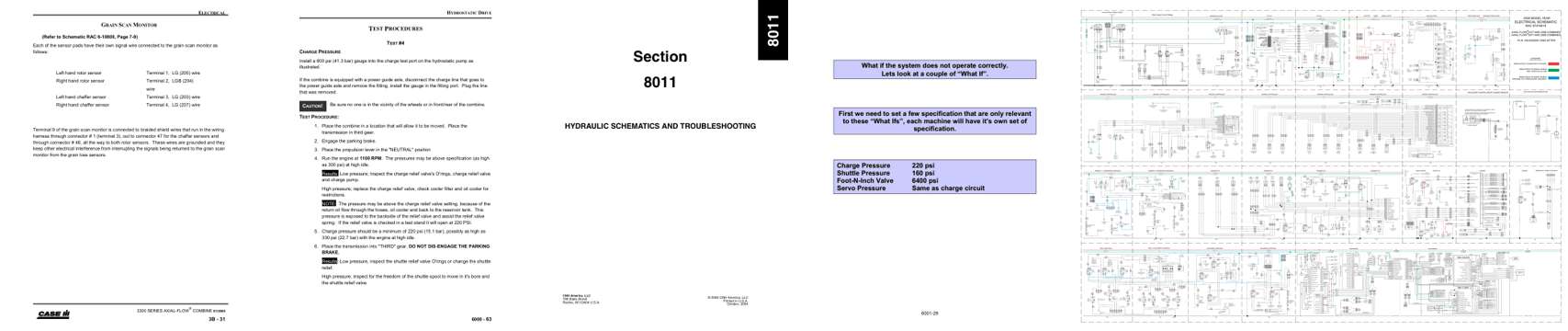
- Diagram, page 83: ELECTRICAL
- Specifications, page 765: HYDROSTATIC DRIVE
- Troubleshooting, page 1,292: Section
- Color page: What if the system does not operate correctly.
- Foldout diagram (color): CHASSIS GROUND
Other manuals for this machine
Save 10% on 2 manuals, 15% on 3 or more. Other manuals for the 2588 are listed below. Editions cover different serial number ranges: check the serial coverage and tick only the ones that match your machine.
Added to your cart. View cart
This is a service manual
Here's how it compares to the other manual types.
Service manual
Factory repair procedures and technical information such as specifications, troubleshooting, and wiring and hydraulic diagrams, for the models and systems the manual covers. See What's inside for its topics.
Operator's manual
Safe operation, controls, maintenance schedules, lubrication points, inspections, and basic checks. Repair procedures are in the service manual.
Parts manual
Illustrated diagrams with factory part numbers for identifying components and ordering parts. Repair procedures are in the service manual.
Engine service manuals are sometimes sold separately, since certain machine models were offered with more than one engine option.
What it's used for
Factory manual for in-house farm and construction shop use. Straightforward, complete, and easy to follow. It contains the OEM information dealership service departments and parts counters use to diagnose problems, identify components, and perform maintenance or repairs correctly.
Service shops and owner/operators who repair their own equipment
Identifying correct parts and seeing how assemblies come apart and go back together
Keeping equipment running with less downtime
Factory manual, 2,022 pages
Quantity one is the manual described above.
Fast free USA shipping
Ships in 1 business day.
60-day returns
Free if the mistake is ours. A manual ordered in error must come back unopened in its shrink-wrap; you pay return shipping and a 20% restocking fee applies. Return policy
Binder not included
Manuals over about 300 pages may need a standard 3-ring binder, which you can buy locally to keep the pages organized for shop use.
Other editions and similar models
Questions about model, serial number, engine coverage or contents? Contact us before purchasing and we'll help confirm it's the right manual. Please verify the manual type, machine model, serial number range and engine coverage before purchasing: manuals ordered in error carry a 20% restocking fee (return policy).