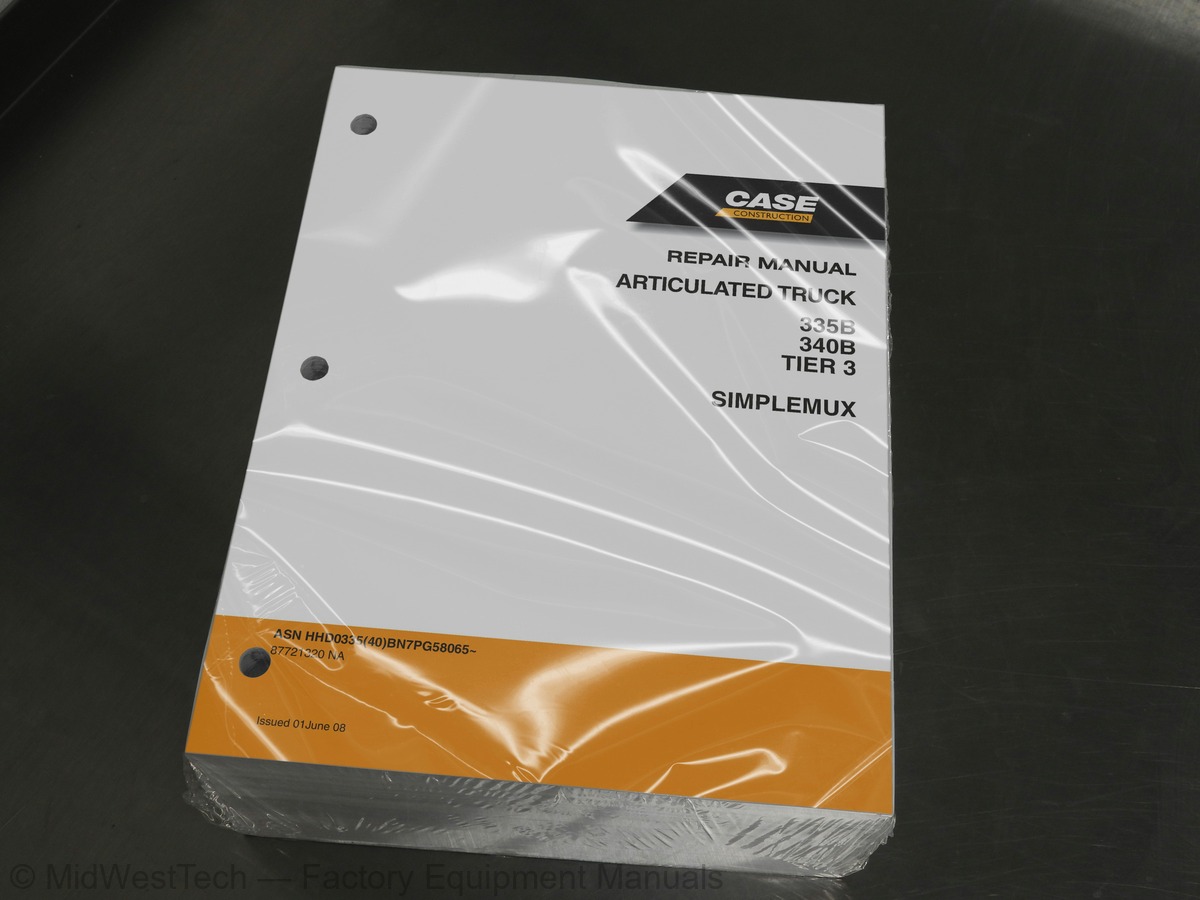
Case 335B, 340B Tier 3 Simplemux Articulated Dump Truck Service Manual
1,460 pages · Publication 87721320
Added to your cart. View cart
- Models
- 335B, 340B Tier 3 Simplemux
- Manual type
- Service Manual
- Pages
- 1,460
- Publication
- 87721320
- Condition
- Brand new
What's inside
From the manual's own table of contents: 10 sections, 520 entries. See sample pages (PDF, 718 KB)
General8 topics
- GENERAL
- ENGINES
- ELECTRICAL
- STEERING
- POWER TRAIN
- BRAKES
- HYDRAULICS
- MOUNTED EQUIPMENT
SECTION 1 - GENERAL91 topics
- CONDITIONS OF USE
- INFORMATION ON THIS HANDBOOK
- Definitions
- Symbols
- Purpose of this handbook
- To whom this handbook is addressed
- Safekeeping of this handbook
- Updates to this handbook
- Units of measure
- SCHEDULED USE
- VEHICLE DRIVERS
- WASTE DISPOSAL
- WARRANTY AND LIABILITY OF THE MANUFACTURER
- Warranty conditions
- Liability
- SERVICE
- After sales service
- Spare parts
- GENERAL OPERATION RULES
- Pre-disassembly preparation
- During disassembly
- Disconnecting hydraulic lines
- After disassembly
- During assembly
- Screw and nut tightening
- Connecting hydraulic lines
- Interchangeable parts
- Welding on the chassis
- INTRODUCTION
- Safety information and symbols
- General instructions
- preventing fires
- ROLLOVER ACCIDENTS
- Prevention
- What to do if the vehicle rolls over
- Structure of the cab
- instructions for use
- Starting and stopping
- Driving the vehicle
- Working the vehicle
- Towing the vehicle
- Replacing the wheel
- MAINTENANCE
- Electrical power disconnection
- Disconnection of the emergency electric power supply
- Emergency switch
- VEHICLE COMPOSITION
- DIMENSIONS (EMPTY VEHICLE)
- DIMENSIONS WITH BODY RAISED
- WEIGHTS
- CENTER OF GRAVITY (HORIZONTAL POSITION)
- PERFORMANCE
- PERFORMANCE ALIGNMENT CHART
- Using the alignment chart
- MAIN TECHNICAL SPECIFICATIONS
- Chassis number
- CASE PIN plate
- POSITION OF IDENTIFICATION DATA ON MAIN GROUPS
- Chassis
- Engine
- Automatic transmission
- Drive axles
- Dump cylinders
- Steering cylinders
- Front suspension cylinders
- Front drive axle
- Intermediate and rear drive axles
- Suspension
- Wheels and tyres
- Hydraulic system
- Electrical system
- Drive cab
- Body
- LIST OF BULBS
- CAPACITIES
- TYRE PRESSURE TABLE
- ANTIFREEZE CONCENTRATION IN ENGINE COOLANT
- ANTIFREEZE CONCENTRATION IN WINDSHIELD WASHER FLUID
- BATTERY ELECTROLYTE DENSITY TABLE
- TIGHTENING TORQUE
- PLATES APPLIED TO THE VEHICLE
- STANDARD TIGHTENING TORQUES
- Screws and nuts with metric thread
- MEASURES (INTERNATIONAL SYSTEM)
- MULTIPLEX SYSTEM FAULT CODES
- FAULT CHECK USING THE DISPLAY
- MULTIPLEX SYSTEM FAULT CODES LIST - SOFTWARE VERSION 3.3.0.0
- ENGINE FAULT CODES
- ENGINE CONTROL FAULT CODES LIST
- MULTIPLEX SYSTEM FAULT CODES LIST
- DIAGNOSTIC CONNECTOR PIN-OUT
SECTION 2 - ENGINE43 topics
- WALK AROUND
- ELECTRONIC SYSTEM CONTROL
- Electrical and electronic components
- Component location on engine right-hand side
- Component location on engine left-hand side
- FEEDING
- FUEL SUPPLY DIAGRAM
- Fuel Pump
- Injector-pump
- Pumping element
- Nozzle
- Solenoid valve
- Fuel Supply Circuit Diagram
- ENGINE AIR INTAKE SYSTEM
- VARIABLE GEOMETRY TURBINE (VGT)
- ACTUATOR ADJUSTMENT
- Operating principle
- VGT CONTROL SOLENOID VALVE
- VGT Electromagnetic Valve
- ENGINE EXHAUST SYSTEM
- ENGINE BRAKE
- EARLY CLOSING SYSTEM FOR THE INTAKE VALVES
- COOLING
- Main circuit engine cooling circuit
- MAIN CIRCUIT ENGINE COOLING CIRCUIT (335B & 340B SIMPLEMUX)
- Thermostat operation - engine cooling system
- LUBRICATION
- Lubrication system outline
- Lubrication system outline - Detail A
- Oil pump
- Additional oil pump
- Oil pressure regulator valve
- Heat exchanger
- Thermostatic valve
- By-pass valve
- Engine oil filters
- TECHNICAL SPECIFICATION
- GENERAL CHARACTERISTICS
- TRANSVERSAL SECTION
- LONGITUDINAL SECTION
- ASSEMBLY CLEARANCE DATA
- TIGHTENING TORQUES
- TIGHTENING ORDER OF GEARBOX TO ENGINE BLOCK FASTENING SCREWS
SECTION 4 - ELECTRICAL41 topics
- MULTIPLEX SYSTEM OVERVIEW
- Conventional control
- MULTIPLEX system
- CAN LINE
- Static efficiency tests
- Measurement values
- MULTIPLEX SYSTEM GENERAL DIAGRAM
- BULKHEAD CONNECTORS
- WHITE feedthrough connector cabling-side PIN-OUT
- BROWN feedthrough connector cabling-side PIN-OUT
- YELLOW feedthrough connector cabling-side PIN-OUT
- GREEN feedthrough connector cabling-side PIN-OUT
- CAN OPEN LINE
- BODY COMPUTER SYSTEM COMPONENTS
- CLUSTER
- CLUSTER control unit PIN-OUT
- I/O MODE
- I/O MODE control unit PIN-OUT - connector J2
- I/O MODE control unit PIN-OUT - connector J3
- MIDAC
- MIDAC control unit PIN-OUT
- LOCATION OF SENSORS AND ACTUATORS
- CAN J1939 LINE
- EDC ENGINE CONTROL UNIT
- A” Electro-injectors connector
- B” chassis connector
- C” sensors connector
- TRANSMISSION CONTROL UNIT (TCU)
- Transmission control unit pin-out
- ELECTRICAL SUPPLY
- Batteries
- GROUND POINTS
- RELAYS AND FUSES INTERCONNECTION CONTROL UNIT
- RELAYS AND FUSES
- Relays
- Relays, resistors and diodes supplementary
- Optional equipment fuses (breakdown)
- Fuse overview
- Supplementary fuses
- Fusebox component wiring
- TOPOGRAPHIC DIAGRAMS
SECTION 5 - HYDRAULIC SYSTEM11 topics
- WHEELS
- DESCRIPTION
- SPECIFICATIONS AND DATA
- 335B (Dry disc brakes models only)
- 340B (Wet brakes models only)
- REPLACING A COMPLETE WHEEL
- Disassembly
- Fitting
- TYRE–RIM DISASSEMBLY–ASSEMBLY
- Cleaning of the wheel parts
- Reassembly
CHAPTER 2 - STEERING AND DUMPING36 topics
- STEERING AND DUMPING SYSTEM – DESCRIPTION
- Main components
- Function
- Main components of the steering – dumping system
- HYDRAULIC DIAGRAM
- Steering – dumping hydraulic system (see next page)
- Steering – dumping hydraulic diagram
- Dumping valve
- OPERATION
- TOPOGRAPHICAL DIAGRAMS
- Topographic diagram of the front chassis
- Topographic diagram of the rear chassis
- Changing the fluid
- Replacing the pressurised brake actuator filter
- Cleaning the (suction) filter
- Replacing the steering/dumping pressurised filter
- Cleaning inside the filter (suction)
- STEERING–DUMPING SYSTEM TEST PROCEDURES
- Hydraulic system air bleeding
- Hydraulic system pressure discharge with engine off
- Steering–dumping hydraulic system pressures check
- Prescribed pressure values
- Dumping and steering valves
- DIAGNOSTICS
- Prescribed pressare values
- The steering valve does not work (the vehicle does not turn when operating the steering wheel)
- The body does not tip
- The body raises slowly even with the engine at maximum speed
- The body does not lower
- MAIN PUMP REMOVAL – REPLACEMENT
- Removal
- Replacement
- DUMPING VALVE REMOVAL – REPLACEMENT
- DUMPING CYLINDER REMOVAL – REPLACEMENT
- STEERING VALVE REMOVAL – REPLACEMENT
- STEERING CYLINDER REMOVAL – REPLACEMENT
SECTION 5 - STEERING5 topics
- EMERGENCY STEERING SYSTEM
- Emergency steering hydraulic diagram
- INSPECTION PROCEDURES
- Check of the emergency steering pump control efficiency
- EMERGENCY STEERING PUMP REMOVAL–REPLACEMENT
SECTION 6 - POWER TRAIN99 topics
- AUTOMATIC TRANSMISSION CROSS-SECTION VIEW
- AUTOMATIC TRANSMISSION EXTERNAL PIPE ARRANGEMENT VIEW
- TRANSMISSION SPEED SENSORS
- Speed sensor location
- Speed sensor setting
- FUNDAMENTAL COMPONENTS
- Torque converter
- Lock–up clutch
- Clutches
- Hydrodynamic brake (retarder)
- Central differential lock
- 1st forward gear: ratio 1:5.350
- 2nd forward gear: ratio 1:3.446
- 3rd forward gear: ratio 1:2.207
- 4th forward gear: ratio 1:1.421
- 5th forward gear: ratio 1:0.970
- 6th forward gear: ratio 1:0.625
- 1st reverse gear: ratio 1:5.350
- 2nd reverse gear: ratio 1: 2.207
- 3rd reverse gear: ratio 1:0.970
- FRONT DIFFERENTIAL FITTING
- TRANSMISSION OIL COOLING SYSTEM
- Automatic transmission oil circulation system diagram
- TRANSMISSION CONTROL SYSTEM COMPONENTS - TYPE B
- Connector key
- TECHNICAL DATA
- CASE SPECIAL TOOLS
- Oil level check
- Breather
- Oil change
- Oil filter change
- AEB procedure
- Display – meaning of AEB procedure messages
- TRANSMISSION HYDRAULIC CONTROL DIAGRAM
- Position of the pressure and temperature measuring points
- Electro – hydraulic unit
- SERVICE INSTRUCTIONS
- Pressures check pipes installation
- Pressure measuring ports
- DISC BRAKE VERSION - DESCRIPTION
- First reduction: bevel pair
- Second reduction: hub and planetary train
- Brake caliper
- Brake disc and caliper
- Bevel gear (first reduction)
- Planetary train and hub (second reduction)
- TOOLS
- Replacement of the brake pads
- Breaking-in of the pads
- FRONT DIFFERENTIAL
- Checking oil level
- Changing the oil
- FRONT HUBS
- FRONT HUB REMOVAL-REFIT
- Installation
- BRAKE CALIPER REMOVAL-INSTALLATION
- PLANETARY REDUCER OVERHAUL
- Planetary reduction gear seals and thread-stops application and bearings diagram
- Inspection of the dismantled parts
- FRONT DIFFERENTIAL OVERHAUL
- Inspection of the disassembled parts
- Diagram of bearings and the application of thread-locks and distributor and differential seals
- Diagram of the self-locking differential assembly
- BRAKE CALIPER OVERHAUL
- BRAKE DISC OVERHAUL
- WET BRAKE VERSION - DESCRIPTION
- Splitter Unit
- First reduction: bevel gear pair
- Splitter unit and bevel gear pair (first reduction)
- EQUIPMENT
- INTERMEDIATE AXLE REMOVAL-REFIT
- Removal of the supports
- DIFFERENTIAL AND DISTRIBUTOR OVERHAUL
- Diagram of bearings and the application of thread- locks and distributor and differential seals
- Braking assembly
- Breaking system connections
- REAR AXLE REMOVAL-REFIT
- Diagram of bearings and the application of thread- locks and differential and countershaft seals
- Automatic clearance recovery device
- SPECIFICATION AND DATA
- Hub and planetary gear (second reduction)
- Central splitter
- Axle splitter
- Front axle
- Propeller shafts
- Driveline (Disc brakes models only)
- Driveline (Wet brakes models only)
- Parking brake unit
- TIGHTENING TORQUES (DISC BRAKES MODELS ONLY)
- TIGHTENING TORQUES (WET BRAKES MODELS ONLY)
- Parking brake caliper release
- Replacement of the parking brake pads
- PROPELLER SHAFT REMOVAL– REPLACEMENT
- DETACHMENT–INSTALLATION OF THE PARKING BRAKE DISC AND CALIPER
- Removal of the caliper
- REMOVAL – INSTALLATION OF THE CENTRAL SUPPORT
- CENTRAL BEARING OVERHAUL
- Dismantling
- Assembly
SECTION 7 - BRAKES33 topics
- BRAKING SYSTEM
- Main components of the braking system
- Service and parking brakes – location
- TOPOGRAPHIC DIAGRAMS (VERSION WITHOUT DUMPING BRAKE)
- TOPOGRAPHIC DIAGRAMS (VERSION WITH DUMPING BRAKE)
- BRAKING SYSTEM TEST PROCEDURES
- BRAKE PUMPREMOVAL–REPLACEMENT
- HYDRAULIC ACCUMULATOR REMOVAL–REPLACEMENT
- Braking system hydraulic diagram – version without dumping brake
- Braking system hydraulic diagram – version with dumping brake
- Braking hydraulic system air bleeding
- Braking system pressure discharge with engine off
- Braking hydraulic system pressures check
- Braking hydraulic system pressures adjustment
- Brake pedal position adjustment
- BRAKE PUMP REMOVAL–REPLACEMENT
- BRAKE PEDAL VALVE REMOVAL–REPLACEMENT
- BRAKES COOLING SYSTEM
- Main components brake cooling system
- Brake cooling system hydraulic diagram
- A. OIL TANK
- B. BRAKE COOLING MOTOR/PUMP GROUP
- C. BRAKE COOLING SYSTEM WATER–OIL HEAT EXCHANGER
- D. BRAKE COOLING SYSTEM FILTER
- E. FRONT AXLE BRAKE COOLING GROUP
- F. REAR CHASSIS CONNECTION PLATE
- G. INTERMEDIATE AXLE BRAKE COOLING GROUP
- H. REAR AXLE BRAKE COOLING GROUP
- Replacing the pressurised filter
- Cleaning the internal (suction) filter
- BRAKE COOLING SYSTEM TEST PROCEDURES
- BRAKE COOLING SYSTEM TROUBLESHOOTING
- BRAKE COOLING CIRCUIT PUMP–MOTOR REMOVAL–REPLACEMENT
SECTION 8 - HYDRAULIC SYSTEM21 topics
- DESCRIPTION DRY DISC BRAKES MODELS
- General diagram
- DESCRIPTION WET BRAKES MODELS
- Location of the tanks, pumps and exchangers
- HYDRAULIC SYSTEM PRESSURE TEST POINTS – DRY DISC BRAKES MODELS
- Steering–dumping–fan system
- Brakes actuation system
- Table of nominal hydraulic system pressures - disk brakes models
- HYDRAULIC SYSTEM PRESSURE TEST POINTS – WET BRAKES MODELS (340B)
- Brake actuation system – brake cooling system
- Table of nominal hydraulic system pressures - wet brakes models
- Main pump (Rotary Piston Pump)
- Brake pump
- Emergency steering pump
- Dumping distributor
- Steering valve
- Back–pressure valve
- Accumulators – disk brakes
- Accumulators – wet brakes
- Fan drive
- Cartridge filters
SECTION 9 - MOUNTED EQUIPMENT122 topics
- Front suspension
- Hydro–pneumatic cylinder – description
- Hydro–pneumatic cylinder – view
- Rear suspension
- Equipment connection diagram
- Checking suspension cylinder height
- Checking suspension element pressure
- Inflating the suspension elements
- Deflating the suspension element pressure
- Changing the suspension fluid element
- DISASSEMBLY–REASSEMBLY OF THE AXLE SHAFT PROTECTIONS
- FRONT SUSPENSION REMOVAL–REPLACEMENT
- Half shaft removal
- Detachment of the hubs
- FRONT SUSPENSION CYLINDER REMOVAL–REPLACEMENT
- REPLACEMENT OF THE FRONT SUSPENSION BALL JOINT
- REAR SUSPENSION REMOVAL–REPLACEMENT
- DISASSEMBLY–REASSEMBLY OF THE REAR SUSPENSION CENTRAL BUSHINGS
- REMOVAL–REPLACEMENT OF THE REAR SUSPENSION STABILIZER BARS
- REMOVAL–REPLACEMENT OF THE REAR SUSPENSION BUSHINGS
- Elastic articulation bushes on the axles
- Flexible coupling
- SUSPENSION CYLINDER OVERHAUL
- PNEUMATIC DIAGRAM
- Retarder pressure fitting location (n. 25 on the diagram)
- COMPONENTS LOCATION PNEUMATIC SYSTEM
- DIAGNOSTIC
- Compressor
- DRIER
- Parking brake distributor (335 & 340 Tier 3 only)
- Checks
- MAIN COMPONENTS PNEUMATIC SYSTEM COMPRESSOR
- Single–chamber air drier
- Air intake valve
- PRESSURE RELIEF VALVE
- Parking brake control
- Manual condensation discharge valve
- MANUAL GREASING
- Lubrication system checks
- Lay-out system
- AUTOMATIC GREASE SYSTEM
- CALIBRATE GREASING
- SET TIME GREASING
- FORCE GREASING START
- CALIB. TIME GREASING
- Lay-out system front chassis
- Lay-out system rear chassis
- Restoring grease dispenser functionality
- Restore operation of the automatic greasing control unit after disassembly/draining
- Checks of the lubrication control unit components
- Repair of the lubrication system piping
- DISTRIBUTION DIVIDER
- Quantity of lubricant supplied (A)
- Indicators (B)
- AIR–CONDITIONING SYSTEM
- Functional principle
- Functional outline
- Component layout
- Climate control system
- Climate control system air vents
- ELECTRICAL CIRCUIT DIAGRAM
- Air-conditioning system electrical circuit diagram
- Fan not working
- Fan works but with poor air–flow
- Normal function but poor air cooling
- Compressor not functioning or functioning poorly
- Diagnosis by pressure measurement
- Low pressure circuit – insufficient pressure
- Low pressure circuit – excessive pressure
- High pressure circuit – insufficient pressure
- High pressure circuit - excessive pressure
- System charge check
- Cleaning/replacing passenger air cleaner
- Cleaning condenser
- GENERAL SERVICING
- Usable fluids
- Draining R134a fluid
- Works on system piping
- Compressor lubricant
- SYSTEM DRAINING AND RECHARGING PROCEDURES
- R134A REFRIGERANT RECHARGING AND RECOVERY STATION (99305146)
- CONTROL PANEL
- CHARGE CYLINDER AND OIL TANK
- SAFETY STANDARDS
- OPERATIONS FLOW DIAGRAM
- RECOVERING REFRIGERANT FROM SYSTEM ON VEHICLE
- CREATING VACUUM IN SYSTEM
- RESTORING SYSTEM OIL
- CHARGING THE SYSTEM WITH REFRIGERANT
- CHECKING SYSTEM PRESSURES
- OPERATIONS PRIOR TO REMOVING STATION FROM SYSTEM
- LEAKDETECTORFOR AIRCONDITIONING SYSTEMS WITH HFC R134A (99305147)
- ENGINE BONNET TIPPING HYDRAULIC SYSTEM
- CAB TIPPING HYDRAULIC SYSTEM
- Cab tipping hydraulic system components location
- Cab tipping hydraulic system diagram
- CAB REMOVAL–REPLACEMENT
- CAB COMPONENTS REMOVAL–REPLACEMENT
- BONNET
- LOWER COVERS
- SIDE COVERS
- SIDE PANELS
- BONNET TILTING CYLINDER
- CAB TILTING CYLINDER
- Front chassis
- Rear chassis
- Articulation joint (Figure 4)
- Interface flange
- ARTICULATION JOINT REMOVAL-REPLACEMENT
- Articulation ball joint pre-load adjustment
- Reattachment
- TESTS AND CHECKS
- Chassis lateral bending check
- Finding chassis bending up and down
- Vertical bending admitted: b=1 mm (0.04 in)
- Finding chassis twist
- Bending up and down admitted on chassis: c=1mm (0.04 in)
- REPAIR OPERATIONS
- Precautions
- Straightening the chassis
- BODY DETACHMENT–REASSEMBLY
- Adjustment of the body position proximity sensors
Inside this manual
Real pages from this service manual (1,460 pages). Open the sample pages (PDF, 717 KB)

- Troubleshooting, page 149: Issued 01-2008
- Specifications, page 1,117: CHAPTER 4 - REAR AXLE
- Diagram, page 1,271: CHAPTER 3 - 340B BRAKE COOLING SYSTEM, WET BRAKE MODELS
- Color page, page 636: Issued 06-2008
- Color page, page 435: Issued 06-2008
- Foldout diagram, page 482: Issued 06-2008
Other manuals for this machine
Save 10% on 2 manuals, 15% on 3 or more. Other manuals for the 335B are listed below. Editions cover different serial number ranges: check the serial coverage and tick only the ones that match your machine.
Added to your cart. View cart
This is a service manual
Here's how it compares to the other manual types.
Service manual
Factory repair procedures and technical information such as specifications, troubleshooting, and wiring and hydraulic diagrams, for the models and systems the manual covers. See What's inside for its topics.
Operator's manual
Safe operation, controls, maintenance schedules, lubrication points, inspections, and basic checks. Repair procedures are in the service manual.
Parts manual
Illustrated diagrams with factory part numbers for identifying components and ordering parts. Repair procedures are in the service manual.
Engine service manuals are sometimes sold separately, since certain machine models were offered with more than one engine option.
What it's used for
Factory manual for in-house farm and construction shop use. Straightforward, complete, and easy to follow. It contains the OEM information dealership service departments and parts counters use to diagnose problems, identify components, and perform maintenance or repairs correctly.
Service shops and owner/operators who repair their own equipment
Identifying correct parts and seeing how assemblies come apart and go back together
Keeping equipment running with less downtime
Factory manual, 1,460 pages
Quantity one is the manual described above.
Fast free USA shipping
Ships in 1 business day.
60-day returns
Free if the mistake is ours. A manual ordered in error must come back unopened in its shrink-wrap; you pay return shipping and a 20% restocking fee applies. Return policy
Binder not included
Manuals over about 300 pages may need a standard 3-ring binder, which you can buy locally to keep the pages organized for shop use.
Other editions and similar models
Questions about model, serial number, engine coverage or contents? Contact us before purchasing and we'll help confirm it's the right manual. Please verify the manual type, machine model, serial number range and engine coverage before purchasing: manuals ordered in error carry a 20% restocking fee (return policy).