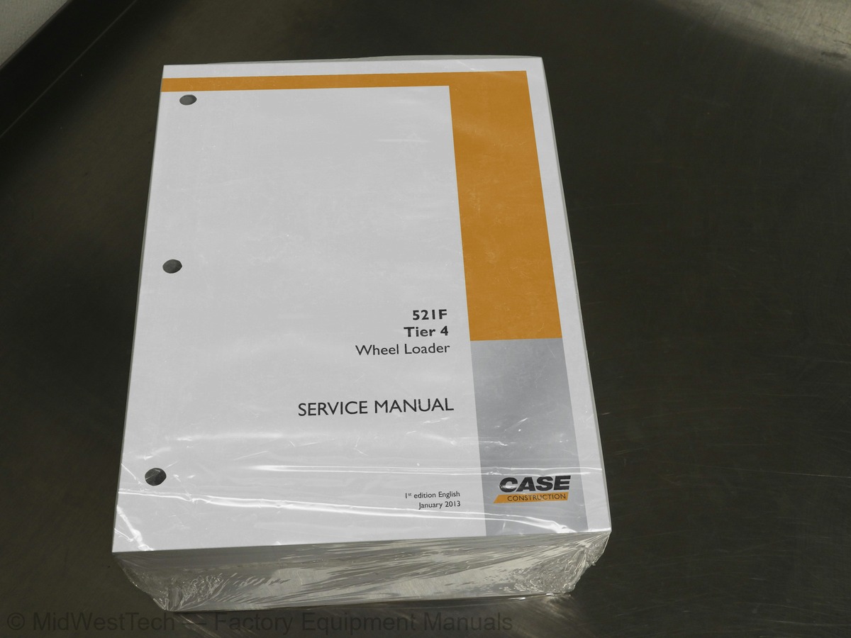
Case 521F Tier 4 Wheel Loader Service Manual
1,961 pages · Publication 47499072
Added to your cart. View cart
- Models
- 521F Tier 4
- Manual type
- Service Manual
- Pages
- 1,961
- Publication
- 47499072
- Condition
- Brand new
What's inside
From the manual's own table of contents: 142 topics. See sample pages (PDF, 615 KB)
- Foreword - Ecology and the environment
- Safety rules – California Proposition 65 Warning
- Personal safety
- Safety rules
- Torque
- Basic instructions - Important notice regarding equipment servicing
- Hydraulic contamination
- Capacities
- Product identification
- Product identification – Machine Orientation (front, right, rear, left)
- Overview
- Remove Dosing Injector – Remove
- Install Dosing Injector – Install
- Remove
- Install
- General specification Pressures
- Dynamic description
- Disassemble
- Assemble
- Testing
- Remove – Center Bearing
- Install – Center Bearing
- Remove – Center Drive Shaft
- Install – Center Drive Shaft
Show all 142 topics
- Backlash
- Assemble – DZ-1200
- Remove – Pinion
- Install – Pinion
- Remove – Brake Tube
- Install – Brake Tube
- Backlash Setting Backlash and Bearing Preload
- Check – Contact Pattern
- Install – Assembly
- Disassemble – DHL-1200
- Assemble – DHL-1200
- Cleaning
- Remove Hub Seal
- Install Hub Seal
- Limited slip - Remove – DZ-1200
- Limited slip - Disassemble – DZ-1200
- Limited slip - Assemble – DZ-1200
- Disassemble – D-1200 Differential
- Assemble – D-1200 Differential
- Remove – Pivot Pin Bushing
- Install – Pivot Pin Bushing
- Adjust – Drive Pinion Bearing Rolling Torque Adjustment
- Remove – Hub Seal
- Install – Hub Seal
- Dynamic description – Park Brake Test
- Inspect
- General specification
- Leakage test
- Bleed – Bleeding the Brake System
- Dynamic description – Hydraulic Oil Supply
- Hydraulic schematic frame 01 – 521F Tier 2\4
- Decontaminating
- Loader arm lifting electro-magnetic detent - Testing
- Remove – Overhaul
- Inspect – Overhaul
- Install – Overhaul
- Dynamic description - Troubleshooting
- Testing A/C System Test
- High pressure - Testing
- Low pressure - Testing
- Testing - Thermostat
- Electrical schematic frame 01 - Index \ Wire information
- Electrical schematic frame 02 - Schematic connector list
- Electrical schematic frame 03 - Schematic connector list
- Electrical schematic frame 04 - Cold start , Power distribution, Ignition switch
- Electrical schematic frame 05 - Engine control
- Electrical schematic frame 06 - Lighting 1, Backup Alarm
- Electrical schematic frame 07 - Lighting 2
- Electrical schematic frame 08 - Transmission Controls
- Electrical schematic frame 09 - Instrument Cluster
- Electrical schematic frame 10 - Machine controls
- Electrical schematic frame 11 - Secondary steering, Hood lift, Wiper/Washer system
- Electrical schematic frame 12 - HVAC, Air seat, Radio power/converter
- Electrical schematic frame 13 -Joystick steering
- Electrical schematic frame 14 - Standard HVAC
- Component diagram 01 - Engine control
- Component diagram 02 - Engine control
- Component diagram 03 - Engine control / emissions
- Component diagram 04 - Engine / machine controls
- Component diagram 05 - Machine controls
- Component diagram 06 - Transmission controls
- Component diagram 07 - Transmission controls
- Component diagram 08 - Transmission controls
- Component diagram 09 - Instrument cluster
- Component diagram 10 - Instrument cluster
- Component diagram 11 - Backup alarm
- Testing Ignition switch
- Testing - Starting relay
- Neutral start relay - Testing
- Visual inspection
- Charging
- Filling
- Battery main switch - Testing - Master Disconnect Switch
- Front - Testing
- Combination lamp - Testing - Left hand (LH) front combo light
- Combination lamp - Testing - Right hand (RH) front combo light
- Testing - Hazard switch
- Testing - Hi \ Low beam switch
- Testing Driving Lights Switch
- Rear - Testing
- Testing - Hazard switch light
- Testing - Turn signal switch
- Testing - Brake light pressure switch
- Testing Front Wiper
- Testing Rear Wiper
- Testing Front Washer
- Testing Wiper Cutout Relay
- Remove – Supply Tank Filler Neck Screen
- Install – Supply Tank Filler Neck Screen
- Remove – Supply Line Screen
- Install – Supply Line Screen
- Remove – DNOx Supply Module Filter
- Install – DNOx Supply Module Filter
- Remove – Upstream Exhaust Temperature Sensor
- Install – Upstream Exhaust Temperature Sensor
- Remove – Downstream Exhaust Temperature Sensor
- Install Downstream Exhaust Temperature Sensor
- 0000-Retrieving fault codes, Wheel Loaders
- 1310-Hydraulic Filter Blocked
- 1311-Engine Air Filter Blocked
- 1312-Hydraulic Oil Temperature Above Normal
- 1313-Hydraulic Oil Temperature Too High
- 1314-Transmission Oil Temperature Above Normal
- 1315-Transmission Oil Temperature Too High
- 1316-Brake Pressure Too Low
- 1317-Steering Pressure Too Low
- 1318-Engine Coolant Temperature Above Normal
- 1319-Engine Coolant Temperature High - Critical
- 1320-Engine Oil Pressure Too Low
- 1321-Engine Oil Pressure Below Normal
- 1322-Engine Oil Pressure Above Normal
- 1323-Battery Voltage Too Low
- 1324-Battery Voltage High
- 1325-Engine Oil Temperature Too High
- 1331-Electrical charging system voltage too low, critical
- 1332-Water Detected In Fuel
- 1333-Engine Overspeed
- 1334-Intake Manifold Temperature High - Critical
Inside this manual
Real pages from this service manual (1,961 pages). Open the sample pages (PDF, 614 KB)

- Troubleshooting, page 1,341: 19579-CAN Receive Frame E2SCR Timeout
- Diagram, page 1,641: 3220-Bank 2 No Signal
- Specifications, page 1,761: 4133-Short circuit to battery voltage or open circuit at transmission
- Color page, page 979: Part number 47499076
- Color page, page 195: Engine - Selective Catalytic Reduction (SCR) exhaust treatment
- Foldout diagram (color), page 855: Electrical systems - Harnesses and connectors
This is a service manual
Here's how it compares to the other manual types.
Service manual
Factory repair procedures and technical information such as specifications, troubleshooting, and wiring and hydraulic diagrams, for the models and systems the manual covers. See What's inside for its topics.
Operator's manual
Safe operation, controls, maintenance schedules, lubrication points, inspections, and basic checks. Repair procedures are in the service manual.
Parts manual
Illustrated diagrams with factory part numbers for identifying components and ordering parts. Repair procedures are in the service manual.
Engine service manuals are sometimes sold separately, since certain machine models were offered with more than one engine option.
What it's used for
Factory manual for in-house farm and construction shop use. Straightforward, complete, and easy to follow. It contains the OEM information dealership service departments and parts counters use to diagnose problems, identify components, and perform maintenance or repairs correctly.
Service shops and owner/operators who repair their own equipment
Identifying correct parts and seeing how assemblies come apart and go back together
Keeping equipment running with less downtime
Factory manual, 1,961 pages
Quantity one is the manual described above.
Fast free USA shipping
Ships in 1 business day.
60-day returns
Free if the mistake is ours. A manual ordered in error must come back unopened in its shrink-wrap; you pay return shipping and a 20% restocking fee applies. Return policy
Binder not included
Manuals over about 300 pages may need a standard 3-ring binder, which you can buy locally to keep the pages organized for shop use.
Other editions and similar models
Questions about model, serial number, engine coverage or contents? Contact us before purchasing and we'll help confirm it's the right manual. Please verify the manual type, machine model, serial number range and engine coverage before purchasing: manuals ordered in error carry a 20% restocking fee (return policy).