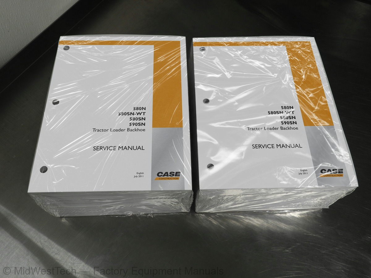
Case 580N, 580SN-WT, 580SN, 590SN Tractor Loader Backhoe Service Manual
2,913 pages · Publication 84516378
Added to your cart. View cart
What's inside
From the manual's own table of contents: 386 topics. See sample pages (PDF, 969 KB)
- PRIMARY HYDRAULIC POWER SYSTEM
- SECONDARY HYDRAULIC POWER SYSTEM
- ELECTRICAL POWER SYSTEM
- FAULT CODES
- ENGINE AND PTO IN
- ENGINE
- FUEL AND INJECTION SYSTEM
- EXHAUST SYSTEM
- ENGINE COOLANT SYSTEM
- STARTING SYSTEM
- TRANSMISSION, DRIVE AND PTO OUT
- TRANSMISSION Power Shuttle
- TRANSMISSION Powershift
- AXLES, BRAKES AND STEERING
- FRONT AXLE
- REAR AXLE
- STEERING Hydraulic
- SERVICE BRAKE Hydraulic
- PARKING BRAKE Mechanical
- WHEELS AND TRACKS Wheels
- FRAME AND CAB
- FRAME Primary frame
- SHIELD
- USER CONTROLS AND SEAT
Show all 386 topics
- USER CONTROLS AND SEAT Operator seat
- USER PLATFORM
- Safety rules
- Battery - Basic instructions
- ELECTRONIC SYSTEM - Basic instructions
- Heater - Basic instructions
- Basic instructions
- Torque
- Abbreviation Measurements
- Capacities
- Consumables
- Special tools
- General specification
- General specification - Ride control
- Special tools - Ride control
- Exploded view
- Exploded view - Hydraulic gear pump, 580N only
- Exploded view Hydraulic Pump 580SN, 580SN WT and 590SN
- Exploded view - Hydraulic gear pump seal, 580N only
- Hydraulic schema Regulated manifold hydraulic schematic, Pilot Controls Only
- Exploded view - Regulated manifold, Pilot Controls only
- Exploded view 580N Pilot Machines only
- Exploded view 580SN, 580SN WT and 590SN machines with pilot controls
- Component diagram - Pilot control color codes
- Drawing Remote Clam Valve for 580SN, 580SN WT and 590SN with Pilot Controlled Backhoe
- Drawing 580N Mechanically Controlled Machines
- Drawing 580SN, 580SN WT and 590SN Mechanically Controlled Machines
- Pilot Controlled Machines
- Drawing Relief Valve, Loader Dump, Backhoe Swing on mechanically controlled Backhoes
- with mechanical backhoe controls
- Drawing Single Stage Relief Valve, 580 Main Relief with mechanical backhoe controls
- Drawing Relief Valve, Main System Dual Stage for 580N with Pilot Controlled Backhoe
- Drawing Load Sense Relief Valve, 580N with Pilot Controlled Backhoe
- Sectional view Hydraulic Pump, 580N only
- Exploded view - Extendahoe
- Exploded view - Extendahoe hose routing
- Exploded view - Coupler hose routing
- Exploded view - Coupler cylinder
- Exploded view - Quick coupler cylinder
- Exploded view - Swing dampening valve
- Sectional view Backhoe and Loader Quick Coupler Single Valve
- Sectional view Backhoe and Loader Quick Coupler Dual Valve
- Remove - Hydraulic backhoe quick coupler
- Install - Hydraulic backhoe quick coupler
- Disassemble - Quick coupler cylinder
- Inspect - Quick coupler cylinder
- Assemble - Quick coupler cylinder
- Disassemble - Swing dampening valve
- Inspect - Swing dampening valve
- Assemble - Swing dampening valve
- Check - Swing Cushion Valve (Swing Drift Troubleshooting)
- General specification - Electrical wire circuits - 580N only
- Component diagram 01 Side Console Harness Connectors
- Component diagram 02 Front Console Harness. SPS/PWR Trans, Mech W/ Opt
- Component diagram 03 Chassis Harness
- Component diagram 04 Cab Rear Lights Harness
- Component diagram 05 Front Lights Canopy Harness
- Component diagram 06 Hydraulic Filter Restriction Jumper Harness
- Component diagram 07 Cab B-Post Harness
- Component diagram 08 C-Post Harness
- Component diagram 09 Combo Aux, Mech Control, Hammer or BiDir Valve Harness
- Component diagram 10 Combo Aux, Pilot Control, Hammer or Bi-Dir Valve Harness
- Component diagram 11 Combo Aux, Mech Control Hammer Valve Only Harness
- Component diagram 12 Combo Aux, Pilot Control, Hammer Valve Only
- Component diagram 13 A-Post Harness
- Component diagram 14 A-Post, Canopy, Harness
- Component diagram 15 Rear Lights, Canopy, Harness
- Component diagram 16 Rear Lights, Canopy, Harness (6 lights)
- Component diagram 17 Pilot Controls Harness
- Component diagram 18 Front Lights, Cab Harness
- Component diagram 19 Front Lights Canopy Harness
- Component diagram 20 Power shift jumper harness
- Component diagram 21 Side console, SPS/PWR Trans, HPCR, W/opt harness
- Electrical schematic frame 01 Power Distribution/ Charging System
- Electrical schematic frame 02 Starting System
- Electrical schematic frame 03 Grounding
- Electrical schematic frame 04 Engine Control
- 0000-Retrieving fault codes, Backhoes
- 1001-Engine Air Filter Blocked
- 1002-Engine coolant temperature too high, critical
- 1003-Air conditioning pressure too high
- 1004-Hydraulic filter blocked
- 1009-Transmission oil temperature too high
- 1010-Foot throttle signal out of range, IVS not changing state in 300 ms
- 1011-Foot throttle signal out of range, throttle above 95% of input for 5 seconds
- 1012-Foot throttle signal out of range, throttle below 5% of input for 5 seconds
- 1013-Foot throttle signal out of range, signal unusable
- 1014-Battery charge voltage too high
- 1015-Battery charge voltage too low
- 1018-Boost air temperature too high
- 1019-Engine coolant temperature too high
- 1020-Transmission oil temperature above normal
- 1021-Fuel temperature above normal
- 1022-Water in fuel
- 1023-Foot throttle supply voltage too high, over 5.2 volts for 5 seconds
- 1024-Foot throttle supply voltage too low, under 4.8 volts for 5 seconds
- 1025-Foot throttle sensor voltage over 5.3 volts for 5 seconds
- 1026-Foot throttle sensor voltage under 200 mV for 5 seconds
- 1032-Hand throttle supply voltage too low, under 4.8 volts for 5 seconds
- 1033-Hand throttle sensor voltage over 5.3 volts for 5 seconds
- 1034-Hand throttle sensor voltage under 200 mV for 5 seconds
- 1035-Hand throttle sensor signal above 95% of input for 5 seconds
- 1036-Hand throttle sensor signal below 5% of input for 5 seconds
- 1037-Hand throttle sensor out of range
- 1039-Hand throttle sensor voltage under 200 mV for 5 seconds
- 1040-Engine RPM over 2750 for 5 seconds
- 1041-Engine RPM over 3000 for 5 seconds
- Speeds stall test normal (all models)
- Speeds stall test check sheet (580N only)
- Speeds stall test check sheet (580SN only)
- Speeds stall test check sheet (590SN only)
- Speeds stall test check sheet (580SN WT only)
- Service instruction - Engine repair service manual
- Remove - 580N only
- Install - 580N only
- Prepare for stall tests
- Remove
- Timing adjust
- Exploded view - Throttle linkage
- Adjust - Throttle linkage adjustment
- Adjust - Throttle lever adjustment
- Timing check
- Install
- Exploded view - 580N only
- Exploded view - 580SN, 580SN-WT, 590SN only
- Remove - 580 only
- Disassemble 580N only
- Assemble 580N only
- Disassemble - 580SN, 580SN-WT, 590SN only
- Remove - Starter
- Install - Starter
- Test
- Inspect
- Test - Field coil test
- Exploded view - Four wheel drive transmission
- Exploded view - Two wheel drive transmission
- Hydraulic schema - Two Wheel Drive Schematic
- Hydraulic schema - Four Wheel Drive Schematic
- Exploded view - Four wheel drive valve (if equipped)
- Exploded view - Transmission control valve
- Exploded view - Input shaft
- Exploded view - Shift rod and forks
- Exploded view - Secondary shaft
- Exploded view - Four wheel drive shaft
- Check Checking Supply Pump Pressure (4WD Only)
- Test - Checking Converter In Pressure
- Test - Checking Regulated Clutch Pressure
- Test Checking Supply Pump Flow and Relief Pressure
- Test - Checking Converter Out Pressure
- Test Checking Lubrication Pressure
- Test - Checking Differential Lock Valve
- Pressure test – 2 Wheel Drive, Test One - Engine at Idle 900 to 1100 rpm
- General specification - H-type
- General specification - S-Type
- Torque - S-type (SPS Power Synchro)
- General specification - H-type - 4WD only
- Special tools - H-type - 4WD only
- Torque - H-type - 4WD only
- General specification Trax Controller Pin Out Guide, S-Type Transmission
- Exploded view - Powershift H-type
- Exploded view - H-type - 1st, 3rd, 4th gear shaft
- Exploded view - H-type - transmission assembly - 4 wheel drive shaft
- Exploded view - S-Type (SPS Power Synchro) - Filters
- Exploded view - S-type (SPS Power Synchro) - Oil pump
- Exploded view - S-Type (SPS Power Synchro) - Switches and sensors
- Exploded view - S-Type (SPS Power Synchro) - Hydraulic control valve
- Exploded view - S-Type (SPS Power Synchro) - Front housing
- Exploded view - S-Type (SPS Power Synchro) - Rear cover
- Exploded view - S-Type (SPS Power Synchro) - Gear pistons
- Exploded view - S-type (SPS power synchro) - Shaft A - D
- Exploded view - S-Type (SPS Power Synchro) - Shafts B - C
- Exploded view -S-type (SPS power synchro) - transmission assembly - 4 wheel drive shaft
- Exploded view - S-Type (SPS Power Synchro) - Shift rails - forks
- Overview S-Type Transmission
- Hydraulic schema H-Type
- Hydraulic schema S-Type
- Drawing H-Type
- General specification - Carraro Front axle two wheel drive
- Special tools - Carraro Front axle two wheel drive
- General specification - CNH Front Axle - Two Wheel Drive
- Special tools - CNH Front axle Two Wheel Drive
- General specification - CNH Front Axle Four Wheel Drive - 580N and 580SN
- General specification - CNH Front Axle Four Wheel Drive - 580SN-WT and 590SN
- Special tools - CNH Front Axle Four Wheel Drive - 580N, 580SN, 580SN-WT, 590SN
- General specification - Carraro Front axle-four wheel drive - 580N and 580SN only
- Special tools - Carraro Front axle-four wheel drive - 580N and 580SN only
- General specification - Carraro Front axle-four wheel drive - 580SN-WT and 590SN only
- Special tools - Carraro Front axle-four wheel drive - 580SN-WT and 590SN only
- Exploded view - CNH Four wheel drive axle
- Drawing - Front axle-four wheel drive- measuring toe-in
- Exploded view - Carraro Front axle-four wheel drive - 580N and 580SN only
- Exploded view - Carraro Front axle-four wheel drive - 580SN-WT and 590SN only
- Exploded view - CNH- Front Axle - Differential
- Exploded view - Carraro Front axle- swivel housing
- Exploded view - CNH Front axle - swivel housing
- Exploded view - Carraro Front axle-four wheel drive - 580SN-WT
- Exploded view - Carraro Front axle-four wheel drive - 590SN
- Exploded view - CNH Front Axle - Planetary
- General specification - 580N and 580SN only
- Special tools - 580N and 580SN only
- General specification - 580SN-WT and 590SN only
- Special tools - 580SN-WT and 590SN only
- Exploded view - Differential lock
- Exploded view - Differential - 580N and 580SN only
- Exploded view - Ring and pinion
- Exploded view - Differential - 580SN-WT and 590SN only
- Drawing - Axle housing
- Exploded view - Wheel hub and final reduction unit
- Remove - Carrier removal 580N and 580SN only
- Disassemble - 580N and 580SN only
- Remove - Differential lock fork removal - 580N and 580SN only
- Install - Differential lock housing and piston - 580N and 580SN only
- Install - Differential lock fork installation - 580N and 580SN only
- Assemble - 580N and 580SN only
- Adjust - Pinion gear backlash adjustment - 580N and 580SN only
- Adjust - Differential bearing preload adjustment - 580N and 580SN only
- Install - Pinion shaft seal installation - 580N and 580SN only
- Install - Carrier installation - 580N and 580SN only
- Check - Checking the differential lock - 580N and 580SN only
- General specification - Steering relief valve
- General specification - Rotor and stator clearance
- Special tools - Pressure fitting kit
- Special tools - Rotor and stator clearance
- Drawing - Steering control valve
- Drawing - Optional comfort steering control valve
- Exploded view - 580SN-WT only
- Exploded view - Comfort steering valve
- Exploded view - Steering control valve - Standard Steering
- Sectional view Standard Steering Control Valve
- Sectional view Optional Comfort Steering Control Valve
- Exploded view - Two wheel drive steering cylinder
- Exploded view - Front console
- Exploded view - Cab models
- Exploded view - Canopy models
- Exploded view - Brake pedal
- Exploded view - Brakes
- Adjust - Brake pedal height adjustment
- Remove - Removing air from the brake system
- Disassemble
- Assemble
- Check
- Torque - Front wheel mounting nut torque procedure
- Tire pressure - 580N and 580SN only
- Tire pressure - 580SN-WT only
- Tire pressure - 590SN only
- Torque - Rear wheel mounting nut torque procedure
- Exploded view - Backhoe controls with foot swing
- Exploded view - Backhoe controls with hand swing
- Adjust - Adjustment of the backhoe control levers
- Disassemble - Air suspension seat
- Inspect - Air suspension seat
- Assemble - Air suspension seat
- Visual inspection
- Check - Instrument cluster
- Replace - Pivot safety switch
- Disassemble - Pedestal seat
- Inspect - Pedestal seat
- Assemble - Pedestal seat
- Disassemble - Mechanical suspension seat
- Inspect - Mechanical suspension seat
- Assemble - Mechanical suspension seat
- Exploded view Rear window
- Exploded view - Door
- Exploded view - Side window
- Remove Cab
- Install Cab
- Remove Rops cab
- Remove - Rear window - top
- Install - Rear window - top
- Remove - Rear window - middle
- Install - Rear window - middle
- Remove - Rear window - bottom
- Install - Rear window - bottom
- Overview - Safety procedures
- Overview - Operation
- Exploded view - Clutch assembly
- Charging - Air conditioner system evacuation and recharging
- Pressure test and temperature testing
- Adjust - Belt check and adjustment
- Check - Oil level check
- Disassemble - Clutch disassembly
- Assemble - Clutch assembly
- Check - Condenser, receiver-drier, and tubes
- Remove Evaporator Core
- Test Expansion valve testing
- Remove Loader Lift Cylinder
- Install Loader Lift Cylinder
- Remove Loader Cylinder and Link
- Install - Loader Cylinder and Link
- Torque - Boom cylinder
- Exploded view - Boom cylinder (all models)
- Exploded view - Boom
- Pressure test
- Replace
- Remove - Boom cylinder
- Disassemble - Boom cylinder
- Overhaul - Boom cylinder
- Assemble - Boom cylinder
- Install - Boom cylinder
- Remove - Boom
- Install - Boom
- Torque - Swing cylinder
- Exploded view - Swing tower cylinder
- Sectional view - Swing cylinder
- Sectional view
- Overview - 580N with mechanical linkage controls
- Overview - 580SN, 580SN WT, and 590SN with mechanical linkage controls
- Overview - All models with pilot controls
- Remove - Swing cylinder (all models)
- Disassemble - Swing cylinders (all models)
- Overhaul - Swing cylinders (all models)
- Assemble - Swing cylinders
- Install - Swing cylinders (all models)
- Torque - Dipper cylinder
- Exploded view - Dipper cylinder
- Remove - Dipper cylinder
- Disassemble - Dipper cylinder
- Overhaul - Dipper cylinder
- Assemble - Dipper cylinder
- Install - Dipper cylinder
- Remove - Backhoe Boom
- Install Backhoe Boom
- Torque - Extendable dipper cylinder
- Exploded view - Extendable dipper installation - 580N
- Exploded view - Extendable dipper installation - 580SN, 580SN-WT
- Exploded view - Extendable dipper installation - 590SN
- Exploded view - Extendable dipper cylinder
- Remove Dipper Arm
- Replace - Wear plates - extendable dipper - 580N only
- Replace - Wear plates - extendable dipper - 580SN, 580SN-WT, 590SN
- Torque - Arm tool attachment cylinder
- Remove - Backhoe Dipper Cylinder
- Install Backhoe Dipper Cylinder
- General specification - Weld specifications for standard bucket
- Exploded view - Adjustment for return to dig
- Exploded view - Antirollback
- Exploded view - Loader lift bucket control - 580SN-WT only
- Exploded view - Loader lift bucket control - N and SN machines
- Exploded view - Loader frame
- Exploded view - Bucket frame
- Exploded view - Lift cylinder hydraulic installation
- Exploded view - Bucket cylinder hydraulic installation
- Exploded view - Clam cylinder circuit
- Exploded view - Clam cylinder hydraulic installation
- Exploded view - Antirollback linkage
- Drawing - Boom latch mechanical linkage machines
- Drawing - Boom latch pilot controlled machines
- Exploded view - Backhoe auxiliary control
- Drawing - Bucket teeth locations
- Sectional view Clam Control Valve - Clam Lock Valve
- Adjust - Adjustment for return to dig
- Adjust - Adjustment of antirollback
- Replace - Replacement of weld on cutting edge for standard buckets
- Replace - Replacement of bolt - on cutting edge for standard bucket
- Replace - Replacement of bolt - on cutting edge for clam bucket
- Replace - Replacement of tooth shank
- Torque - Special torques
- Exploded view - Mechanical linkage backhoe machines only
- Exploded view - Typical cylinder
- Check - Mechanical linkage backhoe machines only
- Remove - Mechanical linkage backhoe machines only
- Install - Mechanical linkage backhoe machines only
Inside this manual
Real pages from this service manual (2,913 pages). Open the sample pages (PDF, 969 KB)
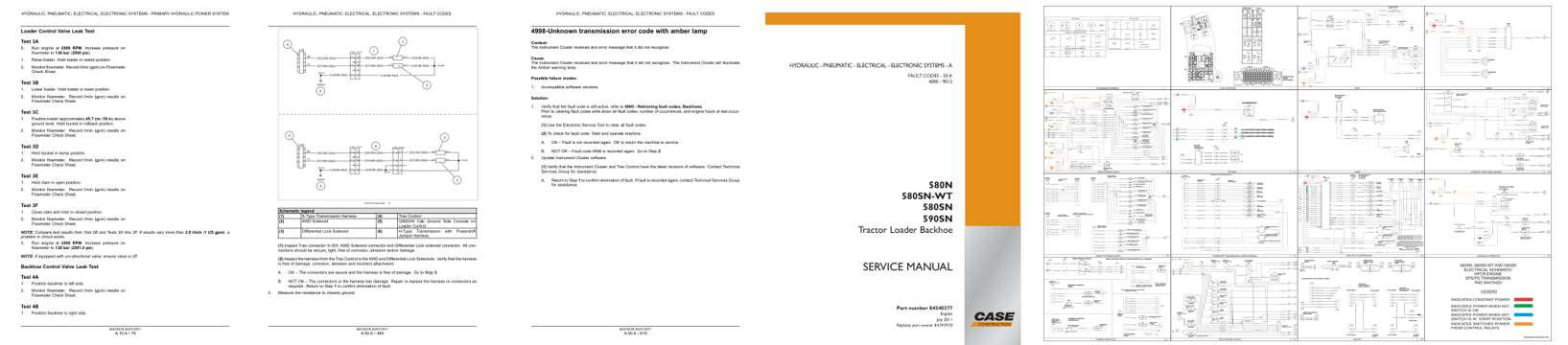
- Specifications, page 164: Loader Control Valve Leak Test
- Diagram, page 1,019: HYDRAULIC, PNEUMATIC, ELECTRICAL, ELECTRONIC SYSTEMS - FAULT CODES
- Troubleshooting, page 1,154: HYDRAULIC, PNEUMATIC, ELECTRICAL, ELECTRONIC SYSTEMS - FAULT CODES
- Color page, page 943: Part number 84540377
- Foldout diagram (color): ACTUATORS
Other manuals for this machine
Save 10% on 2 manuals, 15% on 3 or more. Other manuals are listed below. Editions cover different serial number ranges: check the serial coverage and tick only the ones that match your machine.
Added to your cart. View cart
This is a service manual
Here's how it compares to the other manual types.
Service manual
Factory repair procedures and technical information such as specifications, troubleshooting, and wiring and hydraulic diagrams, for the models and systems the manual covers. See What's inside for its topics.
Operator's manual
Safe operation, controls, maintenance schedules, lubrication points, inspections, and basic checks. Repair procedures are in the service manual.
Parts manual
Illustrated diagrams with factory part numbers for identifying components and ordering parts. Repair procedures are in the service manual.
Engine service manuals are sometimes sold separately, since certain machine models were offered with more than one engine option.
What it's used for
Factory manual for in-house farm and construction shop use. Straightforward, complete, and easy to follow. It contains the OEM information dealership service departments and parts counters use to diagnose problems, identify components, and perform maintenance or repairs correctly.
Service shops and owner/operators who repair their own equipment
Identifying correct parts and seeing how assemblies come apart and go back together
Keeping equipment running with less downtime
Factory manual, 2,913 pages
Quantity one is the manual described above.
Fast free USA shipping
Ships in 1 business day.
60-day returns
Free if the mistake is ours. A manual ordered in error must come back unopened in its shrink-wrap; you pay return shipping and a 20% restocking fee applies. Return policy
Binder not included
Manuals over about 300 pages may need a standard 3-ring binder, which you can buy locally to keep the pages organized for shop use.
Other editions and similar models
Questions about model, serial number, engine coverage or contents? Contact us before purchasing and we'll help confirm it's the right manual. Please verify the manual type, machine model, serial number range and engine coverage before purchasing: manuals ordered in error carry a 20% restocking fee (return policy).