MidWestTechService, Parts and Operator's Manuals, in stock and ready to ship!
Fast free USA shippingShips in 1 business daySave 10% on 2 manuals, 15% on 3+

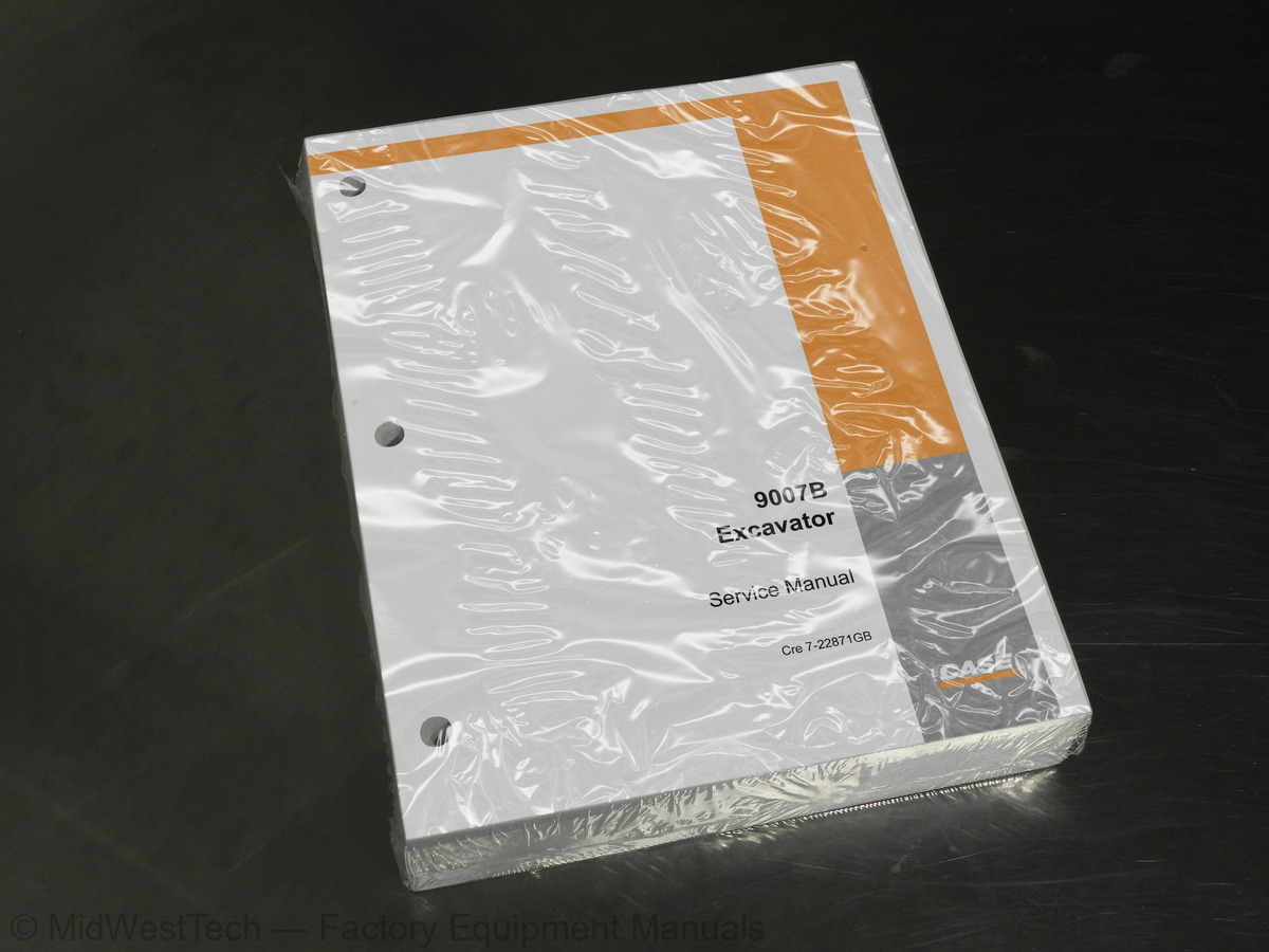
Case 9007B Excavator Service Manual

532 pages · Publication 7-22241

$69.77
Fast free USA shippingShips in 1 business daySave 10% on 2 manuals, 15% on 3 or morePay by credit or debit card or with PayPal. No PayPal account needed.
Models
9007B
Manual type
Service Manual
Pages
532
Publication
7-22241
Condition
Brand new
Case 9007B Excavator Service Manual, publication 7-22241

What's inside

From the manual's own table of contents: 169 sections, 176 entries. See sample pages (PDF, 1056 KB)

SPECIFICATIONS
SPECIAL TORQUES
ENGINE
Removal and installation
SCHEMATIC SYMBOLS
MAXI-FUSES
FUSES
RELAYS
OPERATOR’S COMPARTMENT
MONITOR DISPLAY
LEFT-HAND SWITCH PANEL
RIGHT-HAND SWITCH PANEL
ELECTRICAL SCHEMATIC (PLATE A)
ELECTRICAL SCHEMATIC (PLATE B)
ELECTRICAL SCHEMATIC (PLATE C)
ELECTRICAL SCHEMATIC (PLATE D)
ELECTRICAL SCHEMATIC (PLATE E)
ELECTRICAL SCHEMATIC (PLATE F)
THROTTLE MOTOR
THROTTLE MOTOR DRIVER
ENGINE SPEED CONTROL
HYDRAULIC CONTROL
OTHERS
THROTTLE CONTROL ASSEMBLY ADJUSTMENT METHOD
Show all 169 sections
THROTTLE MOTOR LEVER ANGLE ADJUSTMENT
INJECTION PUMP LEVER ANGLE ADJUSTMENT
COMPONENT ELECTRICAL TESTING
System voltage
Amp/hour rating
SAFETY RULES
MAINTENANCE
Electrolyte Level
Inspecting and Cleaning a Battery
BATTERY TEST
Visual Checks
Specific Gravity Check
Capacity (Load) Test
CHARGING THE BATTERY
CHARGING GUIDE FOR BATTERIES
BOOSTER BATTERY CONNECTIONS
SPECIAL TOOLS
STEEL TRACKS
Removal
Installation
RUBBER TRACKS (Optional)
Inspection
TRACK TENSION ADJUSTMENT
CHECKING PIN AND BUSHING WEAR
TURNING PINS AND BUSHINGS
SPROCKET
Reconditioning
LOWER ROLLER
Disassembly
Assembly
UPPER ROLLER
IDLER WHEEL
TOOLS REQUIRED
TRAVEL MOTOR-REDUCTION GEAR ASSEMBLY
Exploded view
Cross-sectional view
Precautions to be taken before disassembly
Precautions to be taken before assembly
Assembly instructions
Adjusting the bearing pre-load
Bearing axial clearance adjustment
GENERAL INFORMATION
TYPES OF CONTAMINATION
CLEANING THE HYDRAULIC SYSTEM
Test instrument
LOCATION OF COMPONENTS
IDENTIFICATION OF HYDRAULIC COMPONENTS
Pumps
Control valve
Control block
Dozer blade valve
FUNCTIONS AND OPERATING PRINCIPLES
Table of functions
TRAVEL CIRCUIT
Travelling in first speed
Travelling in second speed
Travelling in a straight line
UPPERSTRUCTURE SWING CIRCUIT
Operation without swing
Swing function
Swing function during braking phase
Swing and arm function
Swing lock function
REDUCTION GEAR LUBRICATION
ATTACHMENT CIRCUITS
Raising the boom
Lowering the boom
Extending the arm
Retracting the arm
Opening the bucket
Closing the bucket
DOZER BLADE CIRCUIT
Raising the blade
Lowering the blade
MISCELLANEOUS CIRCUITS
OPTION CIRCUIT
Hydraulic hammer (only)
Hydraulic hammer or concrete crusher
GENERAL INSPECTION PROCEDURES
PRESSURE SETTING DIAGRAM
Location of main hydraulic components
Location of adjustment points
Location of inspection points
OPERATIONS TO BE CARRIED OUT BEFORE ANY INSPECTION OR ADJUSTMENT
BRINGING THE HYDRAULIC OIL UP TO THE RIGHT OPERATING TEMPERATURE
CHECKING THE ATTACHMENT CONTROL VALVE MAIN RELIEF VALVE
Inspection procedure
Adjustment procedure
WORKSHOP TOOLS
TOOLS TO BE MADE
HYDRAULIC PUMP
Port identification
Adjustments
Cross-sectional view (main pump)
Cross-sectional view (regulator)
Cross-sectional view (double body gear pump)
Safety precautions before assembly
Removing the gear pump assembly
Removing the cover
Disassembling the regulator block
Disassembling the gear pump
Servo-pump
Inspecting and checking
Assembly procedure
Gear pump assembly
Assembling the servo-pump
Safety measures
SPECIAL TORQUE SETTINGS
TOOLS TO BE MANUFACTURED
BOOM CYLINDER
Description
DIPPER CYLINDER
BUCKET CYLINDER
DOZER BLADE CYLINDER
Inspection and maintenance
General working instructions
Inspection after assembly
Evaluation of size of leaks as per appearance of rod
Troubleshooting
HAND CONTROL VALVES
Adjustment
FOOT CONTROL VALVES
MAINTENANCE PROCEDURES
Tools and tightening torque
Maintenance standards
OPTION - DOZER BLADE - TRAVEL PEDAL
SHUTTLE VALVE
TRAVEL SHUTTLE VALVE
ELECTRO-CONTROL VALVE BLOCK
System diagram
Maintenance and replacement of components
Type7 topics
  • Plug (12) of main relief valve
  • Plug (31) of non-return valve
  • Plug (31) of system shut-off valve 1
  • Attaching screw (33) of body (17)
  • Plug (31) of pressure reducer
  • Seat (2) of shuttle ball
  • Attaching screw (32) of solenoid
CUSHION VALVE
Servicing
Connector (4)
HYDRAULIC SWIVEL
Weight
Lock Bar Installation Cap Screws
TURNTABLE WEAR INSPECTION
UPPERSTRUCTURE
TURNTABLE LUBRICATION
COUNTERWEIGHT
BUCKET
BOOM
BLADE

Inside this manual

Real pages from this service manual (532 pages). Open the sample pages (PDF, 1055 KB)
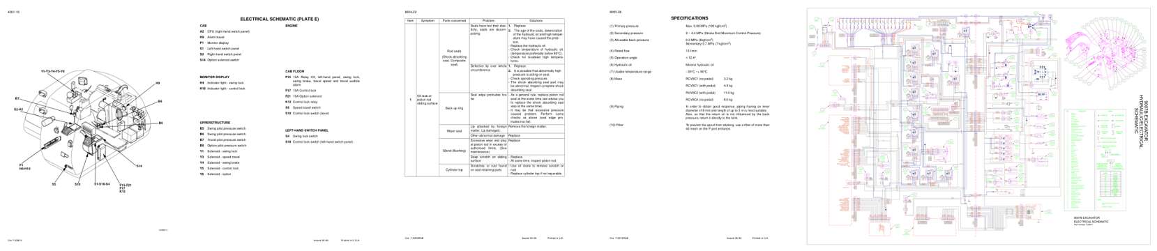
Sample pages from the Case 9007B Excavator Service Manual: Diagram, Troubleshooting, Specifications, Foldout diagram (color)
  • Diagram, page 64: Issued 02-99
  • Troubleshooting, page 376: Cre 7-22090GB
  • Specifications, page 408: Cre 7-22100GB
  • Foldout diagram (color), page 531: WORKING

This is a service manual

Here's how it compares to the other manual types.

This manual

Service manual

Factory repair procedures and technical information such as specifications, troubleshooting, and wiring and hydraulic diagrams, for the models and systems the manual covers. See What's inside for its topics.

Operator's manual

Safe operation, controls, maintenance schedules, lubrication points, inspections, and basic checks. Repair procedures are in the service manual.

Parts manual

Illustrated diagrams with factory part numbers for identifying components and ordering parts. Repair procedures are in the service manual.

Engine service manuals are sometimes sold separately, since certain machine models were offered with more than one engine option.

What it's used for

Factory manual for in-house farm and construction shop use. Straightforward, complete, and easy to follow. It contains the OEM information dealership service departments and parts counters use to diagnose problems, identify components, and perform maintenance or repairs correctly.

Service shops and owner/operators who repair their own equipment

Identifying correct parts and seeing how assemblies come apart and go back together

Keeping equipment running with less downtime

Factory manual, 532 pages

Quantity one is the manual described above.

Fast free USA shipping

Ships in 1 business day.

60-day returns

Free if the mistake is ours. A manual ordered in error must come back unopened in its shrink-wrap; you pay return shipping and a 20% restocking fee applies. Return policy

Binder not included

Manuals over about 300 pages may need a standard 3-ring binder, which you can buy locally to keep the pages organized for shop use.

Questions about model, serial number, engine coverage or contents? Contact us before purchasing and we'll help confirm it's the right manual. Please verify the manual type, machine model, serial number range and engine coverage before purchasing: manuals ordered in error carry a 20% restocking fee (return policy).