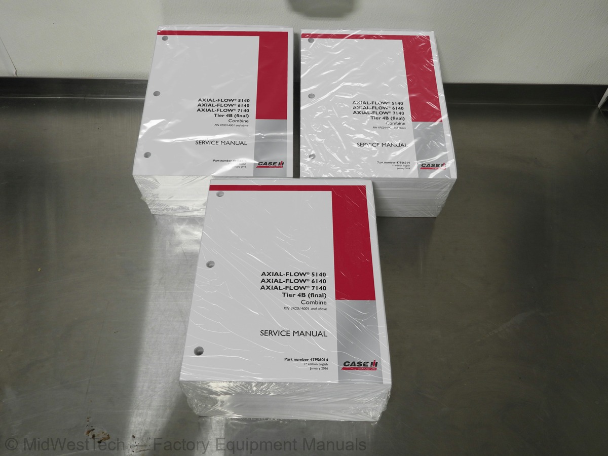
Case Axial Flow 5140, 6140, 7140 Tier 4B Combine Service Manual
5,627 pages · Publication 47956014
Added to your cart. View cart
- Models
- Axial Flow 5140, 6140, 7140 Tier 4B
- Serial coverage
- PIN YFG01400I and above
- Manual type
- Service Manual
- Pages
- 5,627
- Publication
- 47956014
- Condition
- Brand new
What's inside
From the manual's own table of contents: 535 topics. See sample pages (PDF, 620 KB)
- Foreword - Important notice regarding equipment servicing
- Safety rules - Ecology and the environment (*)
- Safety rules - Personal safety (*)
- Safety rules (*)
- Basic instructions - Shop and assembly
- Torque - Minimum tightening torques for normal assembly (*)
- Torque - Standard torque data for hydraulics (*)
- Basic instructions - Chain Wear Tables - Roller Chains (*)
- General specification
- Dimension
- Capacities
- Product overview
- Product identification
- Frame - Product identification - Machine orientation
- Engine and crankcase
- Air cleaners and lines
- Fuel filters
- Lift pump and lines
- Fuel tanks
- Intake and exhaust manifolds and muffler
- Engine lubrication system
- Aftercooler
- Engine cooling system
- Oil cooler and lines
Show all 535 topics
- Fan and drive
- Stationary air screen
- Engine air compressor
- Selective Catalytic Reduction (SCR) exhaust treatment
- Remove engine oil drain line and drain valve
- Install engine oil drain line and drain valve
- Change fluid – Maintenance Chart – Recommended operating temperature range (*)
- Remove engine serpentine belt (*)
- Install engine serpentine belt (*)
- Install 5140 Engine (*)
- Drain fluid
- Remove
- Install
- Remove - filter element
- Remove (*)
- Install (*)
- Remove mixer tube
- Install mixer tube
- Remove exhaust tube from turbo charger to Diesel Oxidation Catalyst (DOC) (*)
- Install exhaust tube from turbo charger to Diesel Oxidation Catalyst (DOC) (*)
- Change fluid
- Check
- Filling engine oil
- Replace
- Remove intercooler heat exchanger (charge air cooler radiator)
- Install intercooler heat exchanger (charge air cooler radiator)
- Remove return air tube from cooler to intake manifold (*)
- Install return air tube from cooler to intake manifold (*)
- Remove air supply tube from turbocharger to upper cooler box
- Install air supply tube from turbo charger to upper cooler box
- Remove air supply tube from turbocharger to lower cooler box
- Install air supply tube from turbocharger to lower cooler box
- Capacity
- Drain fluid (*)
- Filling (*)
- Remove - fan shroud
- Install - fan shroud
- Adjust
- Disassemble
- Assemble
- Remove fan drive belts
- Install fan drive belts
- Rotary screen - Overview of the Stationary Air Screen (SAS) (*)
- Rotary screen - Component identification (*)
- Remove belt
- Install belt
- Remove - belt tensioner assembly
- Install - belt tensioner assembly
- Remove - driven pulley
- Install - driven pulley
- Remove - vacuum nozzle
- Install - vacuum nozzle
- Remove - fixed screen outer duct
- Install - fixed screen outer duct
- Replace – Tank fill screen
- Filling
- Remove coolant hoses
- Install coolant hoses
- Replace - in line filter
- Disconnect the doser DEF/AdBlue® supply hose
- Connect the doser DEF/AdBlue® supply hose
- Replace in-line filter
- Replace tank vent filter
- Torque PTO Housing Service (*)
- Component identification (*)
- Exploded view (*)
- Visual inspection and shimming the PTO input shaft drive gear
- Check Shimming the Bevel Pinion Gear (*)
- Backlash (*)
- Gear tooth contact
- Remove Separator Shaft
- Disassemble Separator Shaft
- Assemble Separator Shaft
- and drive - Install separator drive housing assembly
- Remove PTO Input Shaft
- Disassemble PTO Input Shaft
- Assemble PTO Input Shaft
- Install PTO Input Shaft
- Mechanical transmission lubrication system
- Mechanical transmission
- Mechanical transmission internal components
- Gearbox internal components
- Differential
- Remove - suction screen
- Install - suction screen
- Torque Special
- Component identification
- Sectional view
- Static description
- Service instruction General Information (*)
- Remove top cover
- Install top cover
- Disassemble top cover
- Assemble top cover
- Remove - mechanical transmission
- Install - mechanical transmission
- Component identification Input Housing
- Remove bearings
- Install bearings
- End play on the driven shaft (shimming)
- Remove input shaft
- Disassemble input shaft
- Assemble input shaft
- Install input shaft
- End play on the input shaft (shimming)
- Component identification Change Gear Shaft
- End play verification
- Assemble differential assembly
- Torque - Bull Gear Type - HD2 11:111 Ratio
- Special tools - Bull Gear Type - 11:111 Ratio
- General specification - Bull Gear Type - HD2 11:111 Ratio
- Sectional view - Bull Gear Type - HD2 11:111 Ratio
- Exploded view
- Remove - Bull Gear Type - HD2 11:111 Ratio
- Install - Bull Gear Type - HD2 11:111 Ratio
- Disassemble - Bull Gear Type - 11:111 Ratio
- Visual inspection - Bull Gear Type - 11:111 Ratio
- Assemble - Bull Gear Type - HD2 11:111 Ratio
- Configure Axle Extension Positions
- Dynamic description
- Exploded view Steering Axle Assembly
- Alignment
- Remove steering bushing
- Install steering bushing
- Transmission and steering hydrostatic control
- Hydrostatic transmission
- Reservoir, cooler, and lines
- Pump and motor components
- Hydraulic schema - High Speed Pump Circuit
- Hydraulic schema - Low Speed Pump Circuit
- Hydraulic schema - High Speed Motor Circuit
- Hydraulic schema - Low Speed Motor Circuit
- Relief valve - Static description of Charge Pressure Relief Valve (*)
- Remove valve
- Install valve
- Overview
- Dynamic description of Swashplate (*)
- Dynamic description of Neutral Operation (*)
- Dynamic description of Hydrostatic Ground Drive (*)
- Static description of Neutral Operation (*)
- Static description - for the Eaton low speed hydrostatic drive
- Adjust propulsion control (*)
- Pressure test Drive pressure
- Dynamic description of Variable Displacement Pump and Motor (*)
- Identification (*)
- Static description Charge Pump (*)
- Exploded view Power Guide Axle (*)
- Remove Hydrostatic Drive Pump
- Disassemble Hydro Pump Drive Assembly
- Assemble Hydro Pump Drive Assembly
- Install Hydrostatic Drive Pump
- Bleed Hydrostatic System
- Inspect Hydrostatic Drive Pump (*)
- Disassemble - Charge pump (*)
- Assemble - Charge pump (*)
- Remove - Multi-Function Handle control cable
- Install - Multi-Function Handle control cable
- Pressure test servo
- Pressure test hydrostatic pump charge pressure
- Hydraulic schema Park Brake Valve
- Torque (*)
- Overview of service brake valve
- Dynamic description of the service brake valve
- Visual inspection
- Hydraulic systems
- Pump control valves
- Variable displacement pump
- Auxiliary hydraulic pump
- Reservoir, cooler, and filters
- Regulated/Low pressure system
- Main control valve
- Header or attachment height system
- Reel control system
- Crop processor system
- Overview of machine functions
- Static description Basic Principles Of Hydraulic System
- Static description of the hydraulic system pressure screen
- Functional block of the PFC Pump System
- Component localization for components located on the front of machine
- Component localization for components located on the rear of the machine
- Component localization for components located on the left side of the machine
- Component localization for components located on the right side of the machine
- Hydraulic schema
- Test procedure to find a hydraulic leak
- Bleed after servicing PFC or Auxiliary gear pump
- Service instruction on how to remove air from the hydraulic system
- Testing low pressure standby (*)
- Testing high pressure standby (*)
- Dynamic description of the pressure flow compensated (PFC) pump and compensator valve
- Static description of the PFC pump
- Dynamic description PFC load sense signal
- Hydraulic schema PFC pump
- Dynamic description of the PFC pump
- Exploded view PFC pump
- Sectional view PFC pump
- Dynamic description of pressure and flow of the Pressure Flow Compensated (PFC) control valve
- Adjust high pressure standby check
- Adjust low pressure standby check
- Remove PFC pump
- Disassemble PFC Pump Drive Assembly
- Assemble PFC Pump Drive Assembly
- Install PFC pump
- Static description Hydraulic System (*)
- Overview (*)
- Static description for the Regulated Pressure System
- Static description of the pressure regulator valve
- Dynamic description of the pressure regulator valve
- Component identification of the regulated pressure control valve
- Remove the pressure regulator valve
- Disassemble the pressure regulator valve
- Visual inspection of the pressure regulator valve
- Assemble the pressure regulator valve
- Install the pressure regulator valve
- Steering control
- Tie rods
- Hydraulic control components
- Pump
- Cylinders
- Autoguidance steering
- Remove - Steering wheel (*)
- Install - Steering wheel (*)
- Remove - Covers
- Install - Covers
- Remove - Upper gas strut
- Install - Upper gas strut
- Remove - Lower gas strut
- Install - Lower gas strut
- Remove - Ball joint
- Install - Ball joint
- Tie rods - Adjust toe in
- Remove Left-hand steering tie rod end
- Remove - Right-hand steering tie rod end
- Install - Right-hand steering tie rod end
- Hydraulic schema for Steering
- Dynamic description Steering (*)
- Dynamic description Steering Circuit (*)
- Adjust (*)
- Dynamic description (*)
- Remove - Fittings
- Install - Fittings
- Static description – Auto Guidance
- Steering cylinder - Remove
- Steering cylinder - Install
- Inspect
- Heating
- Ventilation
- Air conditioning
- Cab pressurizing system
- Replace - Temperature sensor near blower motor
- Replace - Temperature sensor behind left-hand storage area
- Replace - Temperature sensor behind cab recirculation air filter
- Remove - Blower motor
- Install - Blower motor
- Remove - Blower linear driver
- Install - Blower linear driver
- Service instruction (*)
- Electrical system
- Fuel injection system
- Fuel tank system
- Engine cooling system
- Engine oil system
- Engine intake and exhaust system
- Engine control system
- Hydrostatic drive control system
- Transmission speed sensors
- Transmission position sensors
- Transmission control system
- Service brake electrical system
- Parking brake electrical system
- Hydraulic system control
- Rear axle control system
- Steering control system
- Heating, Ventilation, and Air-Conditioning (HVAC) control system
- Harnesses and connectors
- Dynamic description Theory of operation – H-bridge circuit
- Dynamic description Theory of operation – Display monitor diagnostic screens
- Dynamic description Display monitor diagnostic screens – Group: AFS (or PFS)
- Dynamic description Display monitor diagnostic screens – Group: Brakes
- Dynamic description Display monitor diagnostic screens – Group: Cleaning
- Dynamic description Display monitor diagnostic screens – Group: Engine
- Dynamic description Display monitor diagnostic screens – Group: Feeder
- Dynamic description Display monitor diagnostic screens – Group: Grain handling
- Dynamic description Display monitor diagnostic screens – Group: Ground drive
- Dynamic description Display monitor diagnostic screens – Group: Header
- Dynamic description Display monitor diagnostic screens – Group: Hydraulic
- Dynamic description Display monitor diagnostic screens – Group: Lights
- Dynamic description Display monitor diagnostic screens – Group: Operator control
- Dynamic description Display monitor diagnostic screens – Group: Residue
- Dynamic description Display monitor diagnostic screens – Group: Sieve
- Dynamic description Display monitor diagnostic screens – Group: Threshing
- Dynamic description Display monitor diagnostic screens – Group: Threshing drive
- Dynamic description Display monitor diagnostic screens – Group: Transmission
- Dynamic description Display monitor diagnostic screens – Group: Unloading
- Component identification - Dearborn Protocol Adapter (DPA5) kit
- Remove - Sensors
- Install - Sensors
- Remove - Solenoids
- Install - Solenoids
- Remove - Motors
- Install - Motors
- Remove - Switches
- Remove - Fuel pump
- Install - Fuel pump
- Disconnect (*)
- Connect (*)
- Service instruction
- Remove - Vehicle Engine (EN) harness
- Install - Vehicle Engine (EN) harness
- Remove - Crankcase pressure sensor
- Install - Crankcase pressure sensor
- Remove - Camshaft speed sensor
- Install - Camshaft speed sensor
- Crankshaft - Service instruction
- Remove - Ground speed sensor
- Install - Ground speed sensor
- Dynamic description Theory of operation – Power guide axle
- Remove - Power guide axle (PGA) solenoid
- Install - Power guide axle (PGA) solenoid
- Remove - 2-speed solenoids
- Install - 2-speed solenoids
- Remove - Power guide axle (PGA) switch
- Install - Power guide axle (PGA) switch
- Remove - Steering wheel override
- Install - Steering wheel override
- Dynamic description Theory of operation – Electrical
- Remove - HVAC module
- Install - HVAC module
- Remove - Low pressure switch
- Install - Low pressure switch
- Remove - High pressure switch
- Install - High pressure switch
- Remove - Air temperature sensors
- Install - Air temperature sensors
- Identification – Cab Main (CM) wire harness
- Identification – Lower Roof (CR) / Upper Roof (OR) / Cab Roof Lights (CL) wire harness
- Identification – Steering Column (SC) / Right-Hand Console (RC) wire harness
- Identification – Feeder (FE) / Hydraulic Valves (HY) wire harness
- Identification – Left-Hand Main (LH) / Battery / Left-Hand Straw Hood (SHL) wire harness
- Tank (GT) wire harness
- Identification – Exhaust (EX) / Vehicle Engine (EN) wire harness
- Identification – Front Lower (FL) wire harness
- Electrical schematic sheet 01 - Power and starting (engine schematics)
- schematics)
- Electrical schematic sheet 03 - After treatment system (Non CAN) (engine schematics)
- Electrical schematic sheet 04 - Engine - Controller Area Network (CAN) (engine schematics)
- Electrical schematic sheet 05 - Engine inputs/outputs (engine schematics)
- Electrical schematic sheet 06 - Fuel injection (engine schematics)
- Electrical schema - Electrical schematic circuit color index
- Electrical schematic sheet 03 – Power distribution
- Electrical schematic sheet 04 – Starting and charging
- Electrical schematic sheet 05 – Ground distribution
- Electrical schematic sheet 06 – Ground distribution
- Electrical schematic sheet 07 – Ground distribution
- Electrical schematic sheet 09 – Engine control
- Electrical schematic sheet 10 – Engine control
- Electrical schematic sheet 11 – Engine control
- Electrical schematic sheet 12 – Selective Catalytic Reduction (SCR) system
- Electrical schematic sheet 13 – Selective Catalytic Reduction (SCR) system
- Electrical schematic sheet 14 – Ground drives
- Electrical schematic sheet 15 – Brake system
- Electrical schematic sheet 16 – Power and ground distribution
- Electrical schematic sheet 17 – Power and ground distribution
- Dynamic description Theory of operation – Starting/Charging system
- Remove - including electrical components (*)
- Install - including electrical components (*)
- Remove - Hydro neutral switch
- Install - Hydro neutral switch
- Testing - Troubleshooting
- Service instruction - Recharge
- Remove - Turn signal switch
- Install - Turn signal switch
- Dynamic description Theory of operation – Header height control
- Overview – Pressure float mode
- Overview – Return To Cut (RTC) mode
- Overview – Auto Header Height Control (AHHC)
- Overview – Manual mode
- Remove - Horn
- Install - Horn
- Calibrate – Header calibration
- Remove - Ladder position
- Install - Ladder position
- Header type module - Dynamic description Theory of operation – Header recognition
- Remove - Feeder clutch
- Install - Feeder clutch
- Remove - Feeder engage switch
- Install - Feeder engage switch
- Remove - Feeder lateral position
- Install - Feeder lateral position
- Remove - Feeder speed
- Install - Feeder speed
- Remove - Feeder reverser solenoid
- Install - Feeder reverser solenoid
- Remove - Harness
- Install - Harness
- Remove - Grain Loss Interface Module (GLIM)
- Install - Grain Loss Interface Module (GLIM)
- Remove - CAN flow sensor
- Install - CAN flow sensor
- Remove - Sample motor
- Install - Sample motor
- Cleaning
- Remove - Unload auger
- Install - Unload auger
- Remove - Unload swing IN/OUT
- Install - Unload swing IN/OUT
- Remove - Covers position sensors
- Install - Covers position sensors
- Remove - Grain level sensors
- Install - Grain level sensors
- Remove - Lower and upper cab roof harness
- Install - Lower and upper cab roof harness
- Remove – Overhead controls
- Install – Overhead controls
- Remove - Speakers
- Install - Speakers
- Reel speed switch - Remove
- Reel speed switch - Install
- Remove - Spreader speed control solenoid
- Install - Spreader speed control solenoid
- Remove - Left and Right spread deflector actuators
- Install - Left and Right spread deflector actuators
- Remove - Spreader speed
- Install - Spreader speed
- Remove - Spreader position
- Install - Spreader position
- Remove - Concave position switch
- Install - Concave position switch
- Remove - Rotor speed adjust
- Install - Rotor speed adjust
- Dynamic description Theory of operation – UCMs power and ground circuit
- Dynamic description Theory of operation – CAN bus system
- Dynamic description Theory of operation – LIN bus system
- Test - LIN actuators
- Program – LIN actuator program procedure
- Configure – LIN actuator assignment procedure
- Remove - Universal Control Module (UCM)
- Install - Universal Control Module (UCM)
- s - Remove - Universal Control Module (UCM)
- s - Install - Universal Control Module (UCM)
- Program – Platform header setup
- Program – Row header setup
- Remove - Ride control switch
- Install - Ride control switch
- Remove - Header lower and raise switches
- Install - Header lower and raise switches
- Remove - Header tilt switch
- Install - Header tilt switch
- Remove - Header Auto/Manual switch
- Install - Header Auto/Manual switch
- Remove - Header height solenoids
- Install - Header height solenoids
- Remove - Header lift pressure
- Install - Header lift pressure
- Remove - Reel raise and lower solenoids
- Install - Reel raise and lower solenoids
- Remove - Reel fore and aft solenoids
- Install - Reel fore and aft solenoids
- Remove - Edge guidance scan actuator
- Install - Edge guidance scan actuator
- Dynamic description - Moisture bypass unit - Theory of operation
- Dynamic description - Yield monitoring - Theory of operation
- Test – Auger motor
- Check – Grain flow sensor (if installed)
- Remove – Sample auger
- Adjust – Level (proximity) sensor
- Adjust – Grain flow sensor
- Adjust – Grain flow sensor (alternate in the field method)
- Remove - Upper and Lower sieve switches
- Install - Upper and Lower sieve switches
- Remove - Remote Upper and Lower sieve switches
- Install - Remote Upper and Lower sieve switches
- Remove - Sieve control harness
- Install - Sieve control harness
- Remove - Cross-flow cleaning actuator
- Install - Cross-flow cleaning actuator
- Remove - Separator clutch
- Install - Separator clutch
- Remove - Separator engage switch
- Install - Separator engage switch
- Remove - Denox Control Unit (DCU)
- Install - Denox Control Unit (DCU)
- Filter - Remove
- Filter - Install
- Cover - Remove
- Cover - Install
- Disconnect electrical connection to the dosing module
- Connect electrical connection to the dosing module
- DTC 1113-Engine coolant temperature sensor voltage is higher than expected [ECU] (*)
- DTC 1145-Fuel pressure relief valve reached maximum allowed opening count [ECU] (*)
- DTC 115D-ECU temperature sensor 1 is too high [ECU] (*)
- DTC 1161-Battery voltage is higher than expected [ECU] (*)
- DTC 119A-DEF/AdBlue tank level sensor voltage too high [ECU] (*)
- DTC 11CE-Upstream NOx sensor self-diagnosis result is higher than the limit [ECU] (*)
- DTC 11E3-Oil temperature sensor voltage is higher than expected [ECU] (*)
- DTC 1225-Rail pressure sensor value is above maximum offset [ECU] (*)
- DTC 1238-Turbine over speed failure [ECU] (*)
- DTC 125D-ECU temperature sensor 2 is too high [ECU] (*)
- DTC 1338-Over boost failure [ECU] (*)
- DTC 1361-Battery voltage is higher than expected [ECU] (*)
- DTC 1374-Intake manifold temperature sensor voltage is higher than expected [ECU] (*)
- DTC 13A3-Crankcase pressure sensor voltage is higher than expected [ECU] (*)
- DTC 141A-Downstream SCR catalyst temperature is too high [ECU] (*)
- DTC 1425-Fuel rail pressure sensor voltage is higher than expected [ECU] (*)
- DTC 1438-Under boost failure [ECU] (*)
- DTC 1565-Fuel rail pressure has exceeded maximum negative deviation limits [ECU] (*)
- DTC 15AA-DEF/AdBlue temperature sensor voltage is higher than expected [ECU] (*)
- DTC 15E3-Crankcase pressure too high [ECU] (*)
- DTC 15E5-Prefilter fuel pressure sensor voltage is higher than expected [ECU] (*)
- DTC 1636-Number of desired injections exceeds threshold [ECU] (*)
- DTC 165D-ECU temperature sensor voltage is higher than expected [ECU] (*)
- DTC 16E5-Prefilter fuel pressure sensor voltage is lower than expected [ECU] (*)
Inside this manual
Real pages from this service manual (5,627 pages). Open the sample pages (PDF, 620 KB)

- Diagram, page 1,881: Electrical systems - Harnesses and connectors
- Troubleshooting, page 4,230: E0151-11-Fan Decrease Relay - Unidentified failure code
- Specifications, page 5,187: Threshing - Rotor
- Color page, page 1,141: AXIAL-FLOW® 5140
- Color page, page 1,742: Electrical systems - Harnesses and connectors
- Foldout diagram (color), page 842: Hydraulic systems - Hydraulic systems
This is a service manual
Here's how it compares to the other manual types.
Service manual
Factory repair procedures and technical information such as specifications, troubleshooting, and wiring and hydraulic diagrams, for the models and systems the manual covers. See What's inside for its topics.
Operator's manual
Safe operation, controls, maintenance schedules, lubrication points, inspections, and basic checks. Repair procedures are in the service manual.
Parts manual
Illustrated diagrams with factory part numbers for identifying components and ordering parts. Repair procedures are in the service manual.
Engine service manuals are sometimes sold separately, since certain machine models were offered with more than one engine option.
What it's used for
Factory manual for in-house farm and construction shop use. Straightforward, complete, and easy to follow. It contains the OEM information dealership service departments and parts counters use to diagnose problems, identify components, and perform maintenance or repairs correctly.
Service shops and owner/operators who repair their own equipment
Identifying correct parts and seeing how assemblies come apart and go back together
Keeping equipment running with less downtime
Factory manual, 5,627 pages
Quantity one is the manual described above.
Fast free USA shipping
Ships in 1 business day.
60-day returns
Free if the mistake is ours. A manual ordered in error must come back unopened in its shrink-wrap; you pay return shipping and a 20% restocking fee applies. Return policy
Binder not included
Manuals over about 300 pages may need a standard 3-ring binder, which you can buy locally to keep the pages organized for shop use.
Questions about model, serial number, engine coverage or contents? Contact us before purchasing and we'll help confirm it's the right manual. Please verify the manual type, machine model, serial number range and engine coverage before purchasing: manuals ordered in error carry a 20% restocking fee (return policy).