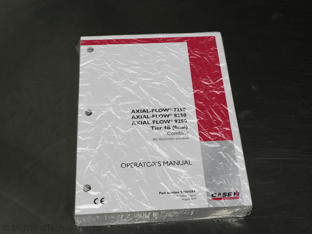
Case Axial Flow 7250, 8250, 9250, Tier 4B Combine Operator's Manual
820 pages · Publication 51564361
Added to your cart. View cart
- Models
- Axial Flow 7250, 8250, 9250, Tier 4B
- Serial coverage
- PIN YKG241001 and above
- Manual type
- Operator's Manual
- Pages
- 820
- Publication
- 51564361
- Condition
- Brand new
What's inside
From the manual's own table of contents: 183 sections, 411 entries. See sample pages (PDF, 899 KB)
Show all 183 sections
Selective Catalytic Reduction (SCR) exhaust treatment - Safety signs25 topics
- Access to operator’s platform
- Folding ladder
- Cab layout
- Emergency exit
- Operator's seat
- Seat belt – Operator’s seat
- Instructional seat – Overview
- Seat belt – Instructional seat
- Under seat cooler
- Steering column
- Emergency Stop button
- Foot controls
- Start console
- Multi-Function Handle (MFH)
- Unload tube
- Pivoting unloading spout – if equipped
- Quick stop
- Feedrate control
- AFS Accuguide™
- Automatic Header Height Control (AHHC)
- Header controls – MFH
- Reel position
- Feeder fore/aft tilt – In cab adjustment
- Grain tank unloading drive
- Shift button
Lighting and mirrors26 topics
- Engine platform access
- Side shields - Open/Close
- Service platforms and shielding
- Rotor module – Access
- Grain tank – Covers/extensions
- Grain tank - Access/Exit
- Adjustable threshing cage – Access
- Jacking points – Locations
- Selective Catalytic Reduction (SCR) exhaust treatment - Overview
- Before driving the combine
- Axial Trac
- Track Transmission Unlock
- Daily start-up procedure
- Starting the engine – Cold weather
- Engine idle speed
- Stopping the engine
- Moving the machine
- Road travel
- Operator platform extension – Removal
- Operator platform extension – Installation
- Axial Trac – Road travel
- Parking brake – Manual release
- Transmission – Manual shifting
- Transporting on a trailer – Tie downs for shipping
- Attaching a trailer
- Towing the machine
Crop setup values – Crop condition adjustment141 topics
- Home screen
- Toolbox
- Diagnostics
- Data management
- Run screens
- Automatic Crop Settings (ACS)
- Combine info
- AFS Harvest Command™– Display screens
- Performance
- Screen layout setup
- Run screen pick list
- Summery data pick list
- Cleanout control
- Service screen
- Camera - Configure
- Calibrations
- Header
- Gear position
- Multi-Function Handle (MFH) - Calibrate
- Concave opening
- Pre-sieve
- Sieves – Upper and lower sieves
- Self-leveling shoe
- Groundspeed Hydrostat
- High Pressure Relief Valve (HPRV)
- CVT Rotor
- Feeder engagement
- Rear wheel position
- Inclination sensor(s)
- Residue distribution
- Pivoting unloading spout
- Folding unload tube
- Counter knives
- Distance calibration
- Steering valve
- Chopper speed shift – Actuator
- Spreader board – Calibration
- Windrow door – Actuator
- Feeder fore/aft tilt
- Cage transport vanes
- Calibration error list
- Sieves – Pressure sensor
- Header height control overview
- Header height control – Manual mode
- Header height control – Sensitivity
- Header height control – Return To Cut (RTC) mode
- Header height control – Auto Header Height Control (AHHC)
- Header height control – Pressure float mode
- Lateral tilt
- Connecting a header
- Disconnecting a header
- Header setup
- Row Header Setup
- Platform Header Setup
- Feeding
- Rock trap
- Feeder cradle – Manual adjustment
- Feeder cradle – Angle adjustment per tire size
- Feeder drum – Adjust lower stop
- Feeder chain – Adjustment
- Feeder chain – Link removal
- Reel speed
- Feeder reverse system - Overview
- Feedrate control
- Rotor
- Rotor cage
- Module – Position overview
- Rotor cage – Position adjustment
- Rotor cage – Leveling and side shift
- Rotor cage – H–frame stop bolt adjustment
- Threshing and separation
- Suggested start up configurations for major crops
- Rotor overview
- Rotor De-slug
- AFS Harvest Command™– overview
- AFS Harvest Command™– Activation
- AFS Harvest Command™– Run screen
- AFS Harvest Command™– Basic tab
- AFS Harvest Command™– Advanced tab
- AFS Harvest Command™– Sensitivities tab
- AFS Harvest Command™– Headland tab
- AFS Harvest Command™– Status tab
- AFS Harvest Command™– Ranges tab
- AFS Harvest Command™– Operation
- AFS Harvest Command™– Sensitivity adjustment
- Cleaning – Overview
- Sieves – Removal
- Sieves – Installation
- Cleaning fan
- Automatic cleaning fan speed – If equipped
- Tailings system
- Grain storage
- Clean grain elevator drive – Change speeds
- Unloading
- Folding unload tube – Transport lock
- Residue handling
- Discharge deflector
- Straw beater
- Straw chopper – Adjustments
- Knife replacement – Chopper
- Straw chopper – Service step
- Straw chopper – Standard chopper
- Counter knives – Standard cut chopper
- Knife replacement – Standard cut counter knives
- Straw chopper – Magnacut chopper
- Knife replacement – Magnacut counter knife
- Knife replacement – Chopper
- Shear bar
- Horizontal Disc Spreader
- Residue handling – Horizontal disc spreader configuration
- Vertical impeller spreader – Position
- Vertical impeller spreader – Spread width adjustment
- Vertical impeller spreader – Manual adjustment
- Vertical impeller spreader – In cab spreader controls (if equipped)
- Center divider – Adjustment
- Spreader chutes – Manual adjustment
- Windrow door
- Windrow chute
- Chaff pan
- In cab residue mode control
- In cab residue mode control – Troubleshooting
- Residue handling – Vertical impeller spreader configuration
- Hood mounted chopper – Overview
- Initial settings
- Internal deflectors
- Chopper speed
- Counter knife
- Spreader board – Height adjustment
- Fin position
- Chaff board
- Windrow roller
- Chaff spreader - Crop setting and Straw fingers
- Windrow operation
- Counter knife – Blades
- Straw chopper
- Straw chopper frame - Replace – Sieve removal
- Troubleshooting
- Residue handling – Hood mounted chopper configuration
- Maintenance - Overview
- Torque specifications for hardware
- Torque - Standard torque data for hydraulic connections
Bubble up gear box – Oil level check32 topics
- Transmission oil level
- Final drive oil level
- Lower unloading gearbox – Oil level
- Feeder conveyor gearbox – Oil Level
- Header drive gearbox oil – Oil level
- Rotor gearbox oil
- hour grease points
- Header drive gearbox oil
- Feeder conveyor gearbox
- Transmission – Change oil
- Final drive oil – Change oil
- Lower unloading gearbox – Change oil
- Unloading elbow oil level
- Tailings gearbox
- Bubble-up gearbox oil – Change oil
- Self leveling cleaning shoe pivot
- Power Take-Off (PTO) gearbox – Oil change
- Hydraulic oil return filter – Replace
- Hydraulic charge filter – Replace
- Engine oil and filter
- Fuel prefilter/water separator
- Engine mounted fuel filter
- Engine crankcase breather filter
- Hood mounted chopper – Drive bushing service
- Fuel tank breather
- Diesel Exhaust Fluid (DEF)/AdBlue® tank vent filter
- Diesel Exhaust Fluid (DEF)/AdBlue® in-line filter – If equipped
- Tailings sensor – Lens inspection
- Diesel Exhaust Fluid (DEF)/AdBlue® in tank filter
- Hydraulic reservoir, oil, and filters
- Power Take Off (PTO) – Lube filter
- Axial Trac – Oil change
Fuse and relay box - Component identification4 topics
- Post-season
- Preseason service
- Display alarms
- GrainCam™– Alarms
Inside this manual
Real pages from this operator's manual (820 pages). Open the sample pages (PDF, 898 KB)

- Controls and operation, page 131: 3 - CONTROLS AND INSTRUMENTS
- Maintenance, page 647: 7 - MAINTENANCE
- Specifications, page 791: 9 - SPECIFICATIONS
- Color page, page 64: 2 - SAFETY INFORMATION
- Color page, page 433: 6 - WORKING OPERATIONS
- Foldout diagram: 9 - SPECIFICATIONS
This is an operator's manual
Here's how it compares to the other manual types.
Service manual
Factory repair procedures and technical information such as specifications, troubleshooting, and wiring and hydraulic diagrams, for the models and systems the manual covers. See What's inside for its topics.
Operator's manual
Safe operation, controls, maintenance schedules, lubrication points, inspections, and basic checks. Repair procedures are in the service manual.
Parts manual
Illustrated diagrams with factory part numbers for identifying components and ordering parts. Repair procedures are in the service manual.
What it's used for
Factory manual for in-house farm and construction shop use. Straightforward, complete, and easy to follow. It contains the OEM information dealership service departments and parts counters use to diagnose problems, identify components, and perform maintenance or repairs correctly.
Service shops and owner/operators who repair their own equipment
Identifying correct parts and seeing how assemblies come apart and go back together
Keeping equipment running with less downtime
Factory manual, 820 pages
Quantity one is the manual described above.
Fast free USA shipping
Ships in 1 business day.
60-day returns
Free if the mistake is ours. A manual ordered in error must come back unopened in its shrink-wrap; you pay return shipping and a 20% restocking fee applies. Return policy
Binder not included
Manuals over about 300 pages may need a standard 3-ring binder, which you can buy locally to keep the pages organized for shop use.
Questions about model, serial number, engine coverage or contents? Contact us before purchasing and we'll help confirm it's the right manual. Please verify the manual type, machine model, serial number range and engine coverage before purchasing: manuals ordered in error carry a 20% restocking fee (return policy).