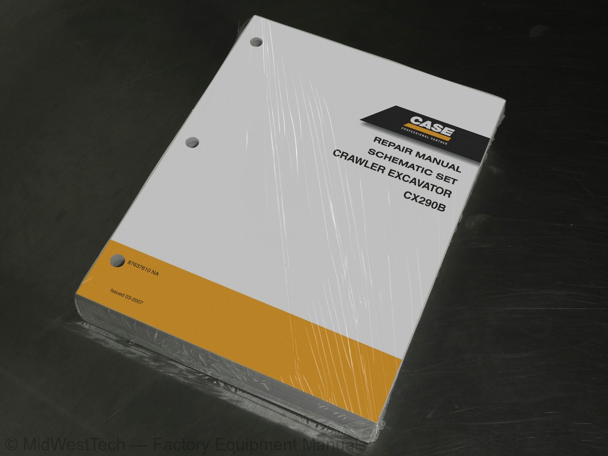
Case CX290B Schematic Set Crawler Excavator Service Manual
488 pages · Publication 87637610
Added to your cart. View cart
- Models
- CX290B Schematic Set
- Manual type
- Service Manual
- Pages
- 488
- Publication
- 87637610
- Condition
- Brand new
What's inside
From the manual's own table of contents: 242 topics. See sample pages (PDF, 1613 KB)
- Safety, General Information and Standard Torque Data
- General Specifications and Special Torque Settings
- Elecrical and Engine Functions & Service Support
- Elecrical Equipment and Electrical Circuit Diagrams
- Specifications, Troubleshooting, Checks and Hydraulic Pressure Settings
- Hydraulic Functions
- Hydraulic Component Functions
- Air Conditioner Functions and Troubleshooting
- Large Size Hydraulic Schematics
- Large Size Electrical Schematics
- AND YEAR OF MANUFACTURE OF THE MACHINE
- Machine
- Engine
- Serial numbers of the components
- FLUIDS AND LUBRICANTS
- Hydraulic fluid
- Transmission component oil
- Grease
- Engine Oil
- Fuel
- Anti-freeze/Anti-corrosion
- Environment
- Plastic and resin parts
- SPECIFICATIONS
Show all 242 topics
- Main data
- Performance
- Complete machine dimensions
- Main body dimensions
- Cooling system
- Capacity of coolant and lubricants
- Hydraulic oil filter
- Fuel filter
- Operating devices
- Hydraulic system
- Swing unit
- Travel lower body
- Work Unit
- Digging force (ISO 6015)
- COMPONENT WEIGHT
- Major component weight
- Other component weight
- SPECIAL TORQUE SETTINGS
- MACHINE OVERALL DIMENSIONS
- ELECTRIC CIRCUITS OPERATION EXPLANATION
- Explanation of Electrical Functions
- Engine Speed Control
- Throttle Control
- Idling Control (auto / one-touch)
- Idling Start
- Idle Up
- Auto Warm Up
- Engine Start / Stop Control
- Engine Start / Stop Judgment
- Power-Cut Delay
- Engine Emergency Stop
- Neutral Start
- Pump Control
- Work Mode Control
- Pump Added Horsepower Control
- Pump Horsepower Cut Control
- Power Save Control
- Swing
- Swing Brake
- Free Swing (North America Only)
- Swing Lock (for maintenance)
- Swing Relief Cut
- Travel
- Travel Speed Switchover
- Travel Alarm (North America only)
- Valve Control
- Lever Lock
- Solenoid Sticking Prevention
- Pressure Boost Control
- Monitor Control
- Bar Graph (coolant temperature gauge, oil temperature gauge, fuel gauge)
- Accessories
- Horn
- Working Light
- Wiper & Washer
- Room Lamp
- Radio Mute
- Others
- Anti-Theft
- Battery Save Function
- Alternator Power Generation Detection
- Overload Alarm (Europe only)
- Options
- Option Line Control
- Feed Pump Automatic Stop
- Return Filter Clogging Detected
- Beacon (Europe Only)
- ENGINE SUMMARY
- Engine System Diagram
- Fuel System Diagram
- Detailed Part
- Control
- are switched by the throttle volume
- With auto / one-touch switchover function
- Runs the engine at low idle speed when it starts up
- raises the low idle speed to the auto idle speed
- executed automatically when the engine starts
- Judgment based on engine speed from ECM
- OFF, 7-second delay
- recognizes this and stops the engine
- Engine start load (cell not turning) when lever locked
- and the pump horsepower is controlled
- load or sharp load
- conditions
- pump load
- is operated automatically and during travelling too
- Swing option for North America
- operations
- proportional valve and the excess oil is eliminated
- Travel speed low-speed / high-speed switchover
- Buzzer sounded (for 10 seconds) during travel
- Operation is not possible unless the gate lever is raised
- When key ON, solenoid switched ON / OFF for 0.25 second
- when necessary
- screen added to display screens, etc
- ELECTRICAL EQUIPEMENT LAYOUT DIAGRAM
- Overall View
- Main Unit Right Side Layout Diagram (radiator compartment)
- Engine Section Layout Diagram
- Main Unit Left Side Layout Diagram (pump compartment)
- Main Unit Center Section Layout Diagram
- Cab Layout Diagram 1
- Controller A
- Relay
- ECM (engine control module)
- Fuse box
- Layout Around Operator Seat
- Stand-Alone Parts Diagram
- Connection Connector Pin Layout
- Computer A
- Monitor
- ELECTRIC CIRCUIT DIAGRAM
- List of components
- Sequence Circuit Diagram (CX160B)
- Sequence Circuit Diagram (CX210B, CX240B)
- Sequence Circuit Diagram (CX290B)
- BLOC DIAGRAM
- Computer S
- ECM (Engine Control Module) (CX160B)
- ECM (Engine Control Module) (CX210B, CX240B)
- ECM (Engine Control Module) (CX290B)
- Monitor Display
- Air Conditioner
- Option
- Electrical Symbol List
- ELECTRICAL CONNECTOR WIRING DIAGRAM
- Main Frame
- Main Frame CX160B
- Main Frame CX210B, CX240B
- Main Frame CX290B
- Cab main harness
- Cab sub harness
- In cab harness
- Engine Harness
- Console
- Console Right harness
- Console Left harnes
- SPECIAL TOOLS
- Tester
- HYDRAULIC EQUIPMENT LAYOUT
- Pump chamber
- Swing body center section
- Housing left side
- IDENTIFICATION OF HYDRAULIC COMPONENTS
- Pump
- Control valve
- Way solenoid valve
- Remote control valves (upper side, travel)
- Cushion valve
- way multi-valve
- Direction valve / Shut-off valve
- Safety valve
- Manifolds
- Swing motor
- Travel motor
- Center joint
- PREPARATION BEFORE INSPECTION
- Releasing pressure in the hydraulic system and Pressure measurement preparations
- Procedures for pressure measurement from the monitor display
- Procedures for measuring hydraulic oil temperature from the monitor display
- Pressure measuring port
- PRESSURE MEASUREMENT
- Main Pressure Measurement
- Pilot pressure measurement
- Negative pressure measurement
- PRESSURE ADJUSTMENT
- Main pressure adjustment
- Pilot pressure adjustment
- List of functions
- TRAVEL CIRCUITS
- Travel Low-speed Circuit
- Travel High-Speed Circuit
- Straight Travel Circuit
- SWING CIRCUITS
- Swing Relief Cut-off Control Circuit
- Swing Priority Circuit
- Swing Brake Circuit
- Swing Parking Circuit (lever in neutral)
- Swing Parking Circuit (brake release)
- Swing Parking Circuit (machine stop)
- BOOM CIRCUITS
- Boom-Up Circuit (single operation)
- Boom-Up Circuit (compound boom-up + arm-in)
- Boom Down Regenerative Circuit
- Boom Down Tilting Prevention Circuit
- Boom Down Load Hold Valve Circuit
- ARM CIRCUITS
- Arm-Out Circuit
- Arm-In Forced Regenerative Circuit
- Arm-In Load Hold Valve Circuit
- BUCKET CIRCUITS
- Bucket Open Circuit
- Bucket Close Regenerative Circuit
- NEGATIVE CONTROL CIRCUITS
- Negative Control Circuit (power save solenoid OFF)
- Negative Control Power Save Circuit (power save solenoid ON)
- Negative Control Circuit (bucket close, power save solenoid OFF)
- HORSEPOWER BOOST CIRCUITS
- Arm-In Horsepower Boost Circuit
- Travel Horsepower Boost Circuit
- OTHER CIRCUITS
- Cushion Circuit
- Heat Circuit (lever in neutral)
- Auto Pressure Boost Circuit (bucket close)
- OPTION CIRCUITS
- Breaker Circuit (single operation)
- Shuttle Circuit (hydraulic fork)
- Combined Circuit
- Second Option Circuit (hydraulic rotation fork)
- HYDRAULIC PUMP
- Regulator
- Gear Pump
- MOTOR
- VALVE
- Stack Solenoid Valve Operation Explanation
- Upper Pilot Valve (remote control valve)
- Travel Pilot Valve (remote control valve)
- Selector Valve (3-direction valve)
Inside this manual
Real pages from this service manual (488 pages). Open the sample pages (PDF, 1612 KB)
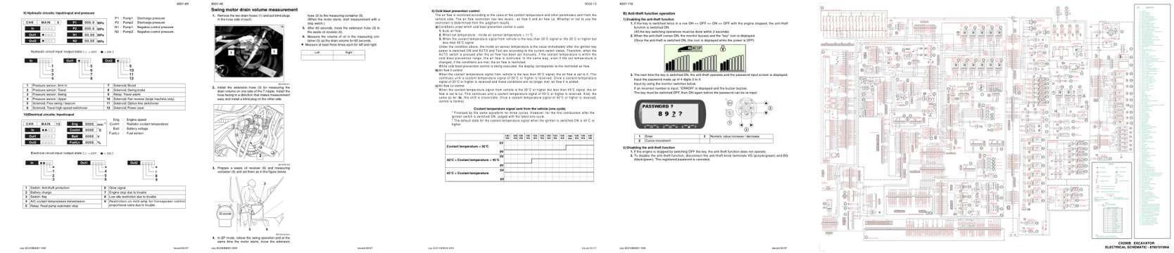
- Diagram, page 120: 9) Hydraulic circuits; Input/ouput and pressure
- Repair procedure, page 281: Lep SC290B8001-0NA
- Specifications, page 456: Lep SC210B9006-0NA
- Color page, page 147: Lep SC210B4001-1NA
- Foldout diagram (color), page 487: PLATFORM
This is a service manual
Here's how it compares to the other manual types.
Service manual
Factory repair procedures and technical information such as specifications, troubleshooting, and wiring and hydraulic diagrams, for the models and systems the manual covers. See What's inside for its topics.
Operator's manual
Safe operation, controls, maintenance schedules, lubrication points, inspections, and basic checks. Repair procedures are in the service manual.
Parts manual
Illustrated diagrams with factory part numbers for identifying components and ordering parts. Repair procedures are in the service manual.
Engine service manuals are sometimes sold separately, since certain machine models were offered with more than one engine option.
What it's used for
Factory manual for in-house farm and construction shop use. Straightforward, complete, and easy to follow. It contains the OEM information dealership service departments and parts counters use to diagnose problems, identify components, and perform maintenance or repairs correctly.
Service shops and owner/operators who repair their own equipment
Identifying correct parts and seeing how assemblies come apart and go back together
Keeping equipment running with less downtime
Factory manual, 488 pages
Quantity one is the manual described above.
Fast free USA shipping
Ships in 1 business day.
60-day returns
Free if the mistake is ours. A manual ordered in error must come back unopened in its shrink-wrap; you pay return shipping and a 20% restocking fee applies. Return policy
Binder not included
Manuals over about 300 pages may need a standard 3-ring binder, which you can buy locally to keep the pages organized for shop use.
Other editions and similar models
Questions about model, serial number, engine coverage or contents? Contact us before purchasing and we'll help confirm it's the right manual. Please verify the manual type, machine model, serial number range and engine coverage before purchasing: manuals ordered in error carry a 20% restocking fee (return policy).