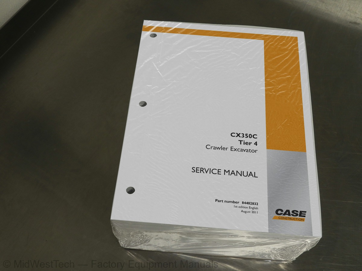
Case CX350C Tier 4 Crawler Excavator Service Manual
1,954 pages · Publication 84402832
Added to your cart. View cart
- Models
- CX350C Tier 4
- Manual type
- Service Manual
- Pages
- 1,954
- Publication
- 84402832
- Condition
- Brand new
What's inside
From the manual's own table of contents: 700 topics. See sample pages (PDF, 671 KB)
- GENERAL INFORMATION
- Safety
- ROPS Judgment Method
- Standard Torque Data For Cap Screws And Nuts
- Overall (CX350C)
- Main Data
- Performance
- Main Unit Dimensions
- Engine
- Cooling System
- Upper Side Work System
- Operating Device
- Swing Units
- Travel Lower Body
- Hydraulic Equipment
- Hydraulic Device
- Control Valve and Cylinder
- Capacities, Filters
- Coolant and Oil Capacities
- Hydraulic Oil Filters
- Fuel Filter
- Main Equipment Table
- Lower Component
- Travel Unit
Show all 700 topics
- Take-up Roller
- Upper Roller
- Lower Roller
- Recoil Spring
- Upper Component
- Swing Unit (CX350C)
- Engine-related
- Air Cleaner (double element)
- Radiator
- Hydraulic Pump
- Control-related
- Control Valve
- Solenoid Valve (4 stack)
- Remote Control Valve (left/right, travel operations)
- Remote Control Valve for Left/Right Operations
- Remote Control Valve for Travel Operations
- Remote Control Valve Characteristic Diagram
- Operation Remote Control Valve Control Diagram
- Travel Remote Control Valve Control Diagram
- Cushion Valve (heat circuit, with shuttle valve)
- Center Joint
- Backhoe Attachment
- Cylinder
- Main Unit Weight
- Divided Weight (standard specifications) CX350C
- Stand Alone Part Weight (CX350C)
- Shoe Weight (per side) CX350C
- Arm Weight (CX350C)
- Drive Sprocket
- Track Shoe (grouser shoe)
- Attachment (backhoe)
- Boom and Swing Frame Installation Section
- Boom Cylinder and Swing Frame Installation Section
- Boom and Boom Cylinder Installation Section
- Boom and Arm Cylinder Installation Section
- Boom and Arm Installation Section
- Arm and Arm Cylinder Installation Section
- Arm and Bucket Cylinder Installation Section
- Arm and Arm Link Installation Section
- Bucket and Bucket Link Installation Section
- Bucket Link and Bucket Cylinder Installation Section
- Bucket and Arm Installation Section
- Inspection Gauge
- For Drive Sprocket
- For Take-up Roller
- For Upper Roller
- For Lower Roller
- Standard Arm (3.25 m)
- Ultra-short Arm (2.21 m)
- Tools to purchase or to make locally
- Travel Motor Special Tool
- Take-up Roller Special Tool
- Upper Roller Special Tool
- Lower Roller Special Tool
- Grease Cylinder Special Tool
- Jig Dimension Diagram
- Center Joint Special Tool
- Swing Motor Special Tool
- Remote Control Valve Special Tool
- Gas Filling Special Tool
- Hydraulic Circuit
- CASE SPECIAL TOOLS
- Isuzu Engine Special Tools
- 4HK1X-6HK1X Tier 4 Isuzu Engine
- Attachment Special Tool (for Cylinder Assembly)
- Special Jigs Part Number List
- CNH-EST DIAGNOSTIC TOOL (SCAN TOOL)
- HYDRAULIC FLUID
- ENGINE OIL
- FUEL
- Conditions applicable to diesel fuel
- RECOMMENDED CONDITIONS THAT CAN BE APPLIED TO DIESEL FUEL
- Removal and Installation of Fuel Cooler
- Removal of Fuel Cooler
- Installation of Fuel Cooler
- Removal and Installation of Engine Inter Cooler
- Removal of Inter Cooler
- Installation of Inter Cooler
- Removal and Installation of Radiator
- Removal of Radiator
- Installation of radiator
- Removal and Installation of Oil Cooler
- Removal of oil cooler
- Installation of oil cooler
- Cylinder head cover Removal
- Cylinder head cover Installation
- Removal and Installation of Cylinder Head
- Cylinder head assembly Removal
- Cylinder head assembly Disassembly
- Cylinder head assembly Reassembly
- Cylinder head assembly Installation
- Cylinder head assembly Inspection
- Removal and Installation of Oil Pan
- Oil pan Removal
- Oil pan Installation
- Removal and Installation of Oil Level Switch
- Oil level switch Removal
- Oil level switch Installation
- Removal and Installation of Oil Pump Assembly
- Oil pump assembly Removal
- Oil pump assembly Disassembly
- Oil pump assembly Reassembly
- Oil pump assembly Installation
- Oil pump assembly Inspection
- Engine oil Inspection
- Removal and Installation of Oil Port Cover
- Oil port cover Removal
- Oil port cover Installation
- Removal and Installation of Water Pump Assembly
- Water pump assembly Removal
- Water pump assembly Installation
- Water pump assembly Inspection
- Removal and Installation of Thermostat
- Thermostat Removal
- Thermostat Installation
- Thermostat Inspection
- Coolant Inspection
- Drive belt Inspection
- Removal and Installation of Overheat Switch
- Overheat switch Removal
- Overheat switch Installation
- Monitor Control
- Fuel Gauge
- Coolant Temperature Gauge
- Oil Temperature Gauge
- Monitor Display Dimming
- Eco Gauge
- DPD Gauge
- Diagnostic Trouble Code Indicator
- Clock
- Fuel Economy Gauge
- Basic Operation
- Neutral Start
- Engine Start/Stop Control
- Preheating
- Throttle
- Idling Start
- Auto Idle
- One-touch Idle
- Auto Warm Up
- Quick Warm-up
- Idling Stop
- Idle up
- Travel Speed Selection
- Swing Brake
- Static Horsepower Control
- Accessories
- Working Light
- Radio Mute
- Engine Emergency Stop
- Travel Alarm
- Back/Side View Monitor
- Swing Lock
- Overload Warning
- Operability
- Swing Speed Limit
- Pressure Boost Control
- Free Swing
- Energy saving / Noise
- Swing Relief Cut
- Stroke Control
- Boom Down Energy Save
- Auto Energy Save
- Overload Reduction Control
- End Attachment
- Breaker Mode
- Crusher Mode
- Maintenance
- Anti-theft
- Service Support
- Screen Operations
- Screen Display List
- CHECK Screen List
- MACHINE STATUS
- FAULT HISTORY
- WORK HISTORY
- ENGINE HISTORY
- HYDRAULIC HISTORY
- PART NUMBER
- SETUP Screen List
- MACHINE SELECT
- PARAMETERS
- Setting
- Model Select
- Throttle Volume Default Setting
- Password Setting
- Adjusting the Clock
- Parameter Settings
- Option Flow Pressure Setting
- Screen Brightness Setting
- Frequent DPD regeneration by manual regeneration
- Long DPD regeneration time
- Engine start failure
- Engine stalling
- Engine hunting, rough idling
- Excessive white smoke in the exhaust gas
- Excessive black smoke in the exhaust gas
- Abnormal noise
- Large fuel consumption
- Large oil consumption
- Insufficient engine output
- Inspection of the monitor warning light blinking circuit system
- Inspection of the scan tool power circuit system
- Inspection of the starter circuit system
- Compression pressure inspection
- Inspection of the starting system
- Inspection of the fuel system
- Inspection of the air intake system
- Inspection of the exhaust system
- Inspection of the EGR control system
- Inspection of the glow control system
- Functional inspection of the DPD
- OBD system check
- Inspection of the monitor warning light illumination circuit system
- Removal and Installation of Glow Plug
- Glow plug Removal
- Glow plug Installation
- Glow plug Inspection
- Electrical Equipment Layout Diagram
- Main Unit Left Side Layout Diagram (radiator chamber)
- Engine Section Layout Diagram
- Main Unit Right Side Layout Diagram (pump chamber)
- Main Unit Center Section Layout Diagram
- Cab Layout Diagram 1
- Cab Layout Diagram 2
- Layout Around Operator Seat
- Stand Alone Parts Diagram
- Code table
- Overall
- Block diagram
- Computer A
- Computer B
- Monitor
- Air Conditioner
- Lever Lock
- Horn
- Working lights
- Option
- Other
- Electrical Symbol List
- Removal and Installation of Suction Control Valve
- Suction control valve Removal
- Suction control valve Installation
- Removal and Installation of Fuel filter pressure
- Fuel filter pressure sensor Removal
- Fuel filter pressure sensor Installation
- Removal and Installation of Engine coolant temperature sensor
- Engine coolant temperature sensor Removal
- Engine coolant temperature sensor Installation
- Engine coolant temperature sensor Inspection
- Removal and Installation of CKP sensor
- CKP sensor Removal
- CKP sensor Installation
- CKP sensor Inspection
- Removal and Installation of CMP sensor
- CMP sensor Removal
- CMP sensor Installation
- CMP sensor Inspection
- Removal and Installation of Oil pressure sensor
- Oil pressure sensor Removal
- Oil pressure sensor Installation
- Oil pressure sensor Inspection
- Removal and Installation of Boost sensor
- Boost sensor Removal
- Boost sensor Installation
- Removal and Installation of Boost temperature sensor
- Boost temperature sensor Removal
- Boost temperature sensor Installation
- Removal and Installation of IMT sensor
- IMT sensor Removal
- IMT sensor Installation
- Removal and Installation of Exhaust differential pressure sensor
- Exhaust differential pressure sensor Removal
- Exhaust differential pressure sensor Installation
- Exhaust differential pressure sensor Inspection
- Removal and Installation of Exhaust gas temperature sensor
- Exhaust gas temperature sensor Removal
- Exhaust gas temperature sensor Installation
- Exhaust gas temperature sensor Inspection
- Engine-side Trouble
- DTC U0001 (Flash Code 84) CAN-Bus Malfunction
- DTC P0016 (Flash Code 16) Crankshaft Position - Camshaft Position Correlation
- DTC P0045 (Flash Code 33) Turbocharger Boost Control Solenoid Circuit
- DTC U0073 (Flash Code 84) Control Module Communication Bus Off
- DTC P0087 (Flash Code 225) Fuel Rail/System Pressure - Too Low
- DTC P0088 (Flash Code 118) Fuel Rail/System Pressure - Too High
- DTC P0089 (Flash Code 151) Fuel Pressure Regulator Performance
- DTC P0091 (Flash Code 247) Fuel Pressure Regulator Control Circuit Low
- DTC P0092 (Flash Code 247) Fuel Pressure Regulator Control Circuit High
- DTC P0093 (Flash Code 227) Fuel System Leak Detected
- DTC U0101 (Flash Code 85) Lost Communication with TCM
- DTC P0102 (Flash Code 91) Mass Air Flow Circuit Low Input
- DTC P0103 (Flash Code 91) Mass Air Flow Circuit High Input
- DTC P0237 (Flash Code 32) Turbo Charger Boost Sensor Circuit Low
- DTC P0238 (Flash Code 32) Turbo Charger Boost Sensor Circuit High
- DTC U0110 (Flash Code 87) Lost Communication with VNT System
- DTC P0112 (Flash Code 22) Intake Air Temperature Sensor Circuit Low
- DTC P0113 (Flash Code 22) Intake Air Temperature Sensor Circuit High
- DTC P0117 (Flash Code 23) Engine Coolant Temperature Sensor Circuit Low
- DTC P0118 (Flash Code 23) Engine Coolant Temperature Sensor Circuit High
- DTC P0122 (Flash Code 43) Throttle Position Sensor Circuit Low
- DTC P0123 (Flash Code 43) Throttle Position Sensor Circuit High
- DTC P0182 (Flash Code 211) Fuel Temperature Sensor Circuit Low
- DTC P0183 (Flash Code 211) Fuel Temperature Sensor Circuit High
- DTC P0192 (Flash Code 245) Fuel Rail Pressure Sensor Circuit Low
- DTC P0193 (Flash Code 245) Fuel Rail Pressure Sensor Circuit High
- DTC P0201 (Flash Code 271) Injector Circuit - Cylinder 1
- DTC P0202 (Flash Code 272) Injector Circuit - Cylinder 2
- DTC P0203 (Flash Code 273) Injector Circuit - Cylinder 3
- DTC P0204 (Flash Code 274) Injector Circuit - Cylinder 4
- DTC P0205 (Flash Code 275) Injector Circuit - Cylinder 5
- DTC P0206 (Flash Code 276) Injector Circuit - Cylinder 6
- DTC P0336 (Flash Code 15) Crankshaft Position Sensor Circuit Range/Performance
- DTC P0340 (Flash Code 14) Camshaft Position Sensor Circuit
- DTC P0404 (Flash Code 45) Exhaust Gas Recirculation Control Circuit Range/Performance
- DTC P0409 (Flash Code 44) Exhaust Gas Recirculation Sensor Circuit
- DTC P0426 (Flash Code 143) Catalyst Temperature Sensor Circuit Range/Performance Sensor 1
- DTC P0427 (Flash Code 48) Catalyst Temperature Sensor Circuit Low Sensor 1
- DTC P0428 (Flash Code 48) Catalyst Temperature Sensor Circuit High Sensor 1
- DTC P0522 (Flash Code 294) Oil Pressure Sensor Circuit Low
- DTC P0523 (Flash Code 294) Oil Pressure Sensor Circuit High
- DTC P0560 (Flash Code 155) System Voltage
- DTC P0563 (Flash Code 35) System Voltage High
- DTC P0601 (Flash Code 53) Internal Control Module Memory Check Sum Error
- DTC P0602 (Flash Code 154) Control Module Programming Error
- Main Unit-side Trouble
- Diagnostic Trouble Code: 7000 P1 Pressure Sensor Signal Abnormality
- Diagnostic Trouble Code: 7001 P2 Pressure Sensor Signal Abnormality
- Diagnostic Trouble Code: 7002 N1 Pressure Sensor Signal Abnormality
- Diagnostic Trouble Code: 7003 N2 Pressure Sensor Signal Abnormality
- Diagnostic Trouble Code: 7004 Overload Pressure Sensor Signal Abnormality
- Diagnostic Trouble Code: 7005 Bottom Pressure Sensor Signal Abnormality
- Diagnostic Trouble Code: 7006 Rod Pressure Sensor Signal Abnormality
- Diagnostic Trouble Code: 7020 Upper Pressure Sensor Signal Abnormality
- Diagnostic Trouble Code: 7021 Swing Pressure Sensor Signal Abnormality
- Diagnostic Trouble Code: 7022 Travel Pressure Sensor Signal Abnormality
- Diagnostic Trouble Code: 7023 Arm-in Pressure Sensor Signal Abnormality
- Diagnostic Trouble Code: 7040 Fuel Level Sensor Signal Abnormality
- Diagnostic Trouble Code: 7041 Oil Temperature Sensor Signal Abnormality
- Diagnostic Trouble Code: 7045 Monitor Thermistor Signal Abnormality
- Diagnostic Trouble Code: 7060 Boom Angle Sensor Signal Abnormality
- Diagnostic Trouble Code: 7061 Arm Angle Sensor Signal Abnormality
- Diagnostic Trouble Code: 7063 Return Filter Clogging Pressure Switch Signal Abnormality
- (Breaker specifications)
- (Other than breaker specifications)
- Diagnostic Trouble Code: 7065 Boom-up Pilot Pressure Sensor Signal Abnormality
- Diagnostic Trouble Code: 7066 Bucket-close Pilot Pressure Sensor Signal Abnormality
- Diagnostic Trouble Code: 7200 Swing Brake Solenoid Signal Abnormality
- Diagnostic Trouble Code: 7201 Travel High-speed Solenoid Signal Abnormality
- Diagnostic Trouble Code: 7202 Pressure Boost Solenoid Signal Abnormality
- Diagnostic Trouble Code: 7203 Travel Alarm Buzzer Signal Abnormality
- Diagnostic Trouble Code: 7204 Power Save Solenoid Signal Abnormality
- Diagnostic Trouble Code: 7205 Feed Pump Relay Signal Abnormality
- Diagnostic Trouble Code: 7206 Option Line Switchover Solenoid Signal Abnormality
- Diagnostic Trouble Code: 7207 Free Swing Solenoid Signal Abnormality
- Diagnostic Trouble Code: 7210 Liftcrane Buzzer Signal Abnormality
- Diagnostic Trouble Code: 7211 Rotating Light Relay and Bucket Lock Signal Abnormality
- Diagnostic Trouble Code: 7240 Pump Horsepower Proportional Valve Signal Abnormality
- Diagnostic Trouble Code: 7241 P1 Flow Control Proportional Valve Signal Abnormality
- Diagnostic Trouble Code: 7242 Fan Proportional Valve Signal Abnormality
- Diagnostic Trouble Code: 7246 2 Pumps Flow Solenoid Signal Abnormality
- Diagnostic Trouble Code: 7247 Boom-down Proportional Valve Signal Abnormality
- Diagnostic Trouble Code: 7248 Arm-in Proportional Valve Signal Abnormality
- Diagnostic Trouble Code: 7250 Option Relief Pressure Proportional Valve Signal Abnormality
- Diagnostic Trouble Code: 7251 Battery Control Relay Signal Abnormality
- Diagnostic Trouble Code: 7252 Idle Stop Relay Signal Abnormality
- Diagnostic Trouble Code: 7253 DPD Regeneration Request Output Signal Abnormality
- Diagnostic Trouble Code: 7400 Abnormally High Coolant Temperature (105°C or higher)
- Diagnostic Trouble Code: 7401 Abnormally High Coolant Temperature (110°C or higher)
- Diagnostic Trouble Code: 7402 Abnormally High Coolant Temperature (120°C or higher)
- Diagnostic Trouble Code: 7404 Abnormally High Oil Temperature (95°C or higher)
- Main Frame
- Cab Main Harness
- Frame
- Engine and Pump
- Attachments
- Battery
- Configuration Diagram
- Dimension Diagram
- Disassembly Procedures
- Assembly Procedures
- Tools for Assembly and Disassembly
- Standard tools
- Secondary materials
- Special Tool (jig)
- Measurement device
- Motor Disassembly Procedures
- Precautions before motor disassembly
- Tightening torque
- Disassembly procedure
- Removal of supplied valves
- Disassembly of motor
- Disassembly of overload relief valve
- Reduction gear disassembly procedures
- Disassembly preparations
- Installation to receiving platform of reduction gear (unit)
- Removal of reduction gear cover
- Removal of carrier 1 assembly
- Removal of carrier 2 assembly
- Removal of housing assembly
- Disassembly of housing assembly
- Removal of floating seal from motor
- Disassembly of carrier 1 assembly
- Disassembly of carrier 2 assembly
- Maintenance standards
- Motor parts maintenance standards
- Reduction gear parts maintenance standards
- Inspection prior to reassembly
- Thrust washer
- Gears
- Bearing
- Floating seal
- Parts maintenance
- Assembly of motor
- Precautions before Motor Assembly
- Assembly procedure
- Motor Assembly Procedure
- Assembly of the carrier 2 assembly
- Assembly of the carrier 1 assembly
- Installation of bearing and floating seal
- Assembly of the housing assembly
- Determining the thickness of the angular bearing shim
- Installation of housing assembly
- Installation of carrier 2 assembly
- Installation of carrier 1 assembly
- Cover attachment
- Overall view
- PUMP CHAMBER HYDRAULIC EQUIPMENT LAYOUT
- SWING BODY CENTER SECTION HYDRAULIC EQUIPMENT
- HOUSING LEFT SIDE HYDRAULIC EQUIPMENT LAYOUT
- LAYOUT OF HYDRAULIC EQUIPMENT IN CAB
- Hydraulic Pump (standard model)
- Relief Valve
- Stack Solenoid Valve
- Remote Control Valves (upper, travel)
- Remote Control Valves (left-right)
- Remote Control Valve (travel)
- Cushion Valve
- Direction Valve/Relief Valve (electromagnetic proportional)
- Direction Valve
- Relief Valve (electromagnetic proportional)
- HBCV
- Manifold Under Cab
- Manifold (accumulator section)
- Manifold (hydraulic oil tank section)
- Swing Motor
- Travel Motor
- Procedures for Pressure Measurement from the Monitor Display
- Monitor and switch panel
- Pressure Measurement Method
- Operating Method
- PROCEDURES FOR MEASURING HYDRAULIC OIL TEMPERATURE FROM THE MONITOR DISPLAY
- Hydraulic Oil Temperature Measurement Method
- Procedures for Pressure Measurement by Installing Pressure Gauge
- Preparations
- Items to Prepare
- Pressure Measuring Ports
- Structure and Operation Explanation of Control Valve
- Location of Relief Valves
- Pressure Measurement Preparations
- Pressure Measurement
- Main Pressure Measurement
- A.Attachment pressure measurement
- Boom-down pressure measurement
- B.Travel pressure measurement
- C.Swing pressure measurement
- D.Option line pressure measurement
- Pilot Pressure Measurement
- Pressure gauge installation
- Negative Control Pressure Measurement
- Pressure Adjustment
- Main Pressure Adjustment
- Main relief pressure adjustment
- Pressure measurement and adjustment preparation work
- Overload relief pressure adjustment
- Swing relief pressure adjustment
- Pilot Pressure Adjustment
- Hydraulic Pump Flow Measurement Procedures
- Work Preparations
- Flow Measurement
- Check
- Boom Cylinder HBCV
- Arm Cylinder HBCV
- Removal of Operation Remote Control Valve (left side)
- Installation of Operation Remote Control Valve (left side)
- Removal of Operation Remote Control Valve (right side)
- Installation of Operation Remote Control Valve (right side)
- Replacement standards for worn parts
- Standards for repairing cylinders, valve plates, and swash plates (shoe plates)
- Attached diagram 1. pump assembly cross-section diagram
- Drive Shaft Front Side
- Drive Shaft Rear Side
- Part Table
- Procedures for Assembly and Disassembly of Regulator
- Tools
- Disassembly
- Cautions for disassembly
- Removal of long cap and pull out of main spool
- Disassembly of arm 1 parallel-tandem spool, neutral cut spool section
- Disassembly of arm regeneration release valve section
- Disassembly of load check valve section
- Disassembly of antidrift valve section
- Disassembly of relief valve
- Disassembly of option section
- Disassembly of straight travel signal control valve
- Disassembly of other plugs
- Disassembly of add-on section
- Disassembly of valve housing union bolt
- Cleaning
- Inspection
- Cautions for assembly
- Cautions for O-Ring handling
- Cautions for spool handling
- Procedure for assembly of sub-assembly
- Assembly of spool assembly (main spool)
- Assembly of arm 1 parallel-tandem spool assembly
- Assembly of neutral cut spool assembly
- Assembly of antidrift valve assembly
- Procedure for assembly of control valve main unit
- Assembly of relief valve
- Assembly of load check valve
- Assembly of antidrift valve
- Assembly of option section
- Assembly of arm regeneration release valve
- Assembly of arm 1 parallel-tandem spool
- Assembly of neutral cut spool
- Assembly of main spool
- Assembly of straight travel signal control valve
- Assembly of add-on section
- Assembly of other plugs
- Internal structure diagram
- Part list
- Procedures for assembly and disassembly of main relief valve
- Procedures for assembly and disassembly of overload relief valve
- Procedures for assembly and disassembly of low-pressure relief valve
- Procedures for assembly and disassembly of add-on main relief valve
- Relief valve adjustment
- Installation
- Specifications and structure diagram (including the assembly diagram and parts table)
- Basic functions
- Function of Each Location
- Cylinder Head Assembly
- Piston Assembly
- Pipe assembly
- Handling Precautions
- Precautions for Installing the Cylinder on the Machine Body
- Usage Cautions
- Maintenance and Inspection Cautions
- Maintenance Inspection and Service
- Trouble Diagnostics
- Storage Standards
- Storing Parts Individually (In principle, store indoors.)
- When Mounted on Vehicle Body
- Recommended Anti-rust Oil
- Assembly and Disassembly Procedures
- General Work Precautions
- Inspection after Assembly
- Required Tool
- General Tool
- Wrench assembly (U1)
- Piston Ring Expander
- Bushing Tool Kit
- Piston Rod Assembly
- Disassembly of piston assembly
- Disassembly of Cylinder Head Assembly
- Assembly of Piston Rod Assembly
- Assembly of Piston Assembly
- Structural Diagram
- Boom Cylinder
- Arm Cylinder
- Bucket Cylinder
- Procedures for Assembly and Disassembly of Operation Remote Control Valve
- Maintenance Procedures
- Required Tools and Tightening Torque
- Causes of Trouble and Countermeasures
- Procedures for Assembly and Disassembly of Travel Remote Control Valve
- Causes of Trouble and Countermeasures and Cross-section Diagram
- Reverse Operation Spool Section
- Check Plunger Section with Throttle
- Shuttle Valve Section
- Written Materials
- Causes of Trouble and Solutions
- Maintenance Standard Table
- Assembly
- Swing Motor Internal Structural Diagram
- Travel Circuit
- Travel low-speed circuit
- Travel high-speed circuit
- Straight travel circuit
- Straight travel circuit (with HBCV)
- Swing Circuit
- Swing speed limit control circuit
- Swing relief cut-off control circuit
- Swing priority circuit
- Swing priority circuit (with HBCV)
- Swing brake circuit
- Swing parking circuit (lever in neutral)
- Swing parking circuit (brake release)
- Swing parking circuit (machine stop)
- Boom Circuit
- Boom-up circuit (independent operation)
- Boom-up circuit (independent operation) (with HBCV)
- Boom-up circuit (compound boom-up + arm-in)
- Boom-up circuit (compound boom-up + arm-in) (with HBCV)
- Boom-down regenerative circuit
- Boom-down regenerative circuit (with HBCV)
- Boom-down tilting prevention circuit
- Boom-down tilting prevention circuit (with HBCV)
- Boom-down load holding valve circuit
- Boom-down load holding valve circuit (with HBCV)
- Arm Circuit
- Arm-out circuit
- Arm-out circuit (with HBCV)
- Arm-in forced regenerative circuit
- Arm-in forced regenerative circuit (with HBCV)
- Arm-in load holding valve circuit
- Arm-in load holding valve circuit (with HBCV)
- Bucket Circuit
- Bucket-open circuit
- Bucket-close regenerative circuit
- Negative Control Circuit
- Horsepower Boost Circuits
- Arm-in Horsepower Boost Circuit
- Travel Horsepower Boost Circuit
- Other Circuits
- Cushion circuit (arm-out operation)
- Cushion circuit (arm-out operation stopped)
- Cushion circuit (arm-out →arm-in operation)
- Heat circuit (lever in neutral)
- Auto pressure boost circuit (bucket close)
- Option Circuits
- Breaker circuit (independent operation)
- Double-acting circuit (hydraulic fork)
- Multi-purpose circuit (breaker Q control)
- Multi-purpose circuit (2 pumps flow crusher)
- 2nd option circuit (hydraulic rotation fork)
- Structure and operation explanation
- Hydraulic Pump Internal Structure Diagram
- Gear Pump
- Gear pump internal structure diagram
- Travel motor operation explanation
- Structure
- Summary explanation of component parts
- Rotary group
- Parking Brake
- Variable Capacity Mechanism Section
- Overload Relief Valve
- Brake Valve Section
- Function
- Motor operation
- Parking Brake Operation
- Operation of Variable Capacity Mechanism Section
- Overload Relief Valve Operation
- Brake Valve Operation
- Swing Motor Operation Explanation
- Hydraulic Motor Section
- Valve Casing Section
- Brake Section
- Relief Valve Operation Explanation (relief valve model: KRD22EK10)
- Swing Motor Internal Structure Diagram
- Operation
- Pressure Reduction Valve Section
- Operating Section Damping Mechanism Section
- Air Conditioner Overall Diagram
- Equipment Layout Diagram
- Circuit Diagram
- Air Conditioner Circuit Diagram
- Explanation of Functions
- Explanation of Control
- Air Mix Motor Actuator Control
- Blow Mode Motor Actuator Control
- Refresh/Recirculate Switch Motor Actuator Control
- Blower Amp Control
- Compressor Clutch Control
- COOLMAX Control and HOTMAX Control
- Abnormality Detection and Control after Abnormality Detected
Inside this manual
Real pages from this service manual (1,954 pages). Open the sample pages (PDF, 670 KB)

- Diagram, page 981: Electrical Wiring Diagram
- Troubleshooting, page 1,131: Assembly and Disassembly of Travel Motor
- Specifications, page 1,791: Removal and Installation of Boom
- Color page, page 511: Service Support
- Color page, page 676: Part number 84541713
- Foldout diagram (color), page 1,549: Explanation of Hydraulic Circuit and Operations (standard model)
Other manuals for this machine
Save 10% on 2 manuals, 15% on 3 or more. Other manuals for the CX350C Tier 4 are listed below. Editions cover different serial number ranges: check the serial coverage and tick only the ones that match your machine.
Added to your cart. View cart
This is a service manual
Here's how it compares to the other manual types.
Service manual
Factory repair procedures and technical information such as specifications, troubleshooting, and wiring and hydraulic diagrams, for the models and systems the manual covers. See What's inside for its topics.
Operator's manual
Safe operation, controls, maintenance schedules, lubrication points, inspections, and basic checks. Repair procedures are in the service manual.
Parts manual
Illustrated diagrams with factory part numbers for identifying components and ordering parts. Repair procedures are in the service manual.
Engine service manuals are sometimes sold separately, since certain machine models were offered with more than one engine option.
What it's used for
Factory manual for in-house farm and construction shop use. Straightforward, complete, and easy to follow. It contains the OEM information dealership service departments and parts counters use to diagnose problems, identify components, and perform maintenance or repairs correctly.
Service shops and owner/operators who repair their own equipment
Identifying correct parts and seeing how assemblies come apart and go back together
Keeping equipment running with less downtime
Factory manual, 1,954 pages
Quantity one is the manual described above.
Fast free USA shipping
Ships in 1 business day.
60-day returns
Free if the mistake is ours. A manual ordered in error must come back unopened in its shrink-wrap; you pay return shipping and a 20% restocking fee applies. Return policy
Binder not included
Manuals over about 300 pages may need a standard 3-ring binder, which you can buy locally to keep the pages organized for shop use.
Other editions and similar models
Questions about model, serial number, engine coverage or contents? Contact us before purchasing and we'll help confirm it's the right manual. Please verify the manual type, machine model, serial number range and engine coverage before purchasing: manuals ordered in error carry a 20% restocking fee (return policy).