Case JX55, JX65, JX75, JX85, JX95 Tractor Service Manual
799 pages · Publication 87060401
Added to your cart. View cart
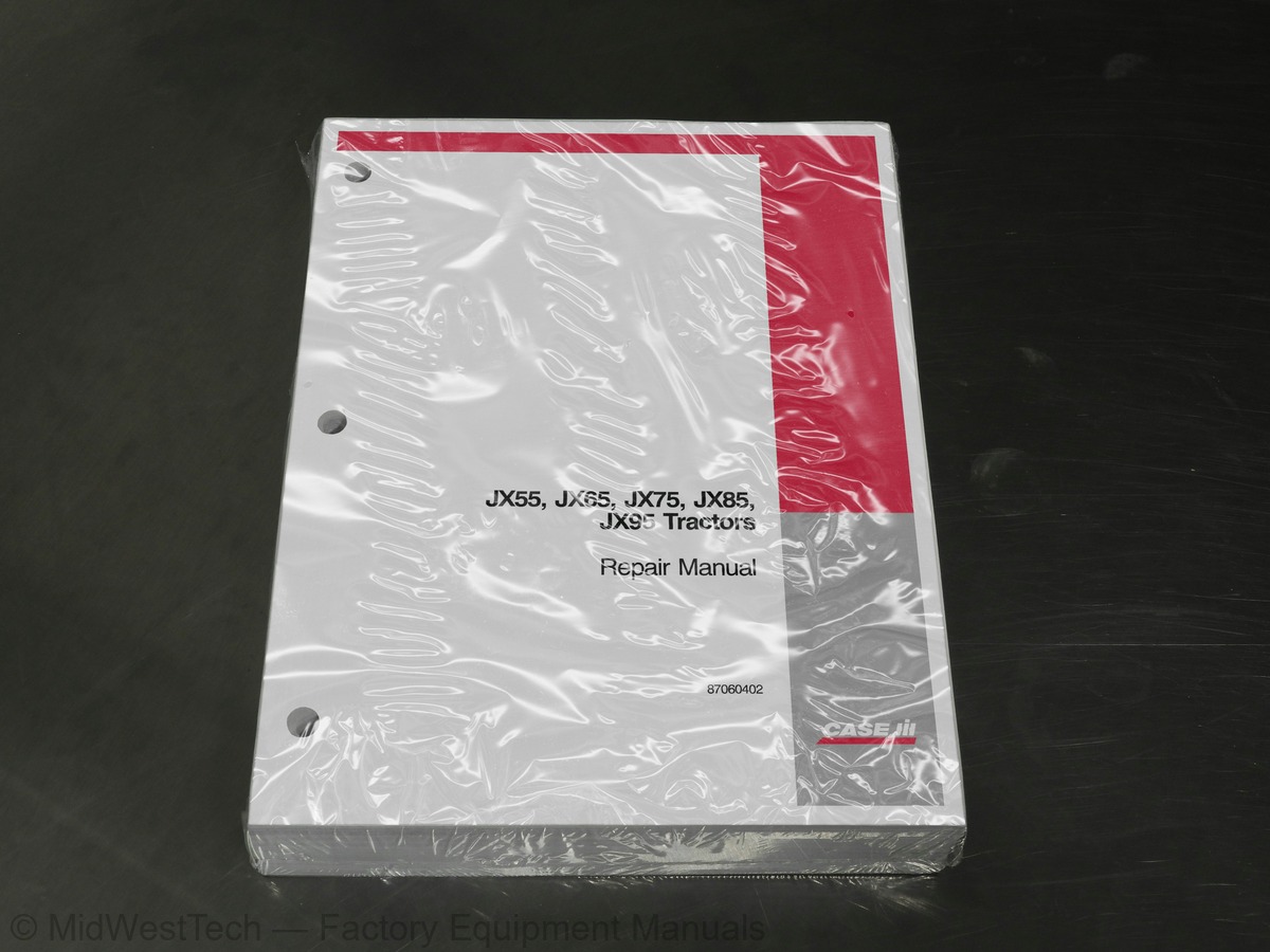
What's inside
From the manual's own table of contents: 47 sections, 300 entries. See sample pages (PDF, 545 KB)
Show all 47 sections
Overhaul37 topics
- Engine
- Removal
- Installation
- Compression Test
- Compression Ratio
- Disassembly
- Assembly
- Checks, Dimensions and Repairs
- Cylinder Block and Liners
- Crankshaft, Main Bearings and Flywheel
- Connecting Rods
- Pistons
- Camshaft, Tappets and Valves
- Cylinder Head
- Rotating Counterweight Dynamic Balancer (JX75, JX85, and JX95 Models)
- Engine Lubrication Components
- Oil Pump
- Oil Filter
- Low Oil Pressure Indicator
- Cooling System
- Radiators
- Valve Guides
- Valve Seats in Cylinder Head
- Crankshaft Front Oil Seal
- Valve Clearance
- Adjustment
- Coolant Pump and Alternator Drive Belt
- Tension Adjustment
- Water Pump
- Cooling System Thermostat
- Radiator
- Injector Sleeves
- Checking Injector Protrusion
- Fuel Injectors
- Bosch Injection Pump
- Timing
- Air Bleeding
Engine Component Overhaul12 topics
- Testing
- Fuel Injector Sleeves
- Pump Lock Timing Procedure
- Timing the Injection Pump on the Tractor
- Fuel Circuit Air Bleeding
- Turbocharged Diesel Engine
- Manifold Pressure Compensation
- Manifold Pressure Compensator (LDA)
- Description
- Operation
- Cold Start Compensation
- Mechanical Cold-start Accelerator (KSB) -- All Models
Sectional Views14 topics
- Checks, Measurements and Repairs
- Dimensions of the VALEO 11 ″ /11 ″ Dual Clutch
- Dimensions of the LUK 11 ″ /11 ″ Dual Clutch
- Dimensions of the VALEO 12 ″ /12 ″ Dual Clutch
- Dimensions of the LUK 12 ″ /12 ″ Dual Clutch
- VALEO 11 ″ Flywheel
- LUK 11 ″ Flywheel
- VALEO 12 ″ Flywheel
- LUK 12 ″ Flywheel
- Clutch Release Lever Coplanarity Adjustment
- Main Clutch Control Linkage Adjustment
- PTO Clutch Linkage Adjustment
- Synchronizer Reverser
- Gearbox/Reduction Unit
Synchronizer Reverser Troubleshooting9 topics
- Clutch--Reverser Casing
- Synchronizer Reverser--Creeper Unit
- Creeper Unit
- Gearbox
- Clutch Casing--Synchronizer Reverser and Creeper Unit
- Drive Shaft
- Transmission Shafts and Guard
- Drive Gear Housing Assembly
- Transfer Box, Unit Removed
Description of Operation11 topics
- Sectional Views
- Complete Front Axle Assembly
- Front Axle -- JX55 and JX65 Models
- Front Axle -- JX75, JX85, and JX95 Models
- Steering Knuckle Pins and Bearings
- Replacement
- Front Axle Differential
- Backlash Between Side and Planetary Pinion Teeth
- Limited--Slip, Self--locking Differential Lock
- Front Axle Differential With Limited--slip Unit
- Front Axle Differential With No Spin
Adjustments22 topics
- Stub Axle
- Wheel Hub Bearing
- Adjustment of the Preload of the Pinion Shaft Bearings
- Adjustment Shim
- Backlash Between the Pinion and Differential
- Toe--in Adjustment
- Pinion and Differential
- Final Drives
- Rear Axle Transmission -- Gearbox Case
- Transmission--Gearbox Case
- Gearbox Driving Shaft Axial Clearance
- Differential Lock Engagement Sleeve Position Adjustment
- Pinion Shaft Positioning Adjustment Ring
- Taper--Roller Bearings for Pinion Shaft
- Differential Bearings and Backlash of Ring and Pinion Teeth
- Differential Planetary and Side Gear Backlash
- 540/750 Mechanical PTO
- Right Hand or Left Hand Brake (Service Brakes)
- Front Brake Master Cylinder (Optional)
- Air Bleeding (Optional)
- Height of Service Brake Pedals
- Hand Brake Control Travel
Hydraulic System -- Description and Operation31 topics
- Table 1. Hydraulic Oil Specification
- Table 2. Hydraulic System Configuration
- Hydraulic System Diagrams
- Auxiliary (Rear) Control Valves
- Double-Acting Cylinder Lift Phase
- Double-Acting Cylinder Lower Phase
- Single-Acting Cylinder Lift Phase
- Single-Acting Cylinder Lower Phase
- Double-Acting Cylinder with Automatic Detent Release Lift Phase
- Double-Acting Cylinder with Automatic Detent Release Lower Phase
- Rear Remote Valve Control Levers
- Table 3. Control Lever Positions
- Quick-Release Couplers
- Switching Between Single and Double Acting Cylinders
- Mechanically Controlled Hydraulic Lift
- Fast Raise/Lower Control Device
- Principles of Draft Control
- Principles of Position Control
- Principles of Float
- Principles of Draft and Position Control Combined
- Hydraulic Lift Oil Flow (Lift Phase)
- Hydraulic Lift Oil Flow (Neutral Phase)
- Hydraulic Lift Oil Flow (Lowering Phase)
- Three-Point Hitch (Category I and II)
- Adjustments
- Lift Pressure Relief Valve
- Calibration
- Lift Control Valve Block
- High-pressure (Lift) Pump
- Inspection and Repair
- Convertible Single/Double Acting Auxiliary Control Valve
Components8 topics
- Hydrostatic Power Steering (2WD)
- Hydrostatic Power Steering (MFD)
- Steering Right
- Steering Left
- Manual Steering to Right
- Manual Steering to Left
- Hydrostatic Steering Control Valve
- Steering Control Valve Testing
41 206 20 Hydrostatic Steering Pump5 topics
- Steering Cylinder (2WD)
- Steering Cylinder (MFD)
- Front Axle
- Axle Wheel Hub
- Toe-in
Instrument Cluster Description5 topics
- Analog Instrument Panel
- Warning and Indicator Lights
- Fuel Level Gauge
- Tachometer and Hourmeter
- Engine Coolant Temperature Gauge
Electrical Components Description41 topics
- Instrument Console Controls
- Lights Control Lever
- Rear Hood Controls
- Starter Switch
- Cab Controls
- Fender Mounted Controls
- Heating and Air Conditioning Controls
- Radio (where applicable)
- Transmitters and Switches
- Locations
- Starting System Test on Tractor
- Power Absorption in Starter Motor Circuit
- Resistance in Ignition System Circuit (Voltage Drop)
- Battery Positive Cable Check
- Starter Motor Ground Lead Check
- Battery Ground Cable Check
- Starter Motor Tests and Inspections
- Armature Shaft End-Play
- Starter Motor Test Without Load
- Armature
- Field Windings
- Bearing Bushings
- Driving Pinion
- Precautions
- Preliminary Checks
- Tests and Checks
- Alternator Wire Connections
- Charging Current and Regulated Voltage
- Charging Circuit Voltage Drop
- Alternator Maximum Output
- Alternator
- Alternator Component Testing
- Repair
- Battery
- Battery Maintenance
- Relative Density
- Dry-Charged Batteries
- Charging the Battery
- Fuses
- Symbols Used In Electrical Circuits
- Electrical Wire Color Coding
Main Wiring Diagrams A, B, C, & D (With Cab & Less Cab)13 topics
- Diagram A (Main Harness)
- Diagram B (Dash Harness)
- Diagram C (Rear Harness)
- Diagram D (Cab/Platform Harness)
- Start-Up Circuit
- HIgh and Low Beam Headlights, Cornering and Parking Lights
- Direction Indicators and Hazard Lights Circuit
- Work Lamp Circuit
- Operator’s Presence Circuit
- Analogue Instrument Circuit
- Electrical Diagram Symbols
- Wire Color Coding
- Fuse Box/Fuses
Main Wiring Diagrams (Cab or ROPS)45 topics
- Diagrams A, B, C and D
- Individual Circuits
- Analog Instrument Circuit
- Heating and Air-Conditioning System Circuit
- Control Levers, Seat, Electrical Controls
- Rear Window, Handle and Lock
- Lock and Exterior Handle
- LH Door
- Front Wiper Motor
- Cab Windows
- Cab Heating and Ventilation Controls
- Ventilation
- Air Filter
- Heating
- Temperature Control Knob
- Ignition Switch
- Switching on the Air Conditioning and Temperature Control
- Air Conditioning and Temperature Control Button
- Heating Control Knob
- 3--Speed Fan Control Knob
- Use of the Air Conditioning System
- Main Components of the Air Conditioning System
- SANDEN SD 7H15 Compressor
- Condenser
- Receiver/Dryer
- Thermostatic Expansion Valve
- Air Conditioner Temperature Cycling Control Switch
- Thermostatic Switch (ANTIFROST)
- Evaporator
- Low Pressure Cut-out Switch
- Combined High/Low Pressure Cut--out Switch
- System Pressure Relief Valve
- Charging Stations
- Function Testing of Cab Air Conditioning System
- Summary of the Air Conditioning System Charging Operations
- Checking for Refrigerant Leaks Using an Electronic Leak Detector
- Maintenance of the Air Conditioning System
- Air Conditioning and Heating Pipes
- Receiver--Dryer
- Compressor
- Compressor Oil -- Type and Quantity
- Compressor Drive Belt
- Fitting the Compressor Drive Belt
- Checking Compressor Drive Belt Tension
- Periodic Checking of Drive Belt
Inside this manual
Real pages from this service manual (799 pages). Open the sample pages (PDF, 544 KB)
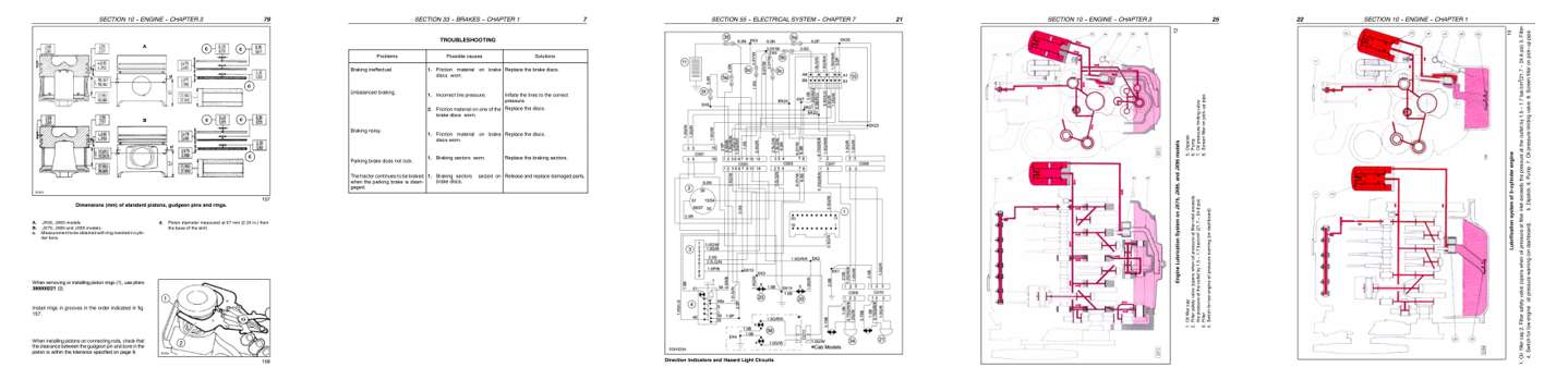
- Specifications, page 262: SECTION 10 -- ENGINE -- CHAPTER 3
- Troubleshooting, page 490: SECTION 33 -- BRAKES -- CHAPTER 1
- Diagram, page 730: SECTION 55 -- ELECTRICAL SYSTEM -- CHAPTER 7
- Color page: SECTION 10 -- ENGINE -- CHAPTER 3
- Color page: SECTION 10 -- ENGINE -- CHAPTER 1
Other manuals for this machine
Save 10% on 2 manuals, 15% on 3 or more. Other manuals are listed below. Editions cover different serial number ranges: check the serial coverage and tick only the ones that match your machine.
Added to your cart. View cart
This is a service manual
Here's how it compares to the other manual types.
Service manual
Factory repair procedures and technical information such as specifications, troubleshooting, and wiring and hydraulic diagrams, for the models and systems the manual covers. See What's inside for its topics.
Operator's manual
Safe operation, controls, maintenance schedules, lubrication points, inspections, and basic checks. Repair procedures are in the service manual.
Parts manual
Illustrated diagrams with factory part numbers for identifying components and ordering parts. Repair procedures are in the service manual.
Engine service manuals are sometimes sold separately, since certain machine models were offered with more than one engine option.
What it's used for
Factory manual for in-house farm and construction shop use. Straightforward, complete, and easy to follow. It contains the OEM information dealership service departments and parts counters use to diagnose problems, identify components, and perform maintenance or repairs correctly.
Service shops and owner/operators who repair their own equipment
Identifying correct parts and seeing how assemblies come apart and go back together
Keeping equipment running with less downtime
Factory manual, 799 pages
Quantity one is the manual described above.
Fast free USA shipping
Ships in 1 business day.
60-day returns
Free if the mistake is ours. A manual ordered in error must come back unopened in its shrink-wrap; you pay return shipping and a 20% restocking fee applies. Return policy
Binder not included
Manuals over about 300 pages may need a standard 3-ring binder, which you can buy locally to keep the pages organized for shop use.
Other editions and similar models
Questions about model, serial number, engine coverage or contents? Contact us before purchasing and we'll help confirm it's the right manual. Please verify the manual type, machine model, serial number range and engine coverage before purchasing: manuals ordered in error carry a 20% restocking fee (return policy).