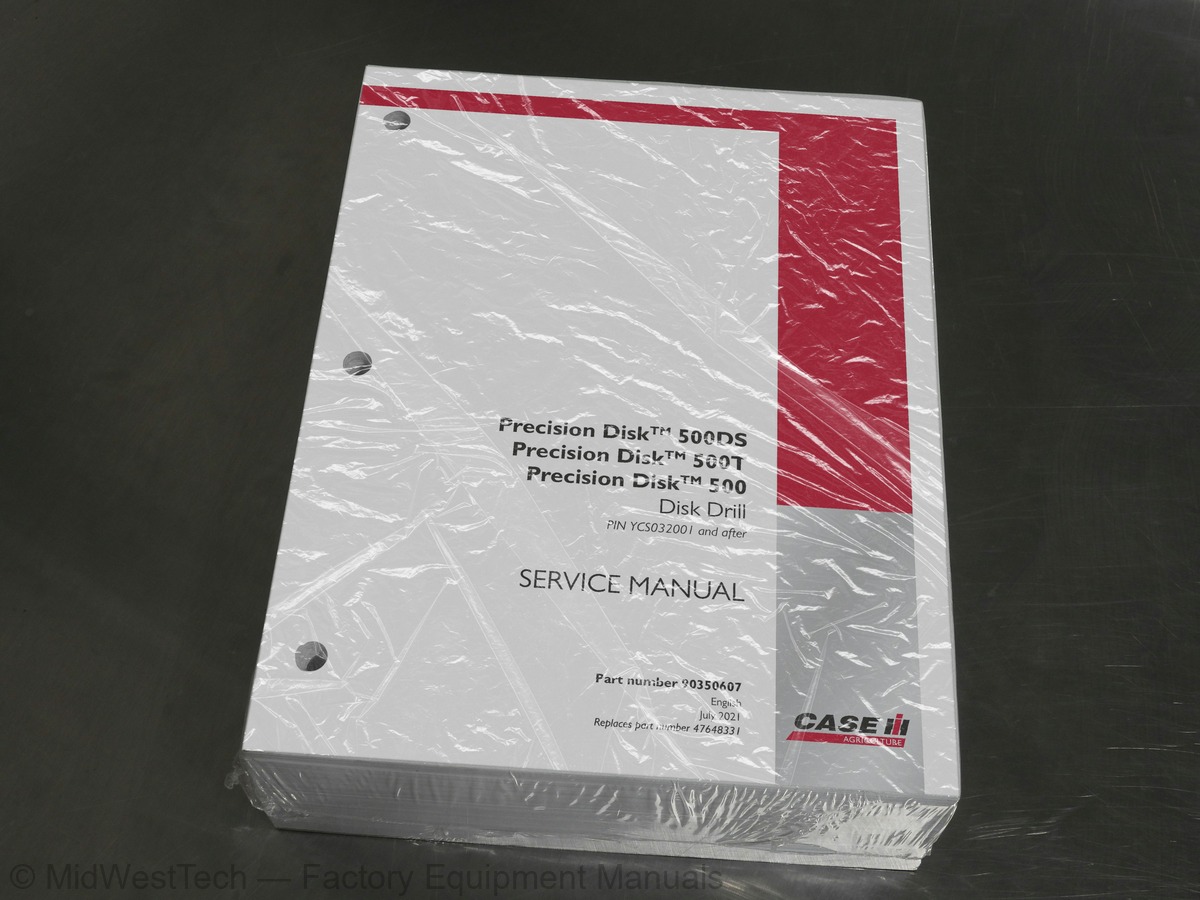
Case Precision Disk 500DS, 500T, 500 Disk Drill Service Manual
1,227 pages · Publication 90350607
Added to your cart. View cart
- Models
- Precision Disk 500DS, 500T, 500
- Serial coverage
- PIN YCS032001 and after
- Manual type
- Service Manual
- Pages
- 1,227
- Publication
- 90350607
- Condition
- Brand new
What's inside
From the manual's own table of contents: 254 topics. See sample pages (PDF, 635 KB)
- Hydraulic systems
- Reservoir, cooler, and filters
- Seeding and planting hydraulic circuits
- Metering system hydraulic circuit
- Hydraulic seeding fan system
- Frame positioning lifting
- Hitches, drawbars, and implement couplings
- Drawbars and towing hitches
- Wheels
- Front wheels
- Rear wheels
- Electrical systems
- Electrical system
- Hydraulic system control
- Harnesses and connectors
- Light harnesses
- Seeding control system
- Cab seeding controls
- Electronic modules
- FAULT CODES
- Metering system
- Product metering
- Seeding
- Product handling and delivery drive system
Show all 254 topics
- Seeding fan system
- Foreword
- Foreword - Important notice regarding equipment servicing
- Variable displacement pump - Safety rules (*)
- Safety rules
- Hand signals
- Safety signs (*)
- Safety signs - Disk drill with mounted tank (*)
- Safety rules - Ecology and the environment
- Basic instructions - Important notice regarding equipment servicing
- Torque
- Torque - Standard torque data for hydraulic connections
- Basic instructions - Measuring voltages
- Basic instructions - Up to PIN YMS091000
- Basic instructions - PIN YMS096001 and after
- Basic instructions - Electrical testing - Connector inspection
- Basic instructions - Electrical testing - Measuring voltage
- Basic instructions - Electrical testing - Measuring resistance
- Basic instructions - Electrical testing - Measuring continuity (resistance)
- Basic instructions - Electrical testing - Short circuit to ground
- Basic instructions - Electrical testing - Short circuit to high - Unwanted power
- Basic instructions - Electrical testing - Short circuit pin to pin
- Basic instructions - Electrical testing - Testing voltage
- Basic instructions - Electrical testing - Continuity test - Open circuit
- Abbreviation
- General specification - Disk drill (*)
- General specification - Disk drill with mounted tank (*)
- Hydraulic contamination
- Capacities - tank capacity (*)
- Product identification disk drill with mounted tank (*)
- Product identification disk drill (*)
- Product identification disk drill - secondary embossed serial number location (*)
- Seeding and planting hydraulic circuits - Remove oil filter (PIN YJS077001 and after)
- and after)
- Seeding and planting hydraulic circuits - Inspect oil filter components (PIN YJS077001 and after)
- after)
- Seeding and planting hydraulic circuits - Install oil filter (PIN YJS077001 and after)
- General specification - subbar and pressure valve block
- General specification - frame control valve
- General specification - meter and fan control valve (*)
- General specification - meter and fan control valve-(PIN YHS075001 and after) (*)
- Overview - disk drill (*)
- Hydraulic systems - Component localization - disk drill (*)
- Hydraulic systems - Component diagram 02 - disk drill (*)
- Hydraulic systems - Overview - disk drill with mounted tank (*)
- Hydraulic systems - Component localization - disk drill with mounted tank (*)
- Hydraulic systems - Component diagram 01 - disk drill with mounted tank (*)
- Component diagram 01 - disk drill with mounted tank-(PIN YDS042279 and after) (*)
- Hydraulic systems - Hydraulic symbol
- Hydraulic schematic frame 01 - subbar and pressure valve block
- Hydraulic schematic frame 01 - subbar and pressure valve block-(PIN YLS090073 and after)
- Hydraulic schematic frame 02 - meter control block (*)
- Hydraulic schematic frame 02 - meter control block - (PIN YDS042279 and after) (*)
- Hydraulic schematic frame 03
- Hydraulic schematic frame 05 (*)
- Hydraulic schematic frame 06 - wing lift valve block
- Dynamic description
- Dynamic description - disk drill with mounted tank (*)
- Dynamic description - down pressure - (Up to PIN YMS091000)
- Dynamic description - down pressure - (PIN YMS096001 and after)
- Dynamic description - down pressure - (PIN YDS042279 to YMS091000)
- Control valve - Remove valve block (PIN YHS075001 and after) (*)
- Control valve - Disassemble pressure control valve (PIN YHS075001 and after) (*)
- Control valve - Disassemble proportional flow control (PIN YHS075001 and after) (*)
- Control valve - Disassemble pressure compensator (PIN YHS075001 and after) (*)
- Control valve - Disassemble check valve (YHS075001 and after) (*)
- Control valve - Disassemble screen cartridge (PIN YHS075001 and after) (*)
- Control valve - Disassemble orifice 3 plug (PIN YHS075001 and after) (*)
- Control valve - Disassemble orifice 2 plug (PIN YHS075001 and after) (*)
- Control valve - Inspect valve components (PIN YHS075001 and after) (*)
- Control valve - Assemble pressure control valve (PIN YHS075001 and after) (*)
- Control valve - Assemble proportional flow control (PIN YHS075001 and after) (*)
- Control valve - Assemble pressure compensator (PIN YHS075001 and after) (*)
- Control valve - Assemble check valve (PIN YHS075001 and after) (*)
- Control valve - Assemble screen cartridge (PIN YHS075001 and after) (*)
- Control valve - Assemble orifice 3 plug (PIN YHS075001 and after) (*)
- Control valve - Assemble orifice 2 plug (PIN YHS075001 and after) (*)
- Control valve - Install valve block (PIN YHS075001 and after) (*)
- Remove the meter drive guard (*)
- Remove the meter drive roller chain (*)
- Remove the motor hydraulic hoses (*)
- Remove the meter motor drive shaft (*)
- Remove the meter motor (*)
- Disassemble the speed sensor (*)
- Disassemble the motor shaft seals (*)
- Disassemble the meter motor cover (*)
- Inspect the meter motor speed sensor, cover, and motor shaft seals (*)
- Assemble the speed sensor (*)
- Assemble the motor shaft seals (*)
- Assemble the meter motor cover (*)
- Remove (*)
- Disassemble (*)
- Assemble (*)
- Tighten - Shaft seal (*)
- Replace (*)
- Remove subbar cylinder
- Disassemble subbar cylinder
- Visual inspection subbar cylinder
- Assemble subbar cylinder
- Install subbar cylinder
- Remove 3-section wing fold cylinder (*)
- Disassemble 3 section wing fold cylinder (*)
- Assemble 3 section wing fold cylinder (*)
- Install 3-section wing fold cylinder (*)
- Remove 12.2 m (40 ft) wing fold cylinder (*)
- Disassemble 12.2 m (40 ft) wing fold cylinder (*)
- Assemble 12.2 m (40 ft) wing fold cylinder (*)
- Install 12.2 m (40 ft) wing fold cylinder (*)
- Remove 5 section inner wing fold cylinder (*)
- Disassemble 5 section inner wing fold cylinder (*)
- Assemble 5 section inner wing fold cylinder (*)
- Install 5 section inner wing fold cylinder (*)
- Remove 5 section intermediate wing fold cylinder (*)
- Disassemble 5 section intermediate wing fold cylinder (*)
- Assemble 5 section intermediate fold cylinder (*)
- Install 5 section intermediate wing fold cylinder (*)
- Remove 5 section outer wing fold cylinder (*)
- Disassemble 5 section outer wing fold cylinder (*)
- Assemble 5 section outer wing fold cylinder (*)
- Install 5 section outer wing fold cylinder (*)
- Rear wheels - Tire pressure
- General specification
- Wheel bolt torque
- Disassemble front dual walking frame wheels
- Axle wheel hub - Disassemble single front caster
- Service instruction Caster Hub and Spindle Maintenance
- Assemble front dual walking frame wheels
- Assemble single front caster
- s - Torque
- Disassemble high flotation option
- Wheel hub - Disassemble single rear tire
- Wheel hub - Disassemble rear walking beam
- Front wheels - Service instruction Caster Hub and Spindle Maintenance
- Wheel hub - Assemble - high flotation option
- Assemble single rear tire
- Assemble rear walking beam
- Overview - disk drill - (Up to PIN YDS034000) (*)
- Overview - disk drill - (PIN YMS096001 and after) (*)
- Seeding control system - Overview - mounted tank disk drill - (Up to PIN YMS091000) (*)
- Overview - mounted tank disk drill - (PIN YMS096001 and after) (*)
- Service instruction
- Technical Data Tank low sensor
- Technical Data Weigh scale load cell (*)
- Technical Data Blockage sensor (mounted tank)
- Technical Data GPS speed
- Technical Data Fan pressure
- Technical Data Work switch pressure sensor and down pressure sensor
- Technical Data Valve coil, down pressure and fan solenoid
- Technical Data clutch
- Electronic schema - drill harness
- Electrical schematic sheet 01 Schematic legend
- Electrical schematic sheet 02 Frame 1 - power connections - (Up to PIN YMS091000)
- Electrical schematic sheet 03 Frame 2 - main schematic - hydraulic valve and pressure sensors
- Electrical schematic sheet 04 Frame 3 - main schematic - CAN buses
- Electrical schematic sheet 05 Mounted tank option clutches and motor (*)
- Electrical schematic sheet 06 Frame 5 - main schematic - mounted tank option sensors (*)
- Electrical schematic sheet 07 Frame 6 - main schematic - mounted tank option (*)
- Electrical schematic sheet 08 Tow behind extension (*)
- Electrical schematic sheet 09 Splice table - main schematic
- Electrical schematic sheet 02 Frame 1 - flow 12_16_12 - power connections (*)
- Electrical schematic sheet 03 Frame 2 - flow 12_16_12 - CAN bus (*)
- Electrical schematic sheet 04 Frame 3 - flow 12_16_12 center 16, rows 1 to 8 (*)
- Electrical schematic sheet 08 Splice table - flow 12_16_12 (*)
- General specification - meter clutch (*)
- Configure inline sensors (*)
- Dynamic description (*)
- Cab seeding controls - Component diagram 00 (*)
- Detailed view (*)
- Electrical schema (*)
- Component diagram 01 (*)
- Component diagram 02 (*)
- Component diagram 04 (*)
- Component diagram 05 (*)
- Warning Alarms
- Warning Faults
- Check Signal monitor
- Check System information
- Control Reset
- Check Move display
- Check Restore factory defaults
- Check faults
- Remove Weigh scale controller (*)
- Inspect Weigh scale controller (*)
- Install Weigh scale controller (*)
- Remove Weigh scale display (*)
- Inspect Weigh scale display (*)
- Install Weigh scale display (*)
- Remove Load cell sensors (*)
- Inspect Load cells (*)
- Install Load cells (*)
- Electronic control - Problem solving - (Up to PIN YHS068000)
- Problem solving - (PIN YMS096001 and after)
- Problem solving
- 200 - Communications Error @ Flow ECU [Flow Gateway ECU] (*)
- 201 - Flow ECU is not communicating [Flow ECU] (*)
- 204 - Flow Bus Power Below Normal [Flow Gateway ECU] (*)
- 205 - Switched 12V Short! Optical Sensors [Flow Gateway ECU] (*)
- 211 - Optical sensor shorted to high source Optical Sensors [Flow ECU] (*)
- 520193-03 - ECU_PWR, Voltage above normal, or shorted to high source [Disk Drill Rate ECU]
- 520193-04 - ECU_PWR, Voltage below normal, or shorted to low source [Disk Drill Rate ECU]
- 520194-03 - Sensor Pwr, Voltage above normal, or shorted to high source [Disk Drill Rate ECU]
- 520194-04 - Sensor Pwr, Voltage below normal, or shorted to low source [Disk Drill Rate ECU]
- 520195-03 - PWR, Voltage above normal, or shorted to high source [Disk Drill Rate ECU]
- 520195-04 - PWR, Voltage below normal, or shorted to low source [Disk Drill Rate ECU]
- 520196-03 - Internal 5V, Voltage above normal, or shorted to high source [Disk Drill Rate ECU]
- 520196-04 - Internal 5V, Voltage below normal, or shorted to low source [Disk Drill Rate ECU]
- 520197-03 - Internal 8V, Voltage above normal, or shorted to high source [Disk Drill Rate ECU]
- 520197-04 - Internal 8V, Voltage below normal, or shorted to low source [Disk Drill Rate ECU]
- 520199-03 - Internal 5V, Voltage above normal, or shorted to high source [Disk Drill Rate ECU]
- 520199-04 - Internal 5V, Voltage below normal, or shorted to low source [Disk Drill Rate ECU]
- 520200-03 - +5V, Voltage above normal, or shorted to high source [Disk Drill Rate ECU]
- YMS096001 and after) [Disk Drill UCM]
- 520200-04 - +5V, Voltage below normal, or shorted to low source [Disk Drill Rate ECU]
- Seeding tool
- Air distribution system
- Dynamic description Single Shoot (SS) drills (*)
- Dynamic description Double Shoot (DS) drills (*)
- Check seed flap
- Adjust scraper
- Grease
- Remove
- Inspect
- Install
- Check
- Troubleshooting
- Static description (*)
- Exploded view (*)
- Overview mounted tank air and product flow (*)
- Flow test (*)
- Troubleshooting (*)
Inside this manual
Real pages from this service manual (1,227 pages). Open the sample pages (PDF, 635 KB)

- Diagram, page 574: CONNECTOR X-311 - ROW_C6
- Specifications, page 718: Wire connectors - Component diagram 45 Connector X-450 to X-459
- Troubleshooting, page 970: Electrical systems - FAULT CODES
- Color page, page 839: Electrical systems - Seeding control system
- Color page, page 196: Hydraulic systems - Seeding and planting hydraulic circuits
- Foldout diagram (color), page 500: Electrical systems - Harnesses and connectors
Other manuals for this machine
Save 10% on 2 manuals, 15% on 3 or more. Other manuals for the 500 are listed below. Editions cover different serial number ranges: check the serial coverage and tick only the ones that match your machine.
Added to your cart. View cart
This is a service manual
Here's how it compares to the other manual types.
Service manual
Factory repair procedures and technical information such as specifications, troubleshooting, and wiring and hydraulic diagrams, for the models and systems the manual covers. See What's inside for its topics.
Operator's manual
Safe operation, controls, maintenance schedules, lubrication points, inspections, and basic checks. Repair procedures are in the service manual.
Parts manual
Illustrated diagrams with factory part numbers for identifying components and ordering parts. Repair procedures are in the service manual.
Engine service manuals are sometimes sold separately, since certain machine models were offered with more than one engine option.
What it's used for
Factory manual for in-house farm and construction shop use. Straightforward, complete, and easy to follow. It contains the OEM information dealership service departments and parts counters use to diagnose problems, identify components, and perform maintenance or repairs correctly.
Service shops and owner/operators who repair their own equipment
Identifying correct parts and seeing how assemblies come apart and go back together
Keeping equipment running with less downtime
Factory manual, 1,227 pages
Quantity one is the manual described above.
Fast free USA shipping
Ships in 1 business day.
60-day returns
Free if the mistake is ours. A manual ordered in error must come back unopened in its shrink-wrap; you pay return shipping and a 20% restocking fee applies. Return policy
Binder not included
Manuals over about 300 pages may need a standard 3-ring binder, which you can buy locally to keep the pages organized for shop use.
Questions about model, serial number, engine coverage or contents? Contact us before purchasing and we'll help confirm it's the right manual. Please verify the manual type, machine model, serial number range and engine coverage before purchasing: manuals ordered in error carry a 20% restocking fee (return policy).