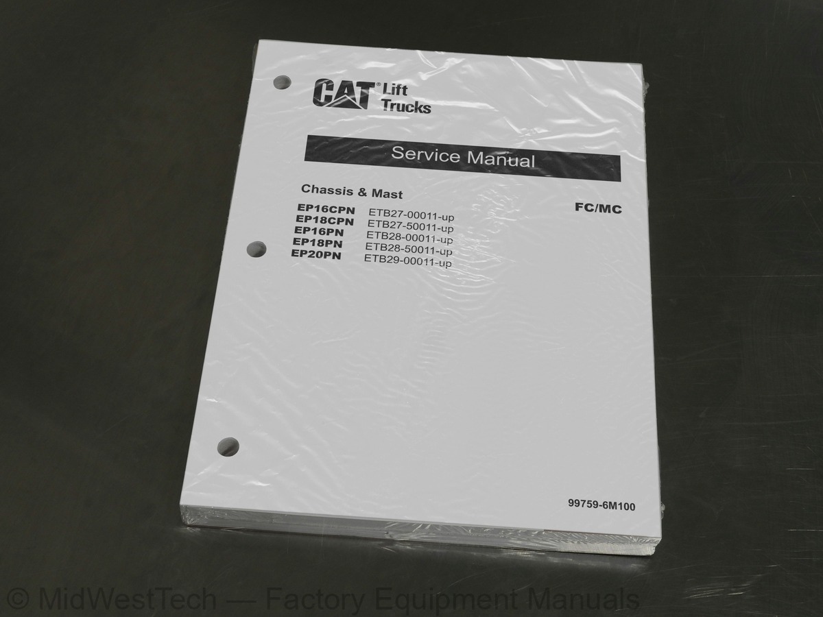
Caterpillar EP16CPN, EP18CPN, EP16PN, EP18PN, EP20PN Forklift Service Manual
317 pages · Publication 99759-6M100
Added to your cart. View cart
What's inside
From the manual's own table of contents: 215 topics. See sample pages (PDF, 316 KB)
- Model View
- Truck Models Covered
- Serial Number Locations
- Specifications
- Console
- MC Model
- FC Model
- Disassembling Console
- Disassembling Sequence
- Suggestions for Disassembly
- Reassembling Console
- Meter panel
- Functions of Meter panel
- Adjusting and Setting of Meter panel
- Error Code List
- Key Switch
- Lighting Switch (Rear Work Lamp)
- Lamps
- Specification Chart
- Horn Switch and Battery Disconnect Switch
- Troubleshooting of Lighting and Horn Systems
- Parking Brake Switch
- Combination Switch
- Direction lever
Show all 215 topics
- Light Switch, Turn Signal Switch (option)
- Disassembling Accelerator Control
- Adjusting
- Joystick Box
- Fuses
- Removing Batteries
- Removing Front Wheels
- Removing Transfer Assemblies, Traction Motors
- Installing Transfer Assemblies, Traction Motors and Calipers
- Service Data
- Structure
- External View
- Disassembling Transfer Units
- Preparation
- Disassembly Sequence
- Inspecting Transfer Units
- Reassembling Transfer Units
- Reassembly Sequence
- Rear Axle
- Steering Cylinder
- Removing Rear Wheels
- Removing Wheels
- Installing Rear Wheel
- Removing Rear Axle Assembly
- Removal Sequence
- Suggestions for Removal
- Installing Rear Axle Assembly
- Disassembling Rear Axle Assembly
- Inspection Rear Axle Assembly
- Installing Steering Cylinder and Hydraulic Pipe
- Installation Sequence
- Assembling Knuckle and Kingpin
- Assembly Sequence
- Suggestions for Reassembly
- Assembling Rear Axle Hub
- Removing Steering Sensor
- Installing Steering Sensor Assembly
- Disassembling Steering Cylinder
- Inspecting Steering Cylinder
- Reassembling Steering Cylinder
- Adjustment
- Adjusting of Steering Sensor
- Adjusting of Minimum Turning Radius
- Troubleshooting
- Outline of Brake System
- Brake Pedal Assembly
- Electro-magnetic Brake Assembly
- Removing Master Cylinder
- Disassembling Master Cylinder
- Inspecting and Adjusting Master Cylinder
- Reassembling Master Cylinder
- Inspecting and Adjusting Brake Pedal Assembly
- Manually Release of Electro-Magnetic Brake
- Parking Brake
- Brake Pedal
- Master Cylinder
- Outline of Steering System
- Removing Steering Linkage Assembly
- Inspecting Steering Linkage Assembly
- Installing Steering Linkage Assembly
- Removing PS Pump Assembly
- Installing PS Pump Assembly
- Disassembling PS Pump Assembly
- Hydraulic oil drain procedure
- Reassembling PS Pump Assembly
- Inspecting PS Pump Assembly
- PS Pump Assembly
- Reservoir Tank
- Hydraulic Line (MC Model)
- Hydraulic Line (FC Model)
- Lift and Tilt Cylinders
- Down Safety Valve
- Removing Control Valve (MC Model)
- Installing Control Valve
- Removing Gear Pump
- Installing Gear Pump
- Removing Suction Filter and Return Filter
- Installing Suction Filter and Return Filter
- Suggestions for Installation
- Removing Lift Cylinders (Simplex Mast)
- Removing Lift Cylinders (Triplex Mast and Duplex Mast)
- Installing Lift Cylinder
- Removing Tilt Cylinders
- Disassembling Lift cylinder
- Reassembling Lift Cylinder
- Disassembling Tilt Cylinder
- Reassembling Tilt Cylinder
- Inspecting and Adjusting Hydraulic System
- Hydraulic Oil
- Control Valve
- Adjusting Main Relief Valve (MC model)
- Adjusting Microswitch
- Adjusting Tilt Cylinder
- Adjusting Lift Cylinder Stroke
- Inspecting Piping
- Tests
- Vertical Drift Test
- Tilt Drift Test
- Gear Pump
- Control Valve (MC)
- Lift Cylinder
- Tilt Cylinder
- MC Control Valve
- General Description
- Hydraulic Circuit Diagram
- Hydraulic Circuit
- Structure - Inlet Cover Section
- Structure - Lift Valve
- Structure - Tilt Valve
- Construction and Function of FC Control Valve
- Outline
- FC Hydraulic System Circuit
- Bleed-off valve
- Lift Valve
- Tilt Valve
- Attachment Valve
- Removing FC Control Valve
- Installing FC Control Valve
- Disassembly of FC Control Valve
- Reassembly of FC Control Valve
- Valves Included in the Inlet Section
- Disassembling Inlet Section
- Disassembly Sequence (Part 1)
- Disassembly Sequence (Part 2)
- Disassembly Sequence (Part 3)
- Disassembly Sequence (Part 4)
- Valves Included in Tilt Section
- Disassembling Tilt Section
- Valves Incorporated in Attachment Section
- Disassembling Attachment Section
- Disassembling End Cover Plate
- Cleaning
- Inspecting
- Precautions for Reassembly
- Reassembling Inlet Section
- Reassembling Tilt Section
- Assembling Attachment Section
- Solenoid Control Valve
- Mast System
- Mast Model Code Stamping Position
- Explanation of Mast Model Code
- Mast Code and Type
- Description
- Simplex Mast (Dual-stage Panoramic Mast)
- Duplex Mast (Dual-stage Full Free Panoramic Mast)
- Triplex Mast (Triple-stage Full Free Panoramic Mast)
- Operation of Duplex Mast
- Operation of Triplex Mast
- Removing Simplex Mast
- Installing Simplex Mast
- Removing Triplex Mast, Duplex Mast
- Installing Triplex Mast, Duplex Mast
- Disassembling Simplex Mast
- Inspecting Simplex Mast
- Reassembling Simplex Mast
- Disassembling Duplex Mast
- Inspecting Duplex Mast
- Reassembling Duplex Mast
- Disassembling Triplex Mast
- Inspecting Triplex Mast
- Reassembling Triplex Mast
- Inspecting and Adjusting Mast and Forks
- Forks (all mast models)
- Chain Tension Adjustment - Simplex Mast
- Chain Tension Adjustment - Duplex Mast
- Chain Tension Adjustment - Triplex Mast
- Clearance Adjustment for Lift Bracket
- Mast Clearance Adjustment
- Main Roller Shim Replacement - Simplex Mast
- Main Roller Shim Replacement - Duplex Mast
- Main Roller Shim Replacement - Triplex Mast
- Mast Strip Adjustment
- Tilt Angle Adjustment
- Lift Cylinder Stroke Adjustment
- Simplex Mast, Duplex Mast, Triplex Mast
- Inspection Standards
- Periodic Replacement of Parts
- Critical Safety Parts
- Tightening Torques for Standard Bolts and Nuts
- Metric fine thread
- Metric coarse thread
- Lubrication Instructions
- Lubrication Chart
- Recommended Oils and Greases
- Capacity
- Weight of Major Devices
- Special tools
- Battery Exchange or Battery Charging
- Cleaning Top Roof
- Replacing Top Roof
- Maintenance
Inside this manual
Real pages from this service manual (317 pages). Open the sample pages (PDF, 315 KB)
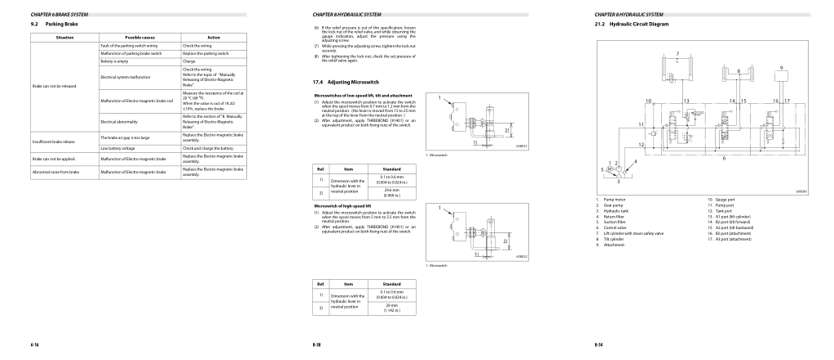
- Troubleshooting, page 127: CHAPTER 6 BRAKE SYSTEM
- Specifications, page 183: Adjusting Microswitch
- Diagram, page 199: Hydraulic Circuit Diagram
Other manuals for this machine
Save 10% on 2 manuals, 15% on 3 or more. Other manuals for the EP16CPN, EP18CPN, EP16PN, EP18PN, EP20PN are listed below. Editions cover different serial number ranges: check the serial coverage and tick only the ones that match your machine.
Added to your cart. View cart
This is a service manual
Here's how it compares to the other manual types.
Service manual
Factory repair procedures and technical information such as specifications, troubleshooting, and wiring and hydraulic diagrams, for the models and systems the manual covers. See What's inside for its topics.
Operator's manual
Safe operation, controls, maintenance schedules, lubrication points, inspections, and basic checks. Repair procedures are in the service manual.
Parts manual
Illustrated diagrams with factory part numbers for identifying components and ordering parts. Repair procedures are in the service manual.
Engine service manuals are sometimes sold separately, since certain machine models were offered with more than one engine option.
What it's used for
Factory manual for in-house farm and construction shop use. Straightforward, complete, and easy to follow. It contains the OEM information dealership service departments and parts counters use to diagnose problems, identify components, and perform maintenance or repairs correctly.
Service shops and owner/operators who repair their own equipment
Identifying correct parts and seeing how assemblies come apart and go back together
Keeping equipment running with less downtime
Factory manual, 317 pages
Quantity one is the manual described above.
Fast free USA shipping
Ships in 1 business day.
60-day returns
Free if the mistake is ours. A manual ordered in error must come back unopened in its shrink-wrap; you pay return shipping and a 20% restocking fee applies. Return policy
Binder not included
Manuals over about 300 pages may need a standard 3-ring binder, which you can buy locally to keep the pages organized for shop use.
Other editions and similar models
Questions about model, serial number, engine coverage or contents? Contact us before purchasing and we'll help confirm it's the right manual. Please verify the manual type, machine model, serial number range and engine coverage before purchasing: manuals ordered in error carry a 20% restocking fee (return policy).