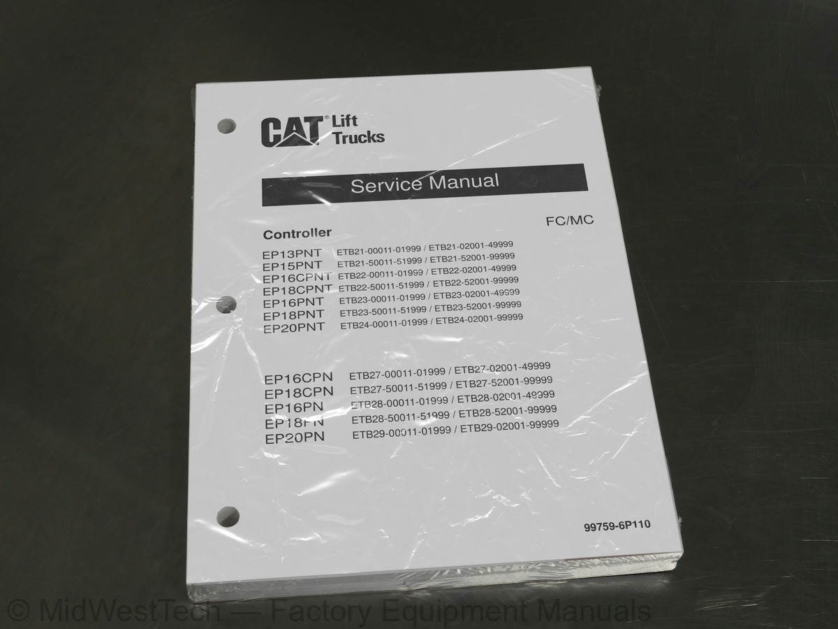
Caterpillar EP13PNT, EP15PNT, EP16CPNT, EP18CPNT, EP16PNT, EP18PNT, EP20PNT, EP16CPN, EP18CPN, EP16PN and 2 more Forklift Controller Service Manual
319 pages · Publication 99759-6P110 · EP13PNT, EP15PNT, EP16CPNT, EP18CPNT, EP16PNT, EP18PNT, EP20PNT, EP16CPN, EP18CPN, EP16PN, EP18PN, EP20PN
Added to your cart. View cart
- Models
- EP13PNT, EP15PNT, EP16CPNT, EP18CPNT, EP16PNT, EP18PNT, EP20PNT, EP16CPN, EP18CPN, EP16PN, EP18PN, EP20PN
- Serial coverage
- ETB21-00011-01999
- ETB21-02001-49999
- ETB21-50011-51999
- ETB21-52001-99999
- ETB22-00011-01999
- ETB22-02001-49999
- ETB22-50011-51999
- ETB22-52001-99999
- ETB23-00011-01999
- ETB23-02001-49999
- ETB23-50011-51999
- ETB23-52001-99999
- ETB24-00011-01999
- ETB24-02001-99999
- ETB27-00011-01999
- ETB27-02001-49999
- ETB27-50011-51999
- ETB27-52001-99999
- ETB28-00011-01999
- ETB28-02001-49999
- ETB28-50011-51999
- ETB28-52001-99999
- ETB29-00011-01999
- ETB29-02001-99999
- Manual type
- Service Manual
- Pages
- 319
- Publication
- 99759-6P110
- Condition
- Brand new
What's inside
From the manual's own table of contents: 171 topics. See sample pages (PDF, 437 KB)
- Controller System
- System Layout
- Controller Area Network (CAN)
- Outline of Logic Unit
- Outline of Inverter
- Outline of EPS Controller
- Traction Controller Feature
- Modification of Traction Characteristics
- Anti-Rollback
- Boost
- Limitation of Maximum Travel Speed
- Intuitive Speed Control
- Miscellaneous Features for Traction
- Pitching Control (Option)
- Lifting Controller Feature
- Setting and Limitation of Lift Work Speed
- Lift Stop
- Load meter (option)
- Tilt horizon (option)
- Other Feature
- PDS (Presence Detection System) Feature
- Display Function
- Parking Brake Warning Icon
- BDI (Battery Discharge Indicator) Display Features
Show all 171 topics
- Miscellaneous Features
- Hour Meter
- Setup Option
- Outline
- Details of Setup Options (Group-1)
- Details of Setup Options (Group-2)
- Details of Setup Options (Group-3)
- Setup Options (Group 1)
- Setup Options (Group 2)
- Setup Options (Group 3)
- Diagnostics
- Operation Procedure
- Self-Diagnostics
- Power Steering Diagnostics
- Run Time Diagnostics
- Fail-Safe Restriction List
- Removal and Installation
- Inverter Discharging Procedure
- Replacing Inverter
- Replacing DSP (Digital Signal Processor) Card
- Replacing Logic Unit
- Replacing EPS Controller
- Replacing Logic Card
- Replacing Power Supply Card
- Replacing FC Armrest (FC Model Only)
- Replacing Output Unit (FC Model Only)
- Basic Check
- Testing Tools
- Measurement of Card Voltage
- Checking Contactor Coil
- Checking Contactor Tips
- Checking Inverter
- Regeneration Check
- AC Motor System Basics
- Feature of AC Motor
- Speed Control of Induction Motors
- Inverter
- General Information
- Before Replacing Devices
- Connection of The Service Tool
- How to Clean Harness Connectors and System Components
- List of Diagnostic Codes
- Troubleshooting
- Traction Motor R.H.,Overheating (E0)
- Traction Motor L.H.,Overheating (E1)
- Pump Motor, Overheating (E2)
- Traction Inverter R.H., Overheating (E5)
- Traction Inverter L.H., Overheating (E6)
- Pump Inverter, Overheating (E7)
- PS Controller, Overheating (E9)
- Traction Motor Current Sensor R.H., Fault (14)
- Traction Motor R.H., Over-current (15)
- Traction Motor R.H., Stall Timer (16)
- Traction Motor Current Sensor L.H., Fault (24)
- Traction Motor L.H., Over-current (25)
- Traction Motor L.H., Stall Timer (26)
- Pump Motor Current Sensor Fault (34)
- Pump Motor Over-current (35)
- Line Contactor Fault (40)
- Steering Contactor Fault (41)
- Traction Motor R.H., Open (45)
- Traction Motor L.H., Open (46)
- Pump Motor Open (47)
- PS Motor Open (49)
- Tire Angle Sensor Fault (50)
- Accelerator Sensor Fault (51)
- Traction Motor R.H., Pulse Input Fault (52)
- Traction Motor L.H., Pulse Input Fault (53)
- FC Lever Fault (54)
- Output Unit Solenoid Fault (55)
- Output Unit Solenoid Current Leak (56)
- FNR Lever or Accelerator, Faulty Setting (E)
- Seat Switch, Faulty Setting for Traction ((E))
- Lift Lever, Faulty Setting (H1)
- Tilt Lever, Faulty Setting (H2)
- Attachment 1 Lever, Faulty Setting (H3)
- Attachment 2 Lever, Faulty Setting (H4)
- Seat Switch, Faulty Setting for Hydraulic ((L))
- FNR Lever Fault (EE)
- Display Communication Fault (60)
- Logic Card Initialize Failure (61)
- Logics Fault (62)
- Traction Inverter R.H., Fault (63)
- Traction Inverter L.H., Fault (64)
- Pump Inverter Fault (65)
- FC Armrest (67)
- Output Unit Fault (68)
- EPS Controller Fault (71)
- Contactor Coil Fault (72)
- Hydraulic Lock Solenoid Fault (74)
- Parking Brake Fault (75)
- PDS Buzzer Fault (76)
- Battery Voltage Too Low (78)
- Battery Voltage Too High (79)
- Battery Consumption Too Much (Lo)
- Tilt Angle Sensor Fault (80)
- Load Sensor Fault (81)
- Handle Sensor Fault (82)
- PS Motor Current Sensor Fault (A4)
- PS Motor Over-current (A5)
- PS Handle Brake Fault (A7)
- Battery Side Way Exchange Interlock (A8)
- Parking brake warning (A9)
- Battery Consumption Much
- Brake Oil, Low Level
- RTC Battery Low
- Motor Installation Positions
- Specifications
- Structures
- Traction motor
- Pump motor
- EPS motor
- Removing Transfer Assemblies, Traction motors
- Disassembling Traction motor
- Disassembly Sequence
- Inspecting Traction Motor
- Inspecting Rotor
- Inspecting Motor
- Inspection of Insulation
- Assembling Traction motor
- Assembly Sequence
- Removing Pump Motor
- Suggestions for Removal
- Disassembling Pump Motor
- Inspecting Pump Motor
- Assembling Pump motor
- Tightening of High-Power Cable Terminals
- Removing EPS Motor
- Disassembling EPS Motor
- Inspecting EPS Motor
- Inspecting Armature
- Inspecting Oil Seal and Permanent Magnet
- Brush
- Description of Circuit Diagrams
- Schematic Diagram
- Connector Diagrams
- How to Read Circuit Diagrams
- Symbols
- Sheet Symbol
- Connecting Lines
- Equipment
- Relay Contactor and Coil
- Connectors
- Indication of Connecting Line
- Indication of GND (Earth)
- Indication of Another Specification
- How to Read Connector Diagrams
Inside this manual
Real pages from this service manual (319 pages). Open the sample pages (PDF, 436 KB)
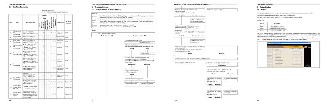
- Specifications, page 55: CHAPTER 1 CONTROLLER
- Troubleshooting, page 87: Troubleshooting
- Diagram, page 203: (8) (Already disconnected E-01, E-02 and E-06)
- Color page, page 33: CHAPTER 1 CONTROLLER
Other manuals for this machine
Save 10% on 2 manuals, 15% on 3 or more. Other manuals for the EP13PNT, EP15PNT, EP16CPNT, EP18CPNT, EP16PNT, EP18PNT, EP20PNT, EP16CPN, EP18CPN, EP16PN, EP18PN, EP20PN are listed below. Editions cover different serial number ranges: check the serial coverage and tick only the ones that match your machine.
Added to your cart. View cart
This is a service manual
Here's how it compares to the other manual types.
Service manual
Factory repair procedures and technical information such as specifications, troubleshooting, and wiring and hydraulic diagrams, for the models and systems the manual covers. See What's inside for its topics.
Operator's manual
Safe operation, controls, maintenance schedules, lubrication points, inspections, and basic checks. Repair procedures are in the service manual.
Parts manual
Illustrated diagrams with factory part numbers for identifying components and ordering parts. Repair procedures are in the service manual.
Engine service manuals are sometimes sold separately, since certain machine models were offered with more than one engine option.
What it's used for
Factory manual for in-house farm and construction shop use. Straightforward, complete, and easy to follow. It contains the OEM information dealership service departments and parts counters use to diagnose problems, identify components, and perform maintenance or repairs correctly.
Service shops and owner/operators who repair their own equipment
Identifying correct parts and seeing how assemblies come apart and go back together
Keeping equipment running with less downtime
Factory manual, 319 pages
Quantity one is the manual described above.
Fast free USA shipping
Ships in 1 business day.
60-day returns
Free if the mistake is ours. A manual ordered in error must come back unopened in its shrink-wrap; you pay return shipping and a 20% restocking fee applies. Return policy
Binder not included
Manuals over about 300 pages may need a standard 3-ring binder, which you can buy locally to keep the pages organized for shop use.
Other editions and similar models
Questions about model, serial number, engine coverage or contents? Contact us before purchasing and we'll help confirm it's the right manual. Please verify the manual type, machine model, serial number range and engine coverage before purchasing: manuals ordered in error carry a 20% restocking fee (return policy).