Clark TMG 12, 25 Forklift Service Manual
412 pages · Publication SM-616
Added to your cart. View cart
- Models
- TMG 12, 25
- Manual type
- Service Manual
- Pages
- 412
- Publication
- SM-616
- Condition
- Brand new
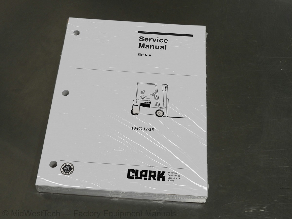
What's inside
From the manual's own table of contents: 31 sections, 299 entries. See sample pages (PDF, 333 KB)
CONTENTS, COVER, & FOREWORD4 topics
- CONTENTS, by Group & Section
- CONTENTS, Alphabeticallt
- Using this Manual
- Cover of Manual
SAFE MAINTENANCE10 topics
- Safety
- Safe Maintenance Practices
- Safety Signs and Messages
- Lifting, Jacking, and Blocking
- Raising Drive Wheels
- Chaining the Upright in Raised Position
- Raising Rear of Truck
- Raising Entire Truck
- Shipping Tie-Down Instructions
- Towing
PERIODIC SERVICE16 topics
- Maintenance Schedule
- Periodic Service” and “Planned Maintenance
- Determining Maintenance Intervals
- Service Chart/Lubrication Points
- Recommended Periodic Service Schedule
- Planned Maintenance Program
- Introduction to Planned Maintenance
- External Inspection
- Operational Checks
- Internal Inspection
- Air Cleaning the Truck
- Minor Adjustments Covered by PM
- Lubrication
- Critical Fastener Torque Checks
- Wrapping Up the PM
- PM Inspection Form
BATTERY15 topics
- Battery Handling
- Battery Removal
- Battery Maintenance
- Maximum Battery Life
- Battery Vents
- Battery Cleaning
- Battery Charging
- Battery Electrolyte
- CleanBattery Compartment
- Replacement Batteries
- Battery Installation
- Keeping Battery Records
- Battery Tests
- Specific Gravity Test
- Load Test
WIRING, SWITCHES, & INSTRUMENTS25 topics
- Schematic Circuit Diagrams
- Standard Truck
- Standard + Commad
- Standard. + Pump Control
- Command + Pump Control
- Accessories
- Options
- Service Tips for Electrical Components
- Safe Preparations
- Checking Power Cables
- Torquing Fasteners
- Connecting and Mounting Components
- Wiring and Cables Installation
- Cables (Standard Truck)
- Main Harness
- Main Accessory Harnes
- Switches and Sensors
- Accelerator Control Switch
- Brake Switches
- Direction Control Switches
- Lift and Tilt Pump Switches
- Steer Angle Sensor
- Instrument Panel
- Dash Display
- Command System Display (Option)
MOTORS36 topics
- Specifications & Description
- Specifications
- Descriptions and Locations
- Inspection and Troubleshooting
- Inspection Procedures
- Brush & Commutator Maintenance
- Brush & Commutator Inspection
- Brush Inspection Chart
- Drive Motor Overhaul
- Drive Motor Removal and Installation
- Drive Motor Exploded View
- Drive Motor Disassembly
- Drive Motor Components Inspection
- Drive Motor Assembly
- Lift Pump Motor Overhaul
- Lift Pump Motor Exploded View
- Removal
- Installation
- Disassembly
- Inspection
- Reconditioning
- Assembly
- Steer Pump Motor Overhaul
- Steer Pump Motor Removal and Installation
- Troubleshooting Prior to Disassembly
- Steer Pump Motor Exploded View
- Brush Removal and Inspection
- Motor Disassembly
- Armature Removal
- Motor Inspection
- Armature and Bearing Repair
- Bearing Lubrication
- Motor Assembly
- Drive Motors
- Lift Pump Motor
- Steering Pump Motor
CONTACTORS2 topics
- Specifications
- Overhaul
MOTOR CONTROLS29 topics
- Specifications and Description
- Specifications
- Description
- Sequence of Operations
- Sequence #1: Normal Off State
- Sequence #2: Connecting the Battery
- Sequence #3a: Closing the Key Switch
- Sequence #3b: Closing The Key Switch
- Sequence #4: Park Brake & Static Return to Off (SRO) Checks
- Sequence #5: Selecting a Direction & Energizing the PS Contactor
- Sequence #6: Turning on the Traction Controls
- Sequence #7: Brake Pedal Regen
- Sequence #8a: Regenerative Braking (Plugging)
- Sequence #8b: Regenerative Braking (Plugging)
- Sequence #9: Steer Potentiometer Operation
- Handset Operation
- Purpose of Handset
- Connection and Start-Up
- Function Setting Procedures
- Status Code Scrolling Procedure
- TMG248 Traction Controller Function Settings
- TMG248 Pump Controller Function Settings
- Function Descriptions
- Diagnostic Status Codes
- Introduction
- Initial Troubleshooting
- Tools and Test Equipment
- Status Code Charts
- Controllers Removal and Replacement
DRIVE AXLE22 topics
- Drive Axle Specifications and Description
- Specifications
- Description
- Troubleshooting
- Fluid Check and Change
- Fluid Level Check
- Fluid Change
- Removal and Installation
- Drive Axle Overhaul
- Introduction
- Drive Unit Disassembly
- Ring Gear Shaft Disassembly
- Input Pinion Gear Carrier Disassembly
- Drive Axle Shaft Disassembly
- Ring Gear Shaft Inboard Bearing Removal
- Cleaning and Inspection
- Drive Unit Reassembly
- Drive Axle Shaft Reassembly
- Input Pinion Gear Carrier Reassembly
- Ring Gear Shaft Reassembly
- Drive Axle Reassembly
- Spiral Bevel and Hypoid Tooth Bearing Contact Chart
WHEELS AND TIRES4 topics
- Mounting and Maintenance
- Removal and Installation
- Cushion Tire Replacement
- Pneumatic Tire Maintenance
BRAKES6 topics
- Fluid Check & Fill
- Bleeding
- Pedal & Master Cylinder
- Brake Caliper Removal
- Parking Brake
- Brake Overhaul
STEERING29 topics
- Steering Column
- Steering Column and Component Removal
- Key Switch Removal
- Hand Wheel, Horn Contact Ring, and Directional Control Assembly Removal
- Detent Spring Removal
- Column Tilt Lock Assembly Removal
- Steering Gear and Lower Steering Column Removal
- Steer Column and Component Replacement
- Steering Gear and Lower Steering Column Replacement
- Column Tilt Lock Assembly Replacement
- Directional Control Assembly Reassembly
- Directional Control Assembly and Key
- Switch Replacement
- Steering Hand Wheel Replacement
- Steering Relief Pressure
- Steering Gear Overhaul
- Disassembly
- Parts Inspection
- Reassembly
- Steer Axle
- Trunnion Bearings Maintenance
- Wheel Bearing Maintenance
- Steer Angle Sensor Removal and Replacement
- Steer Cylinder Removal and Replacement
- Trunnion Removal and Replacement
- Steer Axle Linkage Removal and Replacement
- Trunnion Bearings Removal and Replacement
- Steer Cylinder Overhaul
- Steer Pump Overhaul
HYDRAULIC SYSTEM44 topics
- Specifications
- Serviceable Items
- Service Intervals
- Description
- Fluids and Filters
- Fluid Level Check
- Filter Change
- Breather Maintenance
- Fluid Change
- Noisy Pump
- Pump Not Delivering Hydraulic Fluid
- Failure to Build Pressure
- Pump Not Developing Sufficient Pressure
- Pump Output Low
- Overheated Pump and/or Fluid
- External Leakage
- Shaft Seal Leakage
- No lift, tilt, or auxiliary function
- No motion, slow or jerky action of hydraulic system
- Foaming hydraulic fluid
- Overheated hydraulic fluid
- Load cannot be lifted to maximum height
- Oil leaks at top of lift (secondary) cylinder(s)
- Oil leak at tilt or auxiliary function cylinder
- Load will not hold
- Oil leaks at either end of main hydraulic valve spool
- Spring-centered spools do not return to neutral
- No relief valve action (high pressure)
- Load drops when spool is moved from neutral to lift position
- Pressure Checks and Adjustments
- Relief Pressure Checks
- Main Pressure Relief Adjustment
- Auxiliary Pressure Relief Adjustment
- Flow Control Adjustments
- Removal and Installation
- Pump Overhaul
- Removal and Installation
- Routine Maintenance
- Overhaul Procedures
- Running-In
- Control Valve Overhaul
- Valve Removal
- Valve Installation
- Valve Overhaul Procedures
Show all 31 sections
TILT CYLINDERS8 topics
- Checks & Adjustments
- Tilt Cylinder Drift Check
- Drift Causes and Remedies
- Tilt Cylinder Racking Check
- Forward Adjustment
- Backward Adjustment
- Tilt Flow Control Adjustments
- Removal & Replacement
UPRIGHTS7 topics
- Removal & Installation
- Lift Chain Inspection & Service Guidelines
- Periodic Inspections
- Chain Length Adjustments
- Chain Lubrication
- Lift Chain Service Tips
- Manufacturer’s Service Literature
COUNTERWEIGHT AND CHASSIS3 topics
- Counterweight Removal & Installation
- Overhead Guard Removal & Installation
- Floor Plate, Seat, & Seat Deck
SPECIFICATIONS8 topics
- Nameplate & Decals
- Locations
- Descriptions
- General Specifications
- Weights and Performance Specifications
- Critical Fastener Torque Specifications
- Group Specifications
- Hydraulic Fitting Tightening Procedure
Inside this manual
Real pages from this service manual (412 pages). Open the sample pages (PDF, 332 KB)
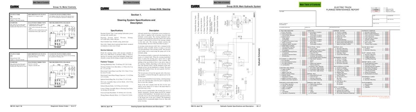
- Troubleshooting, page 211: Group 19, Motor Controls
- Specifications, page 283: Steering System Specifications and Description • 25-1-1
- Diagram, page 331: Hydraulic System Specifications and Description • 29-1-7
- Color page, page 36: 34UPRIGHT-CARRIAGE
This is a service manual
Here's how it compares to the other manual types.
Service manual
Factory repair procedures and technical information such as specifications, troubleshooting, and wiring and hydraulic diagrams, for the models and systems the manual covers. See What's inside for its topics.
Operator's manual
Safe operation, controls, maintenance schedules, lubrication points, inspections, and basic checks. Repair procedures are in the service manual.
Parts manual
Illustrated diagrams with factory part numbers for identifying components and ordering parts. Repair procedures are in the service manual.
Engine service manuals are sometimes sold separately, since certain machine models were offered with more than one engine option.
What it's used for
Factory manual for in-house farm and construction shop use. Straightforward, complete, and easy to follow. It contains the OEM information dealership service departments and parts counters use to diagnose problems, identify components, and perform maintenance or repairs correctly.
Service shops and owner/operators who repair their own equipment
Identifying correct parts and seeing how assemblies come apart and go back together
Keeping equipment running with less downtime
Factory manual, 412 pages
Quantity one is the manual described above.
Fast free USA shipping
Ships in 1 business day.
60-day returns
Free if the mistake is ours. A manual ordered in error must come back unopened in its shrink-wrap; you pay return shipping and a 20% restocking fee applies. Return policy
Binder not included
Manuals over about 300 pages may need a standard 3-ring binder, which you can buy locally to keep the pages organized for shop use.
Questions about model, serial number, engine coverage or contents? Contact us before purchasing and we'll help confirm it's the right manual. Please verify the manual type, machine model, serial number range and engine coverage before purchasing: manuals ordered in error carry a 20% restocking fee (return policy).