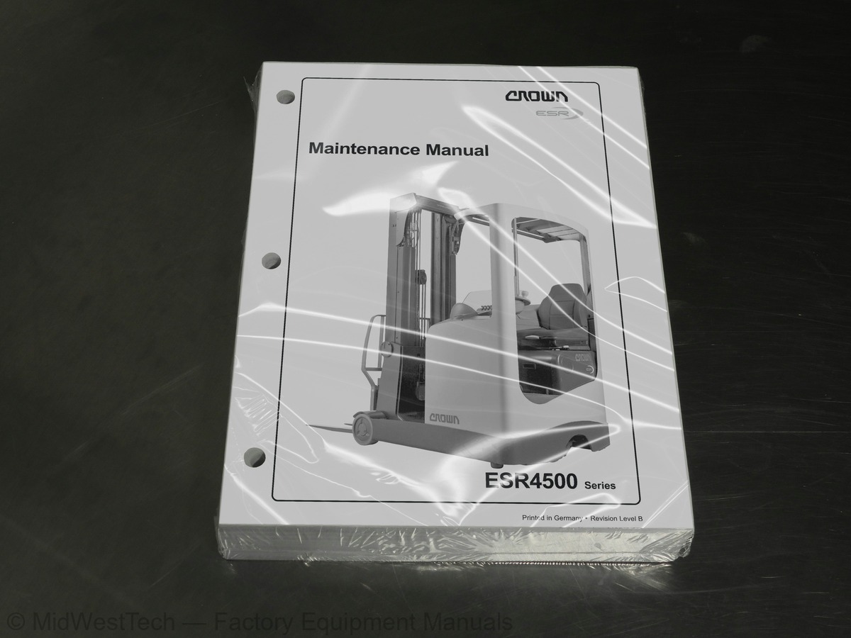
Crown ESR4500 Forklift Service Manual
478 pages · Publication 812549-006_Rev-B
Added to your cart. View cart
- Models
- ESR4500
- Manual type
- Service Manual
- Pages
- 478
- Publication
- 812549-006_Rev-B
- Condition
- Brand new
What's inside
From the manual's own table of contents: 153 sections, 640 entries. See sample pages (PDF, 725 KB)
Maintenance and Repair3 topics
- Before Leaving the Truck
- Before Carrying out Work on the Truck
- Before Operating the Truck
General4 topics
- Operating Instructions
- Service Training
- Ordering Spare Parts
- Using the Manual
Component Access3 topics
- Access to the Motor Compartment
- Removing the Floorboard
- Plastic Panel Disassembly / Assembly
Maintenance6 topics
- Recommended Lubricants and Oils
- Lubricants
- Cold Store Trucks
- Truck Decommissioning
- Restoring the Truck to Service
- Battery Maintenance
Abbreviations8 topics
- Lifting
- Lowering
- Mast Reach Carriage Retraction
- Mast Reach Carriage Extension
- Tilt Back Circuit
- Tilt Down Circuit
- Sideshift Left
- Sideshift Right
Hydraulic Components5 topics
- Hydraulic Lines
- Valve Block
- Relief Valve RV1
- Lowering Speed Adjustment Valve AVL
- Pressure Load Switch PLS
Filter3 topics
- Replacing the Return Filter
- Replacing the Aeration Filter
- Replacing the Suction Filter
Show all 153 sections
Hydraulic Pump2 topics
- Disassembly
- Commissioning
Servicing1 topic
- General
Gear Unit Disassembly / Assembly7 topics
- Assembly
- Preparing the gear unit
- Inserting the bevel pinion shaft
- Assembling the flange shaft
- Adjusting the Bevel Wheel Set
- Checking the flank tooth bearing
- Final Assembly
Electrical Components8 topics
- BRAKE
- FAN3, FAN4
- HGTS from serial no. 5A203820
- PVAR
- PVAL
- PVRT
- PVRE
- SFS 1SA
Status Codes6 topics
- When a Service Code Occurs
- Fault during power-up
- The fault is not electrical
- inputs
- Power Up Circuit up to Ser. No. 5A204796
- Power Up Circuit up from Ser. No. 5A204798
Statuscode 20022 topics
- Statuscode 260
- Statuscode 261
- Statuscode 262
- Statuscode 263
- Statuscode 264
- Statuscode 265
- Statuscode 266
- Statuscode 267
- Statuscode 268
- Statuscode 340
- Statuscode 341
- Statuscode 880
- Statuscode 881
- Statuscode 883
- Statuscode 884
- Statuscode 885
- Statuscode 886
- APPENDIX
- Display not active
- ON/OFF
- message display active
- Main contactor briefly activated after power up
Display13 topics
- Design and Functions
- Steer Angle Display
- Travel Direction Display
- Battery Charge Status Display
- Operator error display
- Service Display
- Function Keys
- Message Display
- Capacity Data Monitor
- Brake Fluid Level Indicator
- Steer Fault Display
- Parking Brake Display
- Performance Setting Display
Operator Menu3 topics
- Tilt Position - Assist On / Off
- Rack Height Select On / Off
- Programming Rack Height Select
Chapter structure74 topics
- ANALYZER
- A1 STATUS
- A2 INPUTS
- A3 OUTPUTS
- CALIBRATION
- C1 Accelerator Pedal
- C2 Raise Lower Handle
- C3 Reach Handle
- C4 Tilt Handle
- C5 Sideshift Handle
- C6 5th Function Handle
- C7 Height
- C8 Weight
- C9 Fork Positioning
- C10 Reach retract slow down
- C11 Save?
- FEATURE
- F1 Truck size
- F2 FLS Switch
- F3 Height Encoder
- F4 Lower Cut out
- F5 Fifth Function
- F6 Max Load
- F7 Capacity Data Monitor CDM
- F8 Alarm 2
- F9 Beacon
- F10 User Performance
- F11 User Codes
- F12 Language
- F13 Truck lockout
- F14 Rack select
- F15 Height & weight on/off
- F16 Timer on/off
- F17 Error log on/off
- F18 Operator Alarm1 on/off
- F19 Battery low level alarm
- F20 Fork positioning
- F21 Change value Euro/US
- F22 Save
- HOUR METER
- H1 Run
- H2 TDM Traction Drive Module
- H3 HDM Pump Drive Module
- H4 VCM Vehicle Controll Module
- H5 SDM Steer Drive Module
- H6 Display
- H7 Set Service Timer
- H8 Escape
- LOG EVENTS
- L1 History
- L2 Totals
- L3 Erase
- L4 Escape
- PERFORMANCE
- P1 Setup P1
- P2 Setup P2
- P3 Setup P3
- P4 BDI setting
- P5 Travel > LCS
- P6 Travel > FLS
- P7 Travel > Custom
- P8 Lower > Custom
- P9 Reach > Custom
- P10 5th Function left
- P11 5th Function right
- P12 Steer low speed
- P13 Steer high speed
- P14 Brake at ramp
- P15 Save
- UTILITIES
- U1 Software Version
- U2 Hour Set
- U3 Accy Override
- U4 Escape
Service Menu19 topics
- Access to Service Level
- Overview of menu items
- Analyzer
- Calibration
- Feature
- Hour Meter
- Log Events
- Performance
- Utilities
- A1.12 Status
- A2.6 Inputs
- A2.13 Inputs
- A2.20 Inputs
- A2.25 Inputs
- A2.32 Inputs
- A2.37 Inputs
- A3.9 Outputs
- A3.16 Outputs
- A3.18 Outputs
Calibration6 topics
- C1 - C3 Calibration
- C4 - C5 Calibration
- C6 - C7.1 Calibration
- C7.5 Calibration
- C8 Calibration
- C9 Calibration
Feature8 topics
- F1 - F3 Feature
- F4 - F6 Feature
- F7 Feature
- F8 Feature
- F9 - F10 Feature
- F11 Feature
- H1 - H3 Hourmeter
- H4 - H8 Hourmeter
Performance6 topics
- P1 - P1.5.1 Performance
- P1.10.1 Performance
- P1.15 Performance
- P2 - P6 Performance
- P7 - P10 Performance
- P11 - P15.2 Performance
Utilities2 topics
- U1 - U2 Utilities
- U3 - U4 Utilities
Service Level (Software Version 814759-014 )2 topics
- Rack Height Select On / Off
- Programming Rack Height Select
Service Level (Software Version 814759-014)76 topics
- Chapter structure
- ANALYZER
- A1 STATUS
- A2 INPUTS
- A3 OUTPUTS
- CALIBRATION
- C1 Accelerator Pedal
- C2 Raise Lower Handle
- C3 Reach Handle
- C4 Tilt Handle
- C5 Sideshift Handle
- C6 5th Function Handle
- C7 Height
- C8 Weight
- C9 Fork Positioning
- C10 Reach retract slow down
- C11 Save?
- FEATURE
- F1 Truck size
- F2 FLS Switch
- F3 Height Encoder
- F4 Lower Cut out
- F5 Fifth Function
- F6 Max Load
- F7 Capacity Data Monitor CDM
- F8 Alarm 2
- F9 Beacon
- F10 User Performance
- F11 User Codes
- F12 Language
- F13 Change value Euro/US
- F14 Rack select
- F15 Height & weight on/off
- F16 Timer on/off
- F17 Error log on/off
- F18 Operator Alarm1 on/off
- F19 Battery low level alarm
- F20 Fork positioning
- F21 Truck lockout
- F22 Save
- HOUR METER
- H1 Run
- H2 SDM Steer Drive Module
- Low / Middle / Full
- H3 TDM Traction Drive Module
- H4 HDM Pump Drive Module
- H5 VCM Vehicle Controll Module
- H6 Display
- H7 Set Service Timer
- H8 Escape
- LOG EVENTS
- L1 History
- L2 Totals
- L3 Erase
- L4 Escape
- PERFORMANCE
- P1 Setup P1
- P2 Setup P2
- P3 Setup P3
- P4 BDI setting
- P5 Travel > LCS
- P6 Travel > FLS
- P7 Travel > Custom
- P8 Lower > Custom
- P9 Reach > Custom
- P10 5th Function left
- P11 5th Function right
- P12 Steer low speed
- P13 Steer high speed
- P14 Brake at ramp
- P15 Save
- UTILITIES
- U1 Software Version
- U2 Hour Set
- U3 Accy Override
- U4 Escape
Access to Service Level3 topics
- Overview of menu items
- Hour Meter
- Log Events
Analyzer22 topics
- A1.12 Status
- A2.6 Inputs
- A2.13 Inputs
- A2.20 Inputs
- A2.25 Inputs
- A2.32 Inputs
- F4 - F6 Feature
- F7 Feature
- F8 Feature
- F9 - F10 Feature
- F11 Feature
- H1 - H3 Hourmeter
- H4 - H8 Hourmeter
- L4 Log Events
- P1 - P1.5.1 Performance
- P1.10.1 Performance
- P1.15 Performance
- P2 - P6 Performance
- P7 - P10 Performance
- P11 - P15 Performance
- U1 - U2 Utilities
- U3 - U4 Utilities
Service Level (Software Version 814759-031)13 topics
- Design and Functions
- Steer Angle Display
- Travel Direction Display
- Battery Charge Status Display
- Operator error display
- Service Display
- Function Keys
- Message Display
- Capacity Data Monitor
- Brake Fluid Level Indicator
- Display 360° steering status
- Parking Brake Display
- Performance Setting Display
Operator Menu (Software Version 814759-031)84 topics
- Tilt Position - Assist On / Off
- Rack Height Select On / Off
- Programming Rack Height Select
- ANALYZER
- A1 STATUS
- A2 INPUTS
- A3 OUTPUTS
- A4 ESCAPE
- CALIBRATION
- C1 Accelerator Pedal
- C2 Raise Lower Handle
- C3 Reach Handle
- C4 Tilt Handle
- C5 Sideshift Handle
- C6 5th Function Handle
- C7 Height
- F8Alarm 2
- F13 Change value Euro/US Unit
- F15 Height & weight
- F17 Error log No/Yes
- F18 Operator Alarm1 on/off
- F19 Battery Low Level Alarm
- F20 Fork positioning
- F21 Choose Steering
- F22 Truck Lockout No/Yes
- F23 Save
- H1 Run
- (H2 Not available)
- H3 TDM Traction Drive Module
- H4 HDM Hydraulic Drive Module
- H5 Key On Time
- (H6 Not available)
- H7 Set Service Timer
- H8 Escape
- L1 History
- L2 Totals
- P12 Steer Sensitivity
- (P13 Not available)
- P15 Set default
- P16 Save
- UTILITIES
- U1 Software Version
- U2 Hour Set
- U3 Brake Override
- U4 Check Fan 1 - 4 ON/OFF
- U5 Escape
- Overview of menu items
- Analyzer
- Calibration
- Feature
- Hour Meter
- Log Events
- Performance
- Utilities
- A1.12 Status
- A2.6 Inputs
- A2.13 Inputs
- A2.20 Inputs
- A2.25 Inputs
- A2.32 Inputs
- A2.37 Inputs
- A3.9 Outputs
- A3.16 Outputs
- A3.18 Outputs
- C1 - C3 Calibration
- C4 - C5 Calibration
- C6 - C7.1 Calibration
- Calibration
- C7.5 Calibration
- C8 Calibration
- C9 Calibration
- F1 - F3 Feature
- F4 - F6 Feature
- F7 Feature
- F8 Feature
- F9 - F10 Feature
- F11 Feature
- H1 - H3 Hourmeter
- H4 - H8 Hourmeter
- L1 - L3.2 Log Events
- L4 Log Events
- P1 - P1.5.1 Performance
- P1.10.1 Performance
- U3 - U5 Utilities
Wheel Brake Cylinder1 topic
- brake fluid
Disassembly1 topic
- Test and Inspection
Setting the brake pedal clearance2 topics
- Functional Description
- Quadrant - Definition
Error routine2 topics
- When the error routine starts
- Ending the error routine
Examples of steer faults1 topic
- turned 160° to the right
Steering Sensor (ECR4)15 topics
- Feature Description
- Causes of error routine activation
- Other error causes
- Examples of steer faults
- Setting the proximity switches SFS
- Steer Motor and Gear Unit
- Removal
- Separating Gear Unit and Motor
- Assembling Gear Unit and Motor
- Assembly
- Steering Wheel
- Removal
- Steering Sensor (ECR4)
- Removal
- Assembly
Mast7 topics
- Torque Requirements
- Lifting Gear Minimum Capacity
- Mast Testing (Assembled)
- Flaking
- Mast Shock Absorbers
- Mast end stops
- Fork Adjustment
Dismantling and Assembling the Mast4 topics
- Dismantling
- Fork Carriage Removal
- 2nd Mast Stage Removal
- 1st Mast Stage Removal
Replacing the Mast Rollers9 topics
- Mast Roller Assembly
- Calculating the Roller Diameter
- Calculating the Required Number of Shims
- Outer Mast / 1st Mast Stage
- 1st Mast Stage / 2nd Mast Stage
- Fork Carriage
- Final Work and Settings
- Torque Requirements
- Lifting Gear Minimum Capacity
Lift cylinder removal / assembly1 topic
- Lifting Gear Minimum Capacity
Inspection11 topics
- Cleaning
- Wear
- Freedom of Movement of Chain Links
- Chain Tension
- Chain Anchor and Pulleys
- Worn Connection Plates
- Protruding or Turned Chain Pins
- Corrosion
- Chain Lateral Wear
- Uneven Chain Tension
- Misalignment of Lift Components
Fork Tines2 topics
- Terms
- Fork Identification
Checking the Fork3 topics
- Crack Inspection
- Verticality Test
- Fork Blade Warping
Reach2 topics
- Side Roller Adjustment
- Backing Roller Adjustment
Cylinders2 topics
- Safety when working on hydraulic systems
- Components
Dismantling4 topics
- Rod Seal Removal
- Piston Rod Removal
- Piston Rod Assembly
- Installing the Rod Seal
Free-Lift Cylinder11 topics
- Removal and Assembly
- Rod Seal Removal
- Piston Rod Removal
- Cushion Removal
- Cushion Installation
- Piston Rod Assembly
- Installing the Rod Seal
- Rod Seal Removal
- Piston Rod Removal
- Piston Rod Assembly
- Installing the Rod Seal
Inside this manual
Real pages from this service manual (478 pages). Open the sample pages (PDF, 724 KB)

- Troubleshooting, page 141: Status Code 280
- Specifications, page 372: Using a crowbar push the 1st mast stage in the
- Diagram, page 421: MS-DIA-2140
- Foldout diagram (color), page 436: ESR4500 06/2004 • Printed in Germany
This is a service manual
Here's how it compares to the other manual types.
Service manual
Factory repair procedures and technical information such as specifications, troubleshooting, and wiring and hydraulic diagrams, for the models and systems the manual covers. See What's inside for its topics.
Operator's manual
Safe operation, controls, maintenance schedules, lubrication points, inspections, and basic checks. Repair procedures are in the service manual.
Parts manual
Illustrated diagrams with factory part numbers for identifying components and ordering parts. Repair procedures are in the service manual.
Engine service manuals are sometimes sold separately, since certain machine models were offered with more than one engine option.
What it's used for
Factory manual for in-house farm and construction shop use. Straightforward, complete, and easy to follow. It contains the OEM information dealership service departments and parts counters use to diagnose problems, identify components, and perform maintenance or repairs correctly.
Service shops and owner/operators who repair their own equipment
Identifying correct parts and seeing how assemblies come apart and go back together
Keeping equipment running with less downtime
Factory manual, 478 pages
Quantity one is the manual described above.
Fast free USA shipping
Ships in 1 business day.
60-day returns
Free if the mistake is ours. A manual ordered in error must come back unopened in its shrink-wrap; you pay return shipping and a 20% restocking fee applies. Return policy
Binder not included
Manuals over about 300 pages may need a standard 3-ring binder, which you can buy locally to keep the pages organized for shop use.
Other editions and similar models
Questions about model, serial number, engine coverage or contents? Contact us before purchasing and we'll help confirm it's the right manual. Please verify the manual type, machine model, serial number range and engine coverage before purchasing: manuals ordered in error carry a 20% restocking fee (return policy).