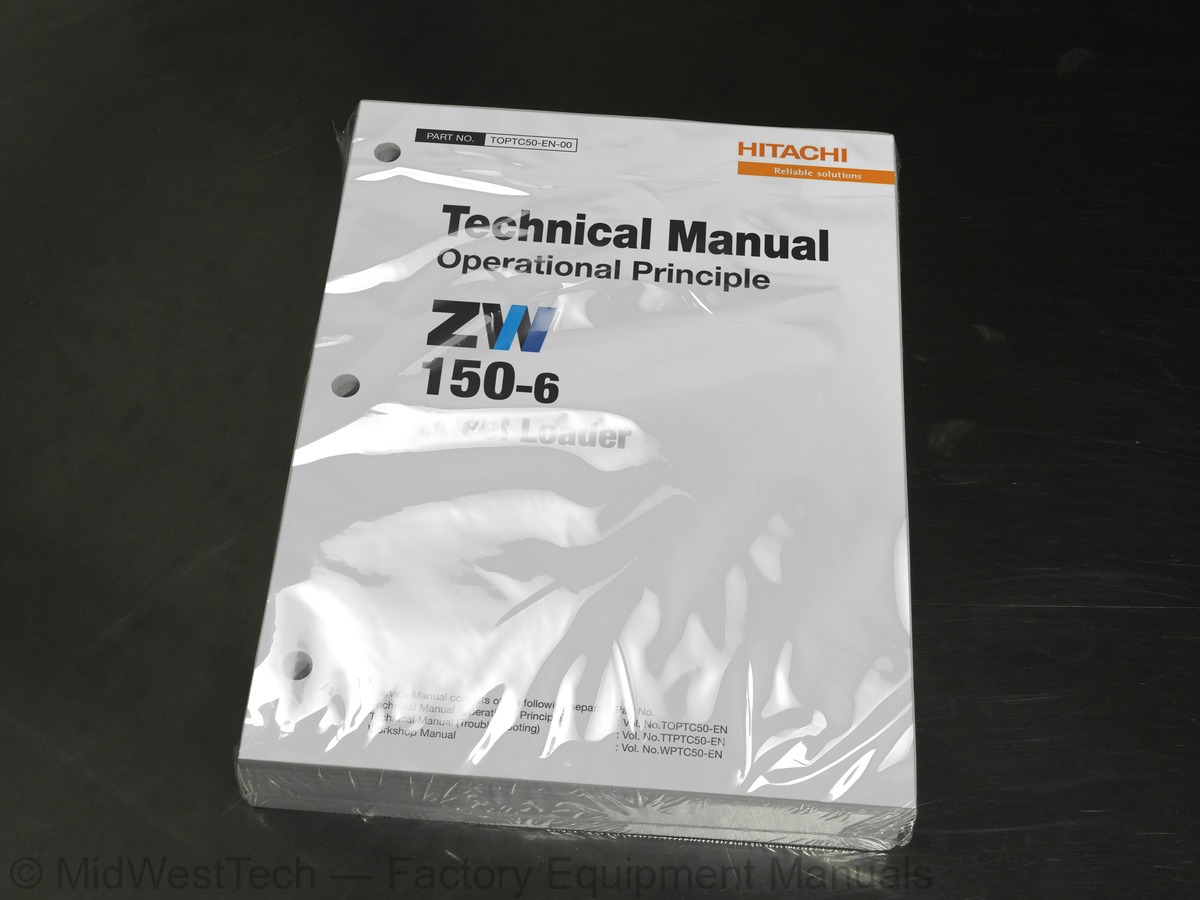
Hitachi ZW150-6 Wheel Loader Operational Principle Technical Service Manual
503 pages · Publication TOPTC50-EN-00
Added to your cart. View cart
- Models
- ZW150-6
- Manual type
- Operational Principle Technical Service Manual
- Pages
- 503
- Publication
- TOPTC50-EN-00
- Condition
- Brand new
What's inside
From the manual's own table of contents: 112 topics. See sample pages (PDF, 568 KB)
- Specifications
- Main Component (Overview)
- Main Component
- Electrical System (Overview)
- Air Cleaner and Radiator Assembly
- Battery Box
- Hydraulic Oil Tank
- Fuel Tank
- Engine
- Aftertreatment Device
- Transmission, HST Motor
- Fan Valve
- HST Pump, 3-Dear Pump Unit
- Control Valve
- Manifold Valve
- Brake Charge Valve
- Emergency Steering Block
- Emergency Steering Pump
- Ride Control Valve
- DEF Tank
- DEF Supply Module
- Engine Accessories
- Hydraulic Component
- Electrical Component
Show all 112 topics
- Outline
- CAN Circuit
- Summary
- Engine Control (ECM)
- HST Pump/Motor Control, Transmission Control
- Fan Control, Valve Control
- Other Controls
- Circuit
- ECM System
- Fuel Injection Control
- Fuel Injection Amount Correction Control
- EGR Control
- Preheating Control
- Variable Turbocharger Control
- Alarm Control
- Urea SCR System
- (INDUCEMENT)
- Aftertreatment Device Regeneration Control
- Main Circuit
- HST Circuit
- Pilot Circuit/Fan Circuit
- Fan Circuit
- Transmission Circuit
- Electric Power Circuit (Key Switch: OFF)
- Accessory Circuit (Key Switch: ACC)
- Starting Circuit (Key Switch: START)
- Charging Circuit (Key Switch: ON)
- Surge Voltage Prevention Circuit
- Pilot Shut-Off Circuit (Key Switch: ON)
- Auto Shut-Down Circuit (Option)
- Engine Stop Circuit
- Steering Column Box Circuit
- Headlight Circuit
- Hazard Light Circuit (Key Switch: OFF)
- Turn Signal Light Circuit
- Horn Circuit (Key Switch: OFF)
- Reverse Light, Back Buzzer Circuit
- Brake Light Circuit
- Parking Brake Circuit
- Accessory Circuit
- Work Light Circuit
- Wiper Circuit
- Cab Light Circuit
- Rotary Group
- Displacement Angle Control Cylinder
- Solenoid Valve
- Forward/Reverse Control Solenoid Valve
- Cutoff Valve
- High-Pressure Relief Valve
- Low-Pressure Relief Valve
- HST Charging Pump
- 3-Gear Pump Unit
- Hydraulic Circuit
- Main Relief Valve
- Overload Relief Valve (With Make-Up Function)
- For Lift Arm Raise and Bucket Tilt Circuits
- Make-Up Valve
- Flow Rate Control Valve
- FAN MOTOR
- Fan Valve (With Fan Reverse Rotation) (Optional)
- Structure
- Operation
- Overload Relief Valve
- Makeup Valve
- Regulator
- Motor Displacement Angle Control
- Flushing Valve
- Front Attachment)
- Electromagnetic Detent
- Outline (Auxiliary Pilot Valve) (Optional)
- Pilot Reducing Valve
- Parking Brake Solenoid Valve
- Control Lever Lock Solenoid Valve
- Pilot Accumulator
- Clutch Pressure Control Solenoid Valve
- Parking Brake
- Differential
- Torque Proportioning Differential (TPD)
- Limited Slip Differential (LSD) (Optional)
- Service Brake
- Final Drive / Axle Shaft
- Charge-Cut Spool
- Drain Plug
- Propeller Shaft
- HST Cooler Bypass Check Valve
- Service Brake Accumulator
- Ride Control Accumulator
- Emergency Steering Check Block
Inside this manual
Real pages from this operational principle technical service manual (486 pages). Open the sample pages (PDF, 567 KB)
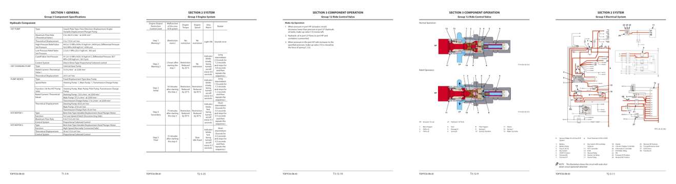
- Specifications, page 50: SECTION 1 GENERAL
- Repair procedure, page 183: Group 3 Engine System
- Diagram, page 470: Group 12 Ride Control Valve
- Color page, page 469: SECTION 3 COMPONENT OPERATION
- Color page, page 261: Group 5 Electrical System
Other manuals for this machine
Save 10% on 2 manuals, 15% on 3 or more. Other manuals for the ZW150-6 are listed below. Editions cover different serial number ranges: check the serial coverage and tick only the ones that match your machine.
Added to your cart. View cart
Manual types
This manual is a operational principle technical service manual. For reference, the three main manual types:
Service manual
Factory repair procedures and technical information such as specifications, troubleshooting, and wiring and hydraulic diagrams, for the models and systems the manual covers. See What's inside for its topics.
Operator's manual
Safe operation, controls, maintenance schedules, lubrication points, inspections, and basic checks. Repair procedures are in the service manual.
Parts manual
Illustrated diagrams with factory part numbers for identifying components and ordering parts. Repair procedures are in the service manual.
Engine service manuals are sometimes sold separately, since certain machine models were offered with more than one engine option.
What it's used for
Factory manual for in-house farm and construction shop use. Straightforward, complete, and easy to follow. It contains the OEM information dealership service departments and parts counters use to diagnose problems, identify components, and perform maintenance or repairs correctly.
Service shops and owner/operators who repair their own equipment
Identifying correct parts and seeing how assemblies come apart and go back together
Keeping equipment running with less downtime
Factory manual, 503 pages
Quantity one is the manual described above.
Fast free USA shipping
Ships in 1 business day.
60-day returns
Free if the mistake is ours. A manual ordered in error must come back unopened in its shrink-wrap; you pay return shipping and a 20% restocking fee applies. Return policy
Binder not included
Manuals over about 300 pages may need a standard 3-ring binder, which you can buy locally to keep the pages organized for shop use.
Other editions and similar models
Questions about model, serial number, engine coverage or contents? Contact us before purchasing and we'll help confirm it's the right manual. Please verify the manual type, machine model, serial number range and engine coverage before purchasing: manuals ordered in error carry a 20% restocking fee (return policy).