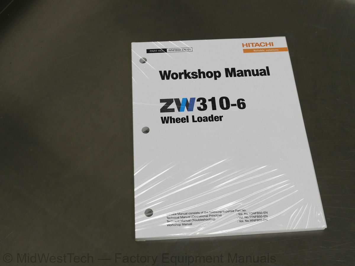
Hitachi ZW310-6 Wheel Loader Workshop Service Manual
133 pages · Publication WNFB50-EN-01
Added to your cart. View cart
- Models
- ZW310-6
- Manual type
- Workshop Service Manual
- Pages
- 133
- Publication
- WNFB50-EN-01
- Condition
- Brand new
What's inside
From the manual's own table of contents: 142 topics. See sample pages (PDF, 508 KB)
- Assembling
- Tightening Bolts and Nuts
- Piping Joint
- Painting
- Bleeding Air from Hydraulic Oil Tank
- Bleeding Air from Hydraulic System
- Bleed Air from the Fuel System
- Bleeding Air from Radiator
- Bleeding Air from Brake (Axle)
- Release Procedure
- Maintenance
- Center Hinge
- Pilot Valve (Two Lever Type )
- Pin and Bushing
- Standard Dimensions for Lift Arm and Bucket
- Bucket Stopper Clearance
- Removal and Installation of Cab
- Removal and Installation of Counterweight
- Removal and Installation of Center Hinge
- Hydraulic Hoses of Front Chassis Side
- Removal and Installation of Engine
- Removal and Installation of Exterior Parts
- Removal and Installation of Air Cleaner
- Intercooler, and Torque Converter Cooler
Show all 142 topics
- Removal and Installation of Hydraulic Oil Tank
- Removal and Installation of Fuel Tank
- Removal and Installation of Pump Device
- Disassembly and Assembly of Pump Device
- Disassembly of Main Pump
- Assembly of Main Pump
- Disassembly of Regulator
- Assembly of Regulator
- Removal and Installation of Pilot Pump
- Disassembly of Pilot Pump
- Assembly of Pilot Pump
- Removal and Installation of Control Valve
- Disassembly and Assembly of Control Valve
- (Single-Lever Type)
- (Two Lever Type)
- Assembly of Pilot Valve (Single-Lever Type)
- Disassembly of Pilot Valve (Two Lever Type)
- Assembly of Pilot Valve (Two Lever Type)
- Brake Charge Valve
- Structure of Brake Charge Valve
- Disassembly of Brake Charge Valve
- Assembly of Brake Charge Valve
- Brake Accumulators
- Combination Valve
- Removal and Installation of DEF Tank
- Replacement of DEF Suction Filter
- Flow Regulator Valve
- Structure of Flow Regulator Valve
- Fan Control Valve
- Structure of Fan Control Valve
- Removal and Installation of Fan Motor
- Aftertreatment Device
- and Accumulator (Option)
- Disassembly of Ride Control Valve
- Assembly of Ride Control Valve
- Removal and Installation of Front Tire
- Removal and Installation of Rear Tire
- Removal and Installation of Drive Unit
- Disassembly of Drive Unit
- Torque Converter
- Disassembly of Transmission
- Disassembly of Torque Converter
- Assembly of Torque Converter
- (Forward Clutch, Reverse Clutch)
- Reverse Clutch)
- Clutch, 3rd & 4th Speed Clutch)
- Disassembly of Idler Shaft
- Assembly of Idler Shaft
- Disassembly of Control Valve
- Assembly of Control Valve
- Disassembly of Regulator Valve
- Assembly of Regulator Valve
- Disassembly of Check Valve
- Assembly of Check Valve
- Assembly of Drive Unit
- Precautions for Bearing Preload Operation
- Preload Adjustment Sheet
- Idler Shaft Preload Adjustment Procedure
- F and R axis Preload Adjustment Procedure
- Adjustment Procedure
- Disassembly)
- Drawings for Special Tools
- Removal and Installation of Front Axle
- Removal and Installation of Rear Axle
- Disassembly of Axle
- Removal of Axle Support (Rear Axle)
- Assembly of Axle
- Disassembly of Differential
- Assembly of Differential
- Removal and Installation of Propeller Shaft
- Removal and Installation of Brake Valve
- Disassembly of Brake Valve Assembly
- Assembly of Brake Valve Assembly
- Structure of Brake Valve
- Disassembly of Brake Valve
- Assembly of Brake Valve
- Brake Valve Maintenance Standard
- Steering Pilot Valve
- Disassembly of Steering Pilot Valve
- Assembly of Steering Pilot Valve
- Removal and Installation of Steering Valve
- Disassembly of Steering Valve
- Assembly of Steering Valve
- Removal and Installation of Steering Cylinder
- Disassembly of Steering Cylinder
- Assembly of Steering Cylinder
- Steering Accumulator
- Assembly
- Steering Pump (Option)
- Removal and Installation of Reducing Valve
- Disassembly of Reducing Valve
- Assembly of Reducing Valve
- Removal and Installation of Stop Valve
- Installation Position
- Disassembly of Stop Valve
- Assembly of Stop Valve
- Pressure Block
- Disassembly of Main Pressure Block
- Assembly of Main Pressure Block
- Removal and Installation of Axle Oil Cooler
- Structure of Oil Cooler Assembly
- Structure of Oil Cooler Pump Unit
- Structure of Check Valve Assembly
- Joystick Steering Valve
- Joystick Steering Control Valve
- Joystick Steering Solenoid Valve
- Steering Lever (for Grammer Seat)
- Joystick Steering Lever (for Sears Seat)
- Removal and Installation of Front Attachment
- Removal and Installation of Lever (Bell Crank)
- Removal and Installation of Bucket
- Removal and Installation of Lift Arm Cylinder
- Removal and Installation of Bucket Cylinder
- Disassembly of Lift Arm Cylinder
- Assembly of Lift Arm Cylinder
- Disassembly of Bucket Cylinder
- Assembly of Bucket Cylinder
- Tools for Cylinder Disassembly and Assembly
Inside this manual
Real pages from this workshop service manual (133 pages). Open the sample pages (PDF, 509 KB)

- Repair procedure, page 70: Group 2 Tightening
- Specifications, page 112: ZW310-6 FAN, BRAKE CIRCUIT DIAGRAM
- Diagram, page 126: ZW310-6 FLOOR WIRING DIAGRAM (REAR CONSOLE) (1/4)
- Foldout diagram (color), page 129: YAZAKI
Other manuals for this machine
Save 10% on 2 manuals, 15% on 3 or more. Other manuals for the ZW310-6 are listed below. Editions cover different serial number ranges: check the serial coverage and tick only the ones that match your machine.
Added to your cart. View cart
This is a service manual
Here's how it compares to the other manual types.
Service manual
Factory repair procedures and technical information such as specifications, troubleshooting, and wiring and hydraulic diagrams, for the models and systems the manual covers. See What's inside for its topics.
Operator's manual
Safe operation, controls, maintenance schedules, lubrication points, inspections, and basic checks. Repair procedures are in the service manual.
Parts manual
Illustrated diagrams with factory part numbers for identifying components and ordering parts. Repair procedures are in the service manual.
Engine service manuals are sometimes sold separately, since certain machine models were offered with more than one engine option.
What it's used for
Factory manual for in-house farm and construction shop use. Straightforward, complete, and easy to follow. It contains the OEM information dealership service departments and parts counters use to diagnose problems, identify components, and perform maintenance or repairs correctly.
Service shops and owner/operators who repair their own equipment
Identifying correct parts and seeing how assemblies come apart and go back together
Keeping equipment running with less downtime
Factory manual, 133 pages
Quantity one is the manual described above.
Fast free USA shipping
Ships in 1 business day.
60-day returns
Free if the mistake is ours. A manual ordered in error must come back unopened in its shrink-wrap; you pay return shipping and a 20% restocking fee applies. Return policy
Other editions and similar models
Questions about model, serial number, engine coverage or contents? Contact us before purchasing and we'll help confirm it's the right manual. Please verify the manual type, machine model, serial number range and engine coverage before purchasing: manuals ordered in error carry a 20% restocking fee (return policy).