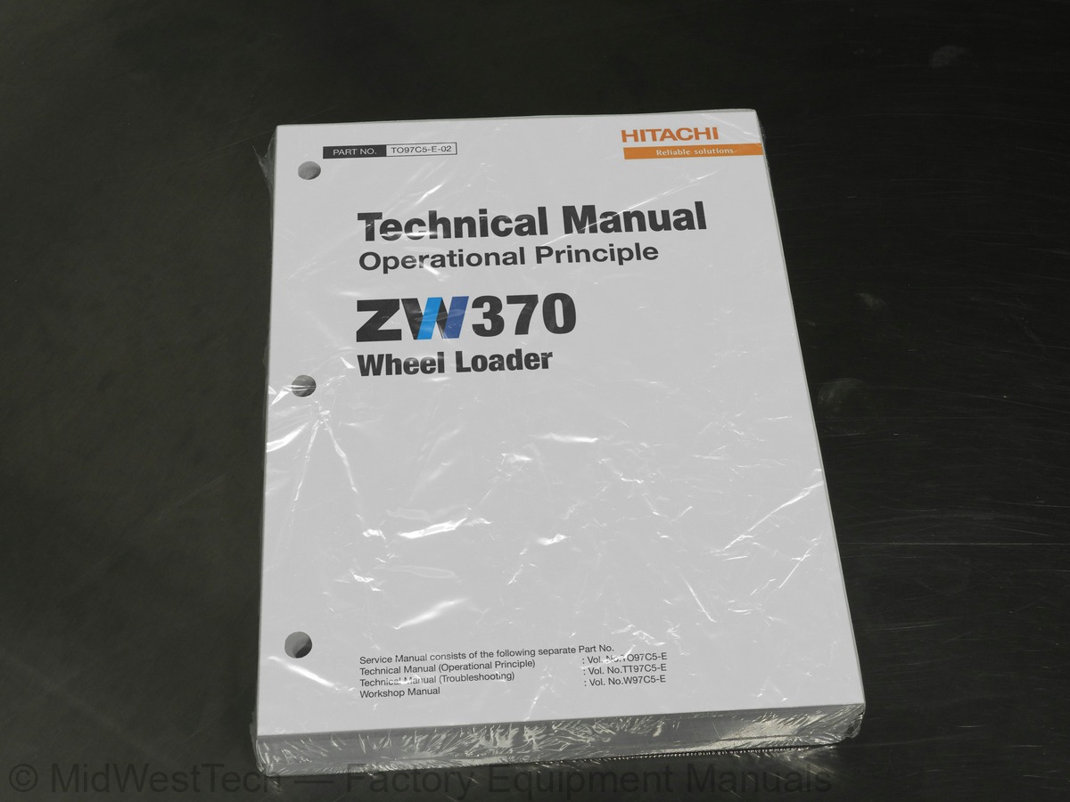
Hitachi ZW370 Wheel Loader Operational Principle Technical Service Manual
593 pages · Publication TO97C5-E-02
Added to your cart. View cart
- Models
- ZW370
- Manual type
- Operational Principle Technical Service Manual
- Pages
- 593
- Publication
- TO97C5-E-02
- Condition
- Brand new
What's inside
From the manual's own table of contents: 67 sections, 362 entries. See sample pages (PDF, 657 KB)
General32 topics
- General Information
- How to Use Manual
- Safety precautions
- Symbols
- Outline
- Layout of main components
- Inspection and maintenance table
- Recommended lubricants
- Coolant
- Lubrication chart
- Weight of main components
- Bolt tightening torque
- Hose band tightening torque
- Liquid gasket and screw lock agent
- Cautions regarding welding repair service
- Measurement for Performance Check
- Cautions on Safety
- Standard Measurement Values for Performance Check
- Function & Structure Chassis Group
- Front Chassis
- Loading linkage
- Loading linkage pin
- Rear Chassis
- Fuel tank
- Floor board mount
- Center Pin
- Upper center pin
- Lower center pin
- Dust seal
- Check & Adjustment Chassis Group
- Linkage Pin
- Liner
Center Pin3 topics
- Adjusting shim
- Grease nipple installation direction
- Installing bearing outer ring
Engine / Transmission1 topic
- Engine / transmission mount
Propeller Shaft2 topics
- Second propeller shaft assembly
- Third propeller shaft assembly
Torque Proportioning Type Differential Gear (TPD)2 topics
- Function of T.P.D
- Operation of T.P.D
Limited Slip Differential (LSD) (option)3 topics
- LSD structure
- LSD function
- LSD operation
Engine5 topics
- Measuring engine speed
- Measuring engine oil pressure
- Propeller shaft phase
- Second propeller shaft alignment
- Propeller shaft tightening torque
Axle33 topics
- Axle nut tightening procedure
- Differential gear adjustment procedure
- Function & Structure Torque Converter and Transmission Group
- Torque Converter
- Torque converter structure
- Power flow path
- Torque multiplication
- Torque Converter (Lock-up) (Option)
- Lock-up clutch structure
- Lock-up clutch function (only forward)
- Torque Converter Gear Pump
- Gear pump specifications
- Transmission
- Clutch combination
- Planetary gear
- Shift lever position
- Downshift button operation
- Gear train and number of teeth
- Clutch Pack
- Power Flow Path in the Transmission
- Forward 1st speed power flow path
- Forward 2nd speed power flow path
- Forward 3rd speed power flow path
- Forward 4th speed power flow path
- Reverse 1st speed power flow path
- Reverse 2nd speed power flow path
- Reverse 3rd speed power flow path
- Hydraulic System Diagram
- Hydraulic Circuit Diagram
- Oil Flow
- Oil flow in the torque converter line
- Oil flow to the clutch
- T/C and T/M Oil Circulation
Modulator Valve Unit3 topics
- Interior schematic (simple explanation)
- Modulator valve function
- Modulator valve operation
Control Valve Assembly3 topics
- Check valve
- Clutch solenoid valve assembly
- Clutch valve assembly
Clutch Oil Pressure and Time Lag2 topics
- Measuring clutch oil pressure
- Measuring clutch time lag
Flushing Hydraulic Circuit1 topic
- Purpose of flushing
Hydraulic Circuit Symbols8 topics
- Hydraulic lines
- Pumps & motors
- Cylinders
- Operation methods
- Pressure control valve
- Flow control valve
- Directional control valve
- Miscellaneous hydraulic symbols
Hydraulic System Operation1 topic
- Hydraulic system operation outline
Hydraulic Tank31 topics
- Hydraulic Tank (S/N 9301~)
- Hydraulic tank specifications
- Hydraulic oil level check
- Hydraulic Pump
- Loading and pilot and brake pump/Steering pump
- Loading and pilot and brake pump/Steering pump specifications
- Hydraulic pump principle
- Hydraulic pump wear plate
- Hydraulic pump bushing lubrication
- Hydraulic Cylinder
- Boom cylinder
- Bucket cylinder
- Steering cylinder
- Hydraulic cylinder specifications
- Loading System
- Reducing Valve (for Pilot Pressure)
- Multiple Control Valve (KML35A/2T003B)
- Multiple control valve specifications
- Multiple control valve main relief valve
- Multiple control valve overload relief valve (with make-up function)
- Multiple control valve make-up valve
- Multiple control valve bucket spool
- Multiple control valve boom spool
- Adapter (Orifice)
- Ride Control (OPT)
- Ride control hydraulic circuit
- Ride control operation
- Ride control valve assembly (Reducing valve circuit)
- Ride control valve assembly (Accumulator circuit)
- Accumulator (for ride control)
- Steering System
Show all 68 sections
Orbitrol ®7 topics
- Orbitrol ® structure
- Orbitrol ® specifications
- Orbitrol ® operation
- Orbitrol ® feed-back mechanism operation
- Steering speed and flow rate control
- Hydraulic pump oil amount and steering force
- Orbit rotor operation principle
Steering Valve (KVS32-A4.0/20)6 topics
- Steering valve operation
- Steering spool variable throttle
- Steering valve flow control spool
- Steering valve main relief valve
- Steering valve overload relief valve
- Steering pilot circuit and its operation
Stop Valve2 topics
- Stop valve function
- Stop valve operation
K-Lever (OPT)6 topics
- Hydraulic circuit
- Hydraulic line diagram
- Hydraulic line
- Solenoid valve mount
- Solenoid valve assembly (1/2)
- Solenoid valve assembly (2/2)
Efficient Loading System4 topics
- Efficient loading system outline
- Mounting of the ELS valve
- Mounting of the variable kickout sensor
- Efficient loading system operation
Fan Motor System33 topics
- Mounting of fan motor
- Fan Motor Line
- Hydraulic circuit (fan motor normal rotation)
- Proportional relief valve (S/N 9001~9150)
- Proportional relief valve (S/N 9151~)
- Fan motor
- Reversing Fan Motor Line (OPT)
- Reversing fan motor function
- Hydraulic circuit (Reverse rotation)
- Secondary Steering
- Secondary steering operation
- Secondary steering motor and pump
- Check & Adjustment Hydraulic Group
- Loading/Steering Circuit Relief Valve/Ride Control Circuit Reducing Valve (OPT)
- Loading circuit relief valve setting pressures
- Ride control circuit reducing valve setting pressures (OPT)
- Steering circuit relief valve setting pressures
- Cylinder natural drift
- Stop Valve
- Stop valve adjustment procedure
- Function & Structure Brake Group
- Brake System Outline
- Service brake
- Parking brake
- Adjustment of axle internal pressure
- Brake Units Layout
- Unloader Valve
- Unloader valve operation
- Valve Unit
- Accumulator
- Brake Valve
- Brake valve performance chart
- Brake valve outline
Service Brake6 topics
- Service brake operation
- Service brake friction plate
- Service brake steel plate
- Service brake piston
- Service brake pedal stroke adjusting mechanism (S/N 9001~9014)
- Brake circuit air bleeding procedure
Parking Brake4 topics
- Parking brake operation
- Parking brake friction plate
- Parking brake steel plate
- Parking brake solenoid valve
Auto Brake3 topics
- Auto brake circuit
- Auto brake operation set value
- Solenoid valve (for Autobrake circuit)
Pressure Sensor (for stop lamp and declutch)2 topics
- Pressure sensor (for declutch)
- Pressure sensor (for stop lamp)
Brake Circuit Oil Pressure6 topics
- Unloader valve setting pressure
- Brake valve oil pressure
- Service brake performance check
- Service brake friction plate wear measurement
- Cautions on installing brake discs
- Parking brake performance check
Verwendung des elektrischen Schaltplans (DEUTSCH)28 topics
- Modalità di utilizzo dello schema dei collegamenti elettrici (ITALIANO)
- Cómo utilizar un Diagrama de Alambrado Eléctrico (ESPAÑOL)
- Como Utilizar o Diagrama de Ligações Eléctricas (PORTUGUÊS)
- Electrical Cable Color Codes
- Electrical Circuit Symbols
- Sensor Mount
- Fuse
- Fuse box
- Fusible link
- Engine Start Circuit
- Engine start circuit diagram
- Neutral starter
- Starter switch
- Battery relay
- Alternator I terminal wire
- Diode unit
- Neutral relay
- Magnetic switch
- Voltage relay
- Power Generating/Charging Circuit
- Alternator
- ECM (Engine Controller)
- Function of ECM
- Connection diagram
- Monitor lamp test
- Failure diagnosis
- Quantum fault code information
- Accelerator pedal
Transmission Control Circuit and Monitor Circuit7 topics
- Machine control unit (MCU)
- Machine control unit (MCU) connection diagram (S/N 9001~9350)
- Machine control unit (MCU) connection diagram (S/N 9351~)
- Machine control unit (MCU) function
- Adjustable declutch preset switch
- Monitoring system
- Operation monitor lamps
Instrument Panel and Switch4 topics
- Instrument panel (S/N 9351~)
- Instrument panel rear surface
- Gauge circuit
- Fuel gauge circuit
MODM8 topics
- MODM function
- Monitor Changeover
- Information Monitor
- Replacement Monitor
- Fault Log Monitor
- Input/Output Monitor
- Parameter Setting Monitor
- Specification Setting Monitor
Electrical Detent Circuit5 topics
- Bucket leveler
- Detent solenoid
- Lift kickout & lower kickout
- Sensor assy
- Preset height adjustment
Diode33 topics
- Diode check method
- Caution for diode check method
- Surge voltage and surge suppression diodes
- Function & Structure Operator Station Group
- Cabin
- Glass
- Wiper mount
- Wiper motor
- Operator Seat
- Steering and Transmission Shift Lever
- Tilt case
- Column shaft
- Shift lever
- Air Conditioner
- Denso air conditioner components
- Denso air conditioner structure
- Function of cooling mechanism
- Cooling circuit
- Electrical circuit
- Air conditioner functions of components
- Charge of refrigerant
- Air conditioner troubleshooting
- Check & Adjustment Operator Station Group
- Adjustment of lubricating oil quantity when components of air conditioner are replaced
- Adjustment of air gap (between hub and rotor) in compressor magnetic clutch
- Compressor V-belt adjustment
- Parts to be replaced periodically
- Drawing & Diagrams
- Axle Assembly
- Torque Converter and Transmission
- Hydraulic & Brake Circuit (S/N 9001~9250)
- Hydraulic & Brake Circuit (S/N 9251~)
- Brake Circuit
Electrical Wiring Diagram1 topic
- Way of looking at connectors
Inside this manual
Real pages from this operational principle technical service manual (593 pages). Open the sample pages (PDF, 656 KB)
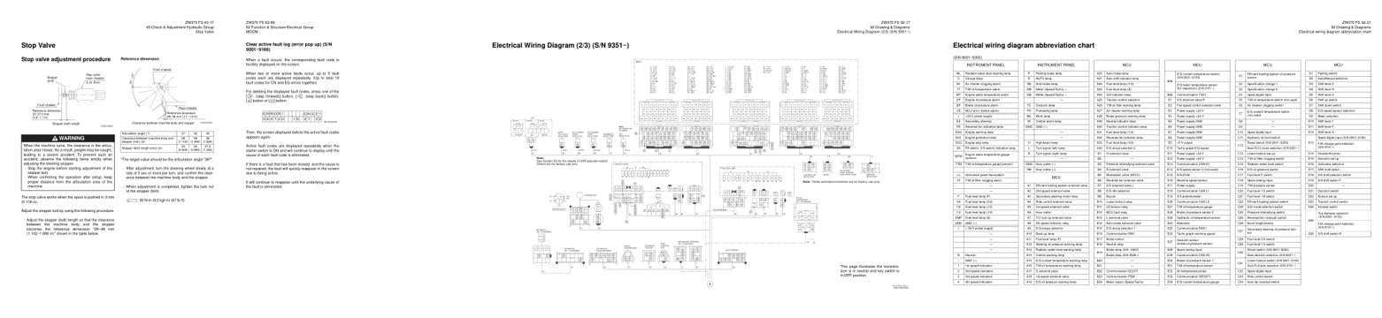
- Specifications, page 269: 43 Check & Adjustment Hydraulic Group
- Troubleshooting, page 404: 62 Function & Structure Electrical Group
- Diagram, page 539: 92 Drawing & Diagrams
- Foldout diagram, page 543: 92 Drawing & Diagrams
Other manuals for this machine
Save 10% on 2 manuals, 15% on 3 or more. Other manuals for the ZW370 are listed below. Editions cover different serial number ranges: check the serial coverage and tick only the ones that match your machine.
Added to your cart. View cart
Manual types
This manual is a operational principle technical service manual. For reference, the three main manual types:
Service manual
Factory repair procedures and technical information such as specifications, troubleshooting, and wiring and hydraulic diagrams, for the models and systems the manual covers. See What's inside for its topics.
Operator's manual
Safe operation, controls, maintenance schedules, lubrication points, inspections, and basic checks. Repair procedures are in the service manual.
Parts manual
Illustrated diagrams with factory part numbers for identifying components and ordering parts. Repair procedures are in the service manual.
Engine service manuals are sometimes sold separately, since certain machine models were offered with more than one engine option.
What it's used for
Factory manual for in-house farm and construction shop use. Straightforward, complete, and easy to follow. It contains the OEM information dealership service departments and parts counters use to diagnose problems, identify components, and perform maintenance or repairs correctly.
Service shops and owner/operators who repair their own equipment
Identifying correct parts and seeing how assemblies come apart and go back together
Keeping equipment running with less downtime
Factory manual, 593 pages
Quantity one is the manual described above.
Fast free USA shipping
Ships in 1 business day.
60-day returns
Free if the mistake is ours. A manual ordered in error must come back unopened in its shrink-wrap; you pay return shipping and a 20% restocking fee applies. Return policy
Binder not included
Manuals over about 300 pages may need a standard 3-ring binder, which you can buy locally to keep the pages organized for shop use.
Questions about model, serial number, engine coverage or contents? Contact us before purchasing and we'll help confirm it's the right manual. Please verify the manual type, machine model, serial number range and engine coverage before purchasing: manuals ordered in error carry a 20% restocking fee (return policy).