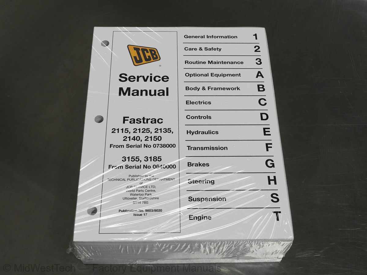
JCB Fastrac 2115, 2125, 2135, 2140, 2150 Tractor Service Manual
1,027 pages · Publication 9803-8020
Added to your cart. View cart
- Models
- Fastrac 2115, 2125, 2135, 2140, 2150
- Serial coverage
- from SN 0738000, from SN 0640000
- Manual type
- Service Manual
- Pages
- 1,027
- Publication
- 9803-8020
- Condition
- Brand new
What's inside
From the manual's own table of contents: 10 sections, 465 entries. See sample pages (PDF, 584 KB)
General Information19 topics
- Machine Identification Plate
- Typical Vehicle Identification Number (VIN)
- Typical Engine Identification Number
- Unit Identification
- Introduction - Zinc Plated Fasteners and Dacromet Fasteners
- Zinc Plated Fasteners
- Sealing and Retaining Compounds
- Service Tools Numerical List
- Body and Framework
- Electrics
- Hydraulics
- Transmission
- Brakes
- Steering
- Suspension
- Engine
- General
- Preparation for Towing
- Transporting the Machine
Care & Safety4 topics
- Safety Notices
- General Safety
- Operating Safety
- Maintenance Safety
Routine Maintenance80 topics
- Engine Oil - (All Machines)
- Lubricants & Capacities (2000 Series Machines)
- Lubricants & Capacities (3155)
- Lubricants & Capacities (3185)
- Lubricants - Health and Safety
- Service Schedules (Dry Clutch Transmission †)
- Service Schedules (Wet Clutch Transmission ††)
- Cleaning the Machine and Checking for Damage
- Checking Seat Belt Condition and Security
- Opening/Closing the Bonnet (2000 Series Machines)
- Opening/Closing the Bonnet (3000 Series Machines)
- Propshafts and PTO Driveshafts
- Steering Swivels (2000 Series Machines)
- Front Axle Steering Swivels (3000 Series Machines)
- Hydraulic Lift & 3 point Linkage (2000 Series Machines)
- Rear PTO Driveshaft Bearings (2000 Series Machines)
- Rear Suspension Cylinder Pivots (2000 Series Machines)
- Hydraulic Lift & 3 point Linkage (3000 Series Machines)
- Rear PTO Driveshaft Bearings (3000 Series Machines)
- Rear Suspension Cylinder Pivots (3000 Series Machines)
- Rear Anti-roll Bar Ball Joints (2000 Series Machines)
- Steering Box Input Shaft Seal (3000 Series Machines)
- Rear Anti-roll Bar Ball Joints (3000 Series Machines)
- Automatic Trailer Coupling (if fitted)
- Checking the ROPS Structure
- Checking the Windscreen Washer Fluid Level
- Cleaning the Filter (2000 Series Machines)
- Cleaning the Filter (3000 Series Machines)
- Adjusting the Compressor Belt (2140 and 3000 Series)
- Battery Warning Symbols
- First Aid - Electrolyte
- Checking the Battery Electrolyte Level
- Checking the Headlight Beam Alignment
- Checking the Fluid Level
- Changing the Filter Element
- Changing the Hydraulic Fluid and Cleaning the Suction Strainer
- Emptying the Hydraulic Coupling Drain Reservoir (if fitted)
- Checking the Oil Level
- (Dry Clutch Transmission) †
- Changing the Transmission Oil Filter
- Checking the Front PTO Gearbox Oil Level (if fitted)
- Checking the Differential Oil Level
- Changing the Differential Oil
- Checking the Hub Oil Levels
- Changing the Hub Oil
- Changing the Oil
- Checking 4WS Right Side Trunnion Seals
- Tyre Inflation
- Checking and Adjusting Wheel Alignment
- Track Width
- Checking Wheel Nut Torques
- Lock Stops
- Fender Adjustment
- Checking and Renewing Foot Brake Pads
- Checking and Renewing the Parking Brake Pads
- Checking the Foot Brake Fluid Level (2000 Series Machines)
- Draining the Air System Tank (2000 Series Machines)
- Checking the Foot Brake Fluid Level (3000 Series Machines)
- Draining the Air System Tank (3000 Series Machines)
- Exhaust Brake (if fitted) (3185 Machines only)
- Changing the Oil and Filter
- Draining/Cleaning the Fuel Sediment Bowl
- Draining/Renewing Fuel Pre-Filter (when fitted)
- Draining the Fuel Filters
- Changing the Fuel Filter Elements
- Bleeding the Fuel System (3185)
- Cleaning the Fuel Tank Strainer (Early machines only)
- Checking the Coolant Level
- Coolant Mixtures
- Draining & Refilling the Coolant (3155 Machines)
- Draining & Refilling the Coolant (2140 and 3185 Machines)
- Cleaning the Radiator (2000 Series Machines)
- Cleaning the Radiator (3000 Series Machines)
- Cleaning the Pre-Cleaner (optional)
- Adjusting the Fan Belts (Machines Except 3185)
- Adjusting the Fan Belt (2140)
- Adjusting the Fan Belt (3185)
- Changing the Air Filter Elements (Early 2000 Series)
- Changing the Air Filter Elements (Later 2000 Series)
- Changing the Air Filter Elements (3000 Series)
Body and Framework27 topics
- Air Conditioning system
- Direct Glazing
- Prepare for Removal - All Machines
- Removal - 2000 Series Machines
- Removal - 3000 Series Machines
- Replacement- All Machines
- Installation Diagram
- Introduction
- System Operation
- System Protection Devices
- Operator Controls
- Safety Procedures
- Refrigerant Type
- Leak Testing
- Hoses and Pipes
- Component Removal and Replacement
- Electrical Circuit - Description
- Electrical Circuit Testing - General
- Pressure Switch Testing
- Operation
- Control
- Testing
- Removal and Replacement
- Heater System (3000 Series Machines)
- Early Machines
- Later Machines
- Compressor Clutch - Removal and Replacement
Electrics155 topics
- General Data
- Fuses
- Relay Identification
- Use of Multimeter
- Measuring DC Voltage
- Measuring Resistance
- Measuring Continuity
- How to Test a Diode or a Diode Wire
- Introduction to Sectional Wiring Diagrams
- Main Connectors (2140)
- Connector Terminals (2140)
- Splice Identification (2140)
- Alphabetical Index (2140)
- Component Key (2140)
- Sectional Diagrams (2140)
- Wire Numbers (2140)
- Starting Circuit
- Charging Circuit Test
- Tachometer Feed Test
- Wiring Harness Repair
- Safety
- Battery Testing
- General Description
- Service Precautions
- Dismantling and Assembly
- Dismantling
- Service and Renewal
- Assembly
- Warnings (Visual only)
- Warnings (Audible/Visual)
- Instruments
- Programming
- Error Codes - Transmission
- Error Codes - Anti-skid Braking System (ABS)
- JCB Powershift
- Wheel Slip Calibration
- Powershift Clutch Overlap Time (†Dry Clutch Transmission)
- (††Wet Clutch Transmission)
- Psion Workabout
- Calibration
- Bulb Renewal
- Diagnostic Error Codes - General
- Electronic Service Tools Applications
- JCB Service Master
- Data Link Adaptor
- ABS Diagnostics Tool
- Wingst Program
- Engine Diagnostic Tool
- Supply Circuit
- Earth Circuit
- Fuse C9 - Air Drier; Neutral Start (Gearbox)
- Fuse A2 - Brake Lights
- Fuse A3 - Rear Wash/Wipe
- Fuse A4 - Front Wash/Wipe; Horn
- Fuse A4 (cont’d)
- Fuse A5 - Engine Shut-Off Solenoid (E.S.O.S.) (2000 Series, 3155 Wet Clutch Transmission)
- Fuse A5 - Engine Shut-Off Solenoid (E.S.O.S.) (3185 only) - E.S.O.S. Maxifuse
- Fuse B9 - Electronic Draft Control (EDC) B, Battery Cab Side
- Fuse B9 - Electronic Draft Control (EDC) D+ and B, Battery Chassis Side
- Fuse A7 - Powershift ECU - 3-Speed Splitter (Dry Clutch Transmission)
- Fuse A7 (cont’d) - Wet Clutch Control (Wet Clutch Transmission)
- Fuse A7 (cont’d) - Powershift ECU - Selectronic
- Fuse A8 - Front/Rear PTO; 2WD and Differential Lock Solenoids; Rear PTO Cut-Out
- Rear PTO Cut-Out Option
- Fuse A9 - Air Conditioning Circuit
- Fuse B1 - Interior Lights; Radio/Cassette; Beacon Socket
- Fuse C2 - Direction Indicators
- Fuse B3 - Front Work Lights
- Fuse B4 - Rear Work Lights
- Fuse W (Maxifuse) - Main Lights
- Fuse D2 - Dipped Beam
- Fuse D3 - Rear Fog Lights
- Fuse D4 - Side Lights (Left Side)
- Fuse D5 - Side Lights (Right Side)
- Auxiliary Lights Switching (2000 Series)
- Fuse D6 - Auxiliary Lights Switching (3000 Series)
- Fuse B6 - Radio Cassette
- Fuse B7 - Auxiliary Jack-Plug Socket
- Fuse B8 - Cigar Lighter
- Fuse C1 - Reverse Lights (Wet Clutch Transmission)
- Fuse C3 - Thermostart
- Connector; Speedo Sensor; Fuse C5 (Dry Clutch Transmission)
- Fuse C4 (Wet Clutch Transmission) (cont’d)
- Fuse C4 (cont’d) - Canbus; Diagnostic Connector
- Fuse C5 - Fuel Flow Sensor; Ground Speed Radar Sensor (Wet Clutch Transmission)
- Fuse C8 - 13-pin Trailer Socket (Battery)
- Fuses F1, F2, F3, F4 - Tractor ABS
- Fuse E3 - Flow Divider
- Fuse E4 - Four Wheel Steer (4WS) Circuit
- Section C
- Dealer Requirements
- Installation of Psion and Fastrac Software
- Using the Fastrac Software
- Set-up Menu Options
- Set-up from Vehicle Type
- Set-up from VIN
- Level ‘0’ Menu
- Level ‘1’ Menu
- Level ‘2’ Menu
- Level ‘3’ Menu
- Special Menu Option
- Save Settings
- Logging Main Menu Options
- Download Data Log
- Download Data Log Menu Options
- Comm Menu
- View Menu
- Filter Menu
- Special Menu
- Erase Datalog Memory Option
- Load File Option
- Wet Clutch ††
- Special Main Menu Options
- EMS Information
- Preferences
- About
- Exit
- Error Codes
- Factory Default Settings
- Equipment Required
- Installation of the Software
- Connecting the PC to the Fastrac
- Starting the Program
- Main Screen Menu
- File
- Delete Files
- Exit Files
- Edit
- Copy
- Setup
- Setup from Vehicle Type
- Setting from VIN
- Programme Specific Items
- Level 1
- Level 2
- Level 3
- Load Settings
- Reload Transmission EEPROM
- Update EMS Software
- Data Logging
- Filter
- Fault Description
- Erase Datalog Memory
- Load File
- Window
- Glossary of Data Log Terms
- Diagnostics
- Values
- Inputs
- Outputs
- LED Inputs
- Wet Clutch
- Pedal
- Misc
- Help
Section D11 topics
- Technical Data
- Adjustment
- Lever Linkages - Removal and Replacement
- Flow Control Linkages
- Setting Flow Control
- System Description
- Limp Home Mode
- Renewing Microswitches
- Setting Range Gearbox Turret Stops
- Setting Cylinder Rod Neutral Lengths
- Setting Microswitch Positions
Section E31 topics
- Series Machines
- Flow Regulator Valves
- Neutral Circuit
- Three Position Spool (D Type)
- Four Position Spool
- Main Relief Valve (MRV) Type 1†
- Main Relief Valve (MRV) Type 2 ††
- Spool and Detent - Dismantling and Assembly
- Flow Control Valve - Dismantling and Assembly
- Poppet Valve - Dismantling and Assembly
- Main Relief Valve - Dismantling and Assembly
- Solenoids - Dismantling and Assembly
- Pressure Compensator - Dismantling and assembly
- Internal Check Valve - Dismantling and Assembly
- Dismantling and Assembly
- Removing the Non- return Valves
- Replacing the Non- return Valves
- Locking the Spool in Neutral
- Repairing the Check Valves
- Diverter Valve - Dismantling and Assembly
- Solenoid Valves - Dismantling and Assembly
- Dismantling and Assembly
- System Activation Procedure
- Hydraulic Circuit Operation
- Functional Test of Control Valve
- Arms Cannot be Raised or Lowered
- Fault Diagnosis
- Control Valve - Removal and Replacement
- Draft Pin - Removal and Replacement
- Removal and Replacement/Setting
- Section E
Section F60 topics
- General Description - †Dry Clutch Transmission
- General Description - ††Wet Clutch Transmission
- Complete Transmission
- Wet Master Clutch
- Power Take Off Clutches
- 4/2 Wheel Drive
- Differential Lock
- Gearbox - †Dry Clutch Transmission
- Gearbox - ††Wet Clutch Transmission
- Powershift
- Powershift Clutches
- Transmission Brake (if applicable)
- Wet Master Clutch (if applicable)
- Control Valve - †Dry Clutch Transmission
- Removal, Replacement
- Dismantling, Assembly
- Pressure Maintenance Valve
- Lubrication Pressure
- Control Valve - ††Wet Clutch Transmission
- Differential Lock Control Valve
- Powershift Solenoid Valve
- Solenoid Valve
- Wet Clutch Control Valve (if applicable)
- Removal, Inspection and Replacement
- Clutch Pedal Adjustment
- Booster Operation
- Bleeding
- Clutch Booster
- Clutch Slave Cylinder
- Shim Calculation
- Main Drive Clutch Check Valve (if fitted)
- Potentiometer (Position Sensor)
- †Dry Clutch Transmission
- ††Wet Clutch Transmission
- Housing Removal and Replacement
- Dismantling and Assembly
- Removal and Replacement
- Dismantling and Assembly
- Removing and Dismantling
- Housing - ††Wet Clutch Transmission
- Dismantling and Assembly
- Removal and Replacement
- Layshaft Bearing Preload
- End Float Check
- Dismantling and Assembly
- Removing and Replacing
- Replacing Brake Caliper Wear Bushes
- Fitting Procedure
- Pressure Testing - 4-Wheel Drive Clutch
- Syncromesh Assembly
- Checking for Damage or Distortion
- Description
- Pinion Depth
- Solid Spacer Installation
- Crown Wheel and Pinion Adjustment
- Removal and Replacement
- Drive Head - Dismantling
- Drive Head - Assembly
- Dismantling and Assembly
- Rear PTO Output Shaft
Section G55 topics
- Brake System - General
- Brake System (Dry) (Non ABS)
- Brake System (Wet)
- Tractor ABS System (if fitted)
- Fault Finding
- Caliper Configuration
- Removal and Replacement
- Brake System Bleeding
- Dismantling and Assembly
- Removal and Replacement
- Dismantling and Assembly
- Removal and Replacement
- Dismantling and Assembly
- Removal and Replacement
- Testing (in-situ)
- Dismantling and Assembly
- Bench Testing
- Dismantling and Assembly
- Testing
- Removal and Replacement
- Dismantling and Assembly
- Removal and Replacement
- Dismantling and Assembly
- Removal and Replacement
- Dismantling and Assembly
- Actuator Cylinder
- Removal and Replacement
- Dismantling and Assembly
- Bench Testing
- Removal and Replacement
- System Features
- Steer Mode Selection
- JCB Headland Management System (HMS)
- Operation 1 - Neutral
- Operation 2 - Left Turn
- Operation 3 - Right Turn
- Operation 4 - Left Turn, Unassisted
- Operation 5 - Pressure Relief Valve
- All Machines (Fastrac 2000 Series)
- Diagnosis
- Diagnostic LED’s
- Pressure Testing (Fastrac 2000 Series)
- Removal and Replacement
- Dismantling and Assembly
- Removal and Replacement
- Dismantling and Assembly
- Dismantling/Removal
- Assembly/Replacement
- Removal and Replacement
- Setting the Relief Valves
- Dismantling and Assembly
- Removal and Replacement
- Dismantling and Assembly
- Ball Joints, Removal and Replacement
- Power Track Rod, Dismantling and Assembly
Steering13 topics
- Steering System Description (Fastrac 3000 Series)
- Fault Finding (Fastrac 3000 Series)
- Pressure Testing (Fatrac 3000 Series)
- Limit Valve Setting
- Fitting the Input Shaft Nut and Star Nut
- Checking
- Description and Hydraulic Circuit Diagram
- Pressure Testing
- Ride Height
- Discharging Hydraulic Pressure
- Ball Joint - Dismantling and Assembly
- Fuel System
- Fastrac 3155
Inside this manual
Real pages from this service manual (1,027 pages). Open the sample pages (PDF, 583 KB)

- Specifications, page 374: Start the engine and run at maximum speed (see Technical
- Troubleshooting, page 464: Issue 4
- Diagram, page 944: ACTION
- Color page, page 491: Section C
- Color page, page 79: Battery Warning Symbols
- Foldout diagram, page 308: Electrics
This is a service manual
Here's how it compares to the other manual types.
Service manual
Factory repair procedures and technical information such as specifications, troubleshooting, and wiring and hydraulic diagrams, for the models and systems the manual covers. See What's inside for its topics.
Operator's manual
Safe operation, controls, maintenance schedules, lubrication points, inspections, and basic checks. Repair procedures are in the service manual.
Parts manual
Illustrated diagrams with factory part numbers for identifying components and ordering parts. Repair procedures are in the service manual.
Engine service manuals are sometimes sold separately, since certain machine models were offered with more than one engine option.
What it's used for
Factory manual for in-house farm and construction shop use. Straightforward, complete, and easy to follow. It contains the OEM information dealership service departments and parts counters use to diagnose problems, identify components, and perform maintenance or repairs correctly.
Service shops and owner/operators who repair their own equipment
Identifying correct parts and seeing how assemblies come apart and go back together
Keeping equipment running with less downtime
Factory manual, 1,027 pages
Quantity one is the manual described above.
Fast free USA shipping
Ships in 1 business day.
60-day returns
Free if the mistake is ours. A manual ordered in error must come back unopened in its shrink-wrap; you pay return shipping and a 20% restocking fee applies. Return policy
Binder not included
Manuals over about 300 pages may need a standard 3-ring binder, which you can buy locally to keep the pages organized for shop use.
Questions about model, serial number, engine coverage or contents? Contact us before purchasing and we'll help confirm it's the right manual. Please verify the manual type, machine model, serial number range and engine coverage before purchasing: manuals ordered in error carry a 20% restocking fee (return policy).