JCB Fastrac 2155, 2170 Tractor Service Manual
909 pages · Publication 9803-8050
Added to your cart. View cart
- Models
- Fastrac 2155, 2170
- Manual type
- Service Manual
- Pages
- 909
- Publication
- 9803-8050
- Condition
- Brand new
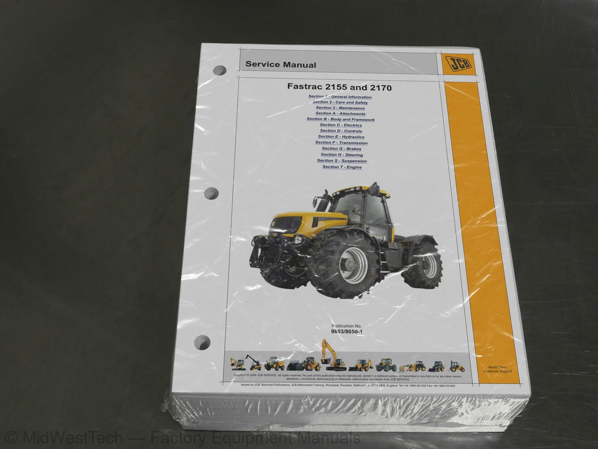
What's inside
From the manual's own table of contents: 7 sections, 448 entries. See sample pages (PDF, 376 KB)
General72 topics
- Serial Numbers
- Serial Number Plate
- Numerical List
- Tool Detail Reference
- Section B - Body and Framework
- Section C - Electrics
- Section E - Hydraulics
- Section F - Transmission
- Section G - Brakes
- Section H Steering
- Section S - Suspension
- Sealing and Retaining Compounds
- Zinc Plated Fasteners and Dacromet Fasteners
- Introduction
- Zinc Plated Fasteners (golden finish)
- Dacromet Fasteners (mottled silver finish)
- Hydraulic Connections
- O' Ring Face Seal System
- Torque Stop' Hose System
- Important Information
- The Operator Manual
- Safety Warnings
- Safety First
- Safety - Yours and Others
- General Safety
- Operating Safety
- Maintenance Safety
- Service Requirements
- Owner/Operator Support
- Service/Maintenance Agreements
- Initial Service and Inspection (100 Hours)
- Obtaining Replacement Parts
- Health and Safety
- Lubricants
- Battery
- First Aid - Electrolyte
- Service Schedules
- How to Use the Service Schedules
- Service Schedule Tables
- Fluid, Lubricants and Capacities
- Coolant Mixtures
- Cleaning the Machine
- Checking for Damage
- Seat Belt
- Checking the ROPS Structure
- Engine Cover
- Opening the Engine Cover
- Closing the Engine Cover
- Greasing
- Propshafts and PTO Drive Shafts
- Steering Swivels
- Rear Anti-roll Bar Ball Joints
- Rear Suspension Cylinder Pivots
- Front 3-Point Linkage
- Hydraulic Lift and 3-Point Linkage
- Rear PTO Drive Shaft Bearing
- Automatic Trailer Coupling (if fitted)
- Roller Drawbar (If fitted)
- Air Conditioning and Heater
- Air Conditioning Filters
- Cleaning the Heater Filter
- Brakes
- Checking the Foot Brake Fluid Level
- Checking the Trailer Air Tank
- Checking the Air Tank Warning Lights
- Checking and Renewing Foot Brake Pads
- Checking the Park Brake Pads
- Electrical
- Jump-starting the Engine
- Checking the Beam Alignment
- Fuses
- Relay Identification
Section 3 - Maintenance98 topics
- Engine
- Changing the Air Filter Elements
- Checking the Oil Level
- Changing the Oil and Filter
- Checking the Coolant Level
- Draining and Refilling the Coolant
- Cleaning the Radiator and Coolers
- Fan Belt
- Fuel System
- Types of Fuel
- Advice
- Filling the Tank
- Draining the Fuel Pre-Filter
- Changing the Fuel Pre-Filter Element
- Changing the Fuel Filter Element
- Bleeding the Fuel System
- Hydraulic System
- Checking the Fluid Level
- Changing the Filter Element
- Changing the Hydraulic Fluid and Cleaning the Suction Strainers
- Coupling Drains
- Transmission
- Checking the Gearbox Oil Level
- Changing the Gearbox Oil and Suction Strainer
- Changing the Transmission Oil Filter
- Front PTO Transfer Gearbox (Optional)
- Front Axle
- Rear Axle - 2WS
- Rear Axle - 4WS (Optional)
- Tyres and Wheels
- General
- Tyre Inflation
- Checking Wheel Nut Torques
- Adjustable Track Width
- Lock Stops
- Checking and Adjusting the Wheel Alignment
- Fender Adjustment
- Windscreen Washer
- Checking Fluid Level
- Automatic Trailer Coupling (Optional)
- Checking for Wear
- Hydraulic Units
- Litre Flow Regulator
- Transfer Box
- Dismantling and Assembly
- Fitting the Front PTO Output Shaft
- Flow Testing and Pressure Testing
- Prepare the Machine
- Flow Testing
- Relief Valve Pressure Testing
- Dismantling
- Assembly
- Engine Heater
- Removal and Replacement
- Range Gearbox Heater/Thermostat
- Using a Multimeter
- Measuring DC Voltage
- Measuring Resistance
- Measuring Continuity
- Measuring Frequency
- Testing a Diode or a Diode Wire
- Maintenance
- Testing
- Specific Gravity Testing
- Why Use Service Master?
- Fault Finding
- Identify Poor Maintenance
- Access Machine Set Up Data
- Re-Programming ECUs
- Summary
- What is Service Master?
- CANbus Communications System
- Service Master Structure
- How to Set Up Service Master
- Install Service Master
- Start Service Master
- Load the DLA Laptop Driver Software
- Configure the DLA Type and Communications Port
- Check the DLA Firmware File
- Connect Service Master to the Machine CANbus
- Diagnostic Tools
- Warnings (Visual only)
- Warnings (Audible/Visual)
- Instruments
- Instrument Cluster Programming
- Level `0' Programming Mode (Normal Operation)
- Level 1 Programming Mode
- Level 1 Programming Mode (continued)
- JCB Powershift
- Manual Operation
- Autoshift (Automatic) Operation
- Powershift and Master Clutch Calibration
- Calibration
- Wheel Slip
- Slip Control Re-calibration
- Slip Control - Normal Operations
- 2WS Machines with Mechanical Spool Valves
- 4WS Machines with Electronic Spool Valves
Section C - Electrics46 topics
- To Calibrate Spool Valve Controls
- To Access the Spool Valve Controls Calibration Mode
- Calibration Mode
- To Configure Spool Valve Slices
- To Access the Configuration Mode
- Valve Slices Currently Configured
- To Configure `Bosch' Slices to a 2000 Series Fastrac
- ECU 1 Suspension Calibration
- To Access the Suspension Calibration Mode
- ECU 4 Suspension Calibration
- 4WS Sensors
- Removal
- Replacement
- 4WS Calibration
- Before Entering Calibration
- To Access the 4WS Calibration Mode
- Wire and Harness Number Identification
- Wire Numbers and Functions
- Harnesses and Interconnection
- Main Chassis Harness
- Main Cab Harness
- Transmission Harness
- 4WS and Electronic Spool Valve Harness, Cab
- 4WS and Electronic Spool Valve Harness, Chassis
- 2WS Harness, Cab, ECU4 (Mechanical Spool Valve)
- 4WS Harness, Cab (Mechanical Spool Valve)
- 4WS Harness, Chassis (Mechanical Spool Valve)
- ABS Harness, Chassis 2WS
- ABS Harness, Chassis 4WS
- ABS Harness, Cab (2WS and 4WS)
- Auxiliary Light Harness
- Auxiliary Power Output Harness
- Drawings
- Wiring Harness Repair
- Repair Procedure
- Number Error Codes
- Blink Codes
- Fault Finding Tables
- General Codes (C and D)
- 4WS Codes (F)
- Engine Codes (Q)
- Suspension Codes (S)
- Transmission Codes (T)
- Spool Valve Codes (V, W, X, Y and Z)
- ABS Code Tables
- Electronic Draft Control
Section D - Controls51 topics
- JCB Selectronic
- Pneumatic Cylinders
- Microswitches
- Solenoid Valves
- Pressure Regulator
- Control Valve Linkage
- Lever Linkages
- Flow Control Linkages
- Speed Selector Cable
- System Description
- Selector Switch
- Indicators
- Operation
- Selecting a Forward Range
- Selecting Reverse Range
- Auto-shuttle
- Invalid or Incomplete Range Changes
- Electrical/Pneumatic Circuit Description
- Limp Home Mode
- Renewing Microswitches
- Setting Up
- Setting Microswitch Positions
- Field Speed Control
- Adjustment
- External Hydraulics
- Control Valve - Mechanically Actuated
- Control Valve - Electronically Actuated
- Other Hydraulic Circuits
- Component Location and Neutral Circuits
- Rear Electronic Draft Control
- Introduction to Hydraulic Schematic Symbols
- General (Basic and Functional Symbols)
- Control Valves
- Example of Schematic Circuit
- Schematic Circuits
- Hydraulic Circuit - with Mechanically Actuated Spool Valve
- Hydraulic Circuit - with Electronically Actuated Spool Valve
- Neutral Circuit with Mechanically Actuated Spool Valve
- Flow Regulator Valve
- External Hydraulics/Draft Control
- Spool Valves
- Mechanically Actuated Spool Valve
- Electronically Actuated Spool Valve
- Functional Test of Control Valve
- Main Relief Valve (MRV) - 2155 Plus, 2170 Plus
- Electronic Control Valve Pilot Pressure
- Pump - Suspension and Steering
- Pump - Transmission and External Hydraulics
- Draft Sensor
- Position Sensor
- Replacement and Setting
Section E - Hydraulics40 topics
- Spool and Detent Section
- Flow Control Valve Section
- Input section - Main Relief Valve
- Input section - Diverter Valve
- Draft Control Valve - Solenoid Valves
- Draft Control Valve - Pressure Compensator
- Draft Control Valve - Internal Check Valve
- Draft Control Valve - Check Valve, Body, Seals and Plugs
- Precautions During Use
- Installation
- Caution During Use
- Maintenance, Inspection Points
- Front Hitch Ram
- Rear Lift Ram
- Clutches and Gearboxes
- Master Clutch
- Power Take-off Gearbox (PTO)
- Speed Gearbox
- Range Gearbox
- Transmission Hydraulics
- Pump
- Control Valve
- Differential Lock Control Valve
- Axles
- Rear Axle
- Complete Transmission
- NoSPIN Differential (Front Axle)
- Gearbox Hydraulic Circuit
- Powershift
- Differential Lock Hydraulic Circuit
- Complete Transmission, Clutches, Gearboxes and Axles
- Wet Master Clutch
- Power Take Off Clutches
- 4/2 Wheel Drive
- Differential Lock
- Powershift Clutches
- Transmission Brake
- Transmission Accumulator
- Pressure Maintenance Valve
- Lubrication Pressure
Section F - Transmission75 topics
- Clutch Drum and Hub
- Clutch Plates and Plate Carrier
- Clutch Drum Carrier and PTO Input gear
- Clutch Down Switch and Potentiometer
- Clutch Down Switch
- Potentiometer (Position Sensor)
- PTO Clutches
- Six-Speed Gearbox/Rear Housing
- PTO Clutches, Front and Rear
- Front PTO Clutch
- Rear PTO Clutch
- Splitter Clutches
- Speed Selector Shaft Assembly
- Output Section
- Idler Gear
- Removal and Dismantling
- Housing
- Replacing
- Remote Control
- Rear Housings
- Front Oil Seal and Housing
- Input Shaft, Mainshaft and Layshaft
- Layshaft Bearing Preload
- Mainshaft
- Layshaft
- Selector Shaft and Forks
- Removal (with Cab in Place)
- Front Casing
- Brake Calliper Bracket
- Clutch and Gear Assemblies
- 4-Wheel Drive Clutch
- Input Shaft
- Output Shaft
- Inspection Prior to Assembly
- Differential Oil Seal
- Front Axle and Rear 4WS Axle
- Hub and Drive Shaft
- Drive Head
- Maxtrac Differential
- NoSPIN Differential
- Differential
- Rear PTO Drive Shaft
- Rear PTO Output Shaft
- Main Control Valve
- Powershift Control Valves
- Wet Clutch Transmission Brake Solenoid Valve
- Wet Clutch Lubrication Control Valve
- Solenoid Valve
- Wet Clutch Control Valve
- Checking for Damage or Distortion
- Brake System
- Parking Brake
- Foot (Service) Brake
- All Machines
- Brake System (non ABS)
- Front Brake Circuit
- Rear Brake Circuit
- Trailer/Parking Brake Circuit
- Parking Brake Circuit
- Tractor Services Circuit
- Hydraulic Trailer Brakes (if fitted)
- Brake System (ABS)
- Tractor ABS System (if fitted)
- General Description
- Fault Tables
- Low Pressure Warning Lights On
- Service Brakes Poor
- Poor Front Brakes, Good Rear Brakes (Non-ABS Machines)
- Poor Front Brakes, Good Rear Brakes (ABS Machines)
- Poor Rear Brakes, Good Front Brakes (Non-ABS Machines)
- Poor Rear Brakes, Good Front Brakes (ABS Machines)
- Trailer Brakes Poor
- Park Brake Not Holding
- Park Brake Not Releasing
- Brake System Bleeding
Section G - Brakes35 topics
- When Dismantling
- Inspection
- When Assembling
- Air Dryer/Unloader Valve
- Circuit Protection Valve
- Pressure Modulating Valve
- Foot Brake Air Valve
- Non-Return Air Valve
- Failure Conscious PRV (Non-ABS Machines only)
- Trailer Brake Air Valve
- Trailer Brake Hydraulic Valve
- Testing (in Situ)
- Torque Settings
- Bench Testing
- Pressure Settings
- Two-Wheel Steer Machines
- Four-Wheel Steer Machines
- Front Axle Steering
- Operation 1 - Neutral
- Operation 2 - Left Turn
- Operation 3 - RIght Turn
- Operation 4 - Left Turn, Unassisted
- Operation 5 - Pressure Relief Valve
- Four-Wheel Steering
- Steer Mode Selection
- Heavy Steering
- Steering Wander or Free Play
- Rear Axle (4WS)
- Diagnosis
- Steering System Operating Pressure
- Steering Unit relief Valve
- Front Axle Steer Ram
- Rear Axle Steer Ram
- Steering Valve
- Setting the Relief Valve
Section H - Steering24 topics
- Power Track Rod
- Ball Joint Removal and Replacement
- Rear Suspension
- Pressures
- Description
- Shock Absorber (D)
- When Replacing
- Control Arm (A)
- Panhard Rod and Anti-roll Bar
- Panhard Rod (B)
- Anti-roll Bar (E)
- Coil Spring and Microcellular Spring
- Electronic Control
- Pressure Testing
- Discharging Hydraulic Pressure
- Machines with ECU 1
- Machines with ECU 4
- Potentiometer
- Potentiometer Operating Link
- Accumulator and Gas Spring
- Suspension Cylinder
- Anti-roll Bar
- Control Arm (J)
- `V' Link
Inside this manual
Real pages from this service manual (909 pages). Open the sample pages (PDF, 375 KB)
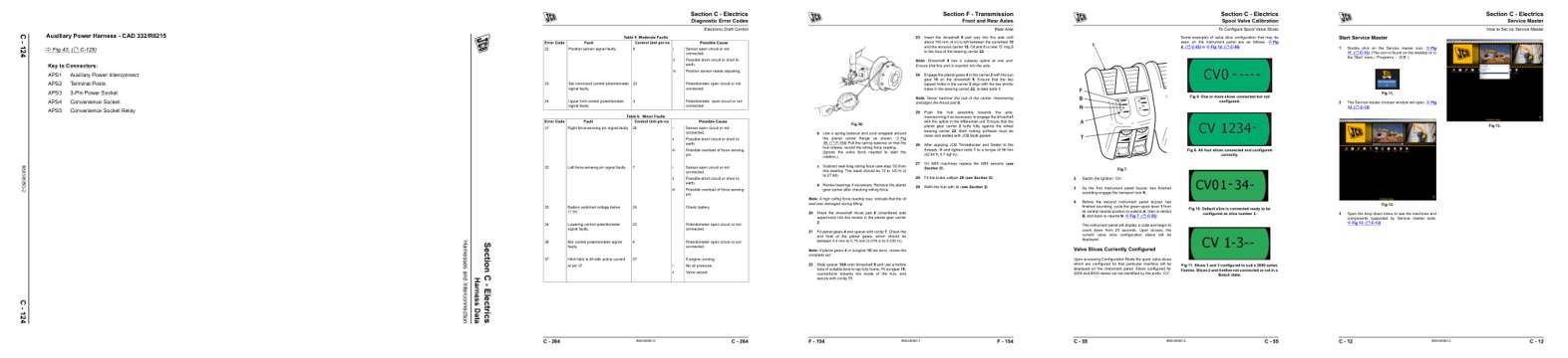
- Diagram, page 305: Harness Data
- Troubleshooting, page 445: Diagnostic Error Codes
- Specifications, page 725: Section F - Transmission
- Color page, page 236: Section C - Electrics
- Color page, page 193: Section C - Electrics
This is a service manual
Here's how it compares to the other manual types.
Service manual
Factory repair procedures and technical information such as specifications, troubleshooting, and wiring and hydraulic diagrams, for the models and systems the manual covers. See What's inside for its topics.
Operator's manual
Safe operation, controls, maintenance schedules, lubrication points, inspections, and basic checks. Repair procedures are in the service manual.
Parts manual
Illustrated diagrams with factory part numbers for identifying components and ordering parts. Repair procedures are in the service manual.
Engine service manuals are sometimes sold separately, since certain machine models were offered with more than one engine option.
What it's used for
Factory manual for in-house farm and construction shop use. Straightforward, complete, and easy to follow. It contains the OEM information dealership service departments and parts counters use to diagnose problems, identify components, and perform maintenance or repairs correctly.
Service shops and owner/operators who repair their own equipment
Identifying correct parts and seeing how assemblies come apart and go back together
Keeping equipment running with less downtime
Factory manual, 909 pages
Quantity one is the manual described above.
Fast free USA shipping
Ships in 1 business day.
60-day returns
Free if the mistake is ours. A manual ordered in error must come back unopened in its shrink-wrap; you pay return shipping and a 20% restocking fee applies. Return policy
Binder not included
Manuals over about 300 pages may need a standard 3-ring binder, which you can buy locally to keep the pages organized for shop use.
Questions about model, serial number, engine coverage or contents? Contact us before purchasing and we'll help confirm it's the right manual. Please verify the manual type, machine model, serial number range and engine coverage before purchasing: manuals ordered in error carry a 20% restocking fee (return policy).