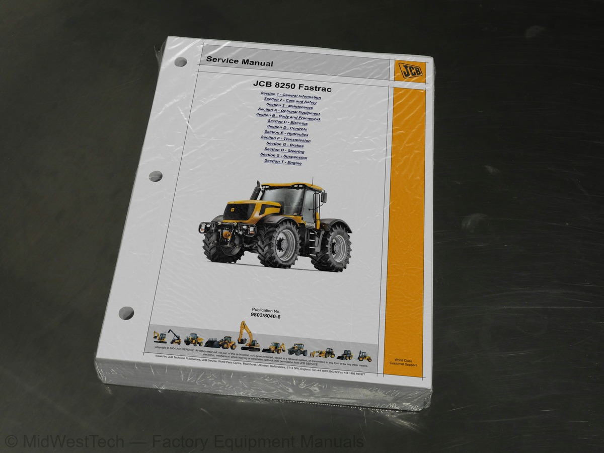
JCB Fastrac 8520 Tractor Service Manual
691 pages · Publication 9803-8040-2
Added to your cart. View cart
- Models
- Fastrac 8520
- Manual type
- Service Manual
- Pages
- 691
- Publication
- 9803-8040-2
- Condition
- Brand new
What's inside
From the manual's own table of contents: 2 sections, 246 entries. See sample pages (PDF, 393 KB)
General63 topics
- Serial Numbers
- Serial Number Plate
- Zinc Plated Fasteners and Dacromet Fasteners
- Introduction
- Zinc Plated Fasteners (golden finish)
- Dacromet Fasteners (mottled silver finish)
- Hydraulic Connections
- O' Ring Face Seal System
- Torque Stop' Hose System
- Sealing and Retaining Compounds
- Safety First
- Safety - Yours and Others
- General Safety
- Operating Safety
- Maintenance Safety
- Service Requirements
- Owner/Operator Support
- Service/Maintenance Agreements
- Initial Service and Inspection (100 Hours)
- Obtaining Replacement Parts
- Health and Safety
- Lubricants
- Battery
- First Aid - Electrolyte
- Service Schedules
- How to Use the Service Schedules
- Service Schedule Tables
- Fluids, Lubricants and Capacities
- Coolant Mixtures
- Cleaning the Machine
- Checking for Damage
- Seats and Seat Belts
- Seats
- Checking the Seat Belt Condition and Security
- Checking the ROPS Structure
- Bonnet
- Opening the Bonnet
- Closing the Bonnet
- Greasing
- General Information
- Propshafts and Rear PTO Drive Shaft
- Front 3-Point Linkage (Optional)
- Front Axle Steering Swivels
- Steering Column Universal Joints
- Rear Suspension Cylinder Pivots
- Hydraulic Lift and 3-Point Linkage
- Pick-up Hitch
- Automatic Trailer Coupling (if fitted)
- Air Conditioning and Heater
- Air Conditioning Filters
- Cleaning the Heater Filter
- Adjusting the Compressor Belt
- Brakes
- Checking the Foot Brake Fluid Level
- Checking the Trailer Air Tank
- Checking and Renewing Foot Brake Pads
- Checking the Park Brake Pads
- Renewing the Park Brake Pads
- Electrical System
- Jump-starting the Engine
- Fuses
- Relay Identification
- Checking the Beam Alignment
Section 3 - Maintenance106 topics
- Engine
- Changing the Air Filter Elements
- Checking the Oil Level
- Changing the Oil and Filter
- Checking the Crankcase Breather Tube
- Cooling System
- Checking the Coolant Level
- Changing the Coolant Filter
- Draining and Refilling the Coolant
- Cleaning the Radiator and Coolers
- Fan Belt
- Fuel System
- Types of Fuel
- Filling the Tank
- Draining the Fuel Filter
- Changing the Fuel Filter Elements
- Hydraulic System
- Checking the Fluid Level
- Changing the Filter Element
- Changing the Hydraulic Fluid and Cleaning the Suction Strainers
- Emptying the Hydraulic Coupling Drain Reservoirs
- Transmission
- Checking the Transmission Oil Level
- Changing the Transmission Oil Filter
- Changing the Transmission Oil and Strainer
- Checking the Clutch Fluid Level
- Axles
- Front Axle
- Rear Axle and PTO
- Tyres and Wheels
- General
- Wheel and Tyre Replacement
- Checking Wheel Nut Torques
- Tyre Inflation
- Checking and Adjusting the Front Wheel Alignment
- Fender Adjustment
- Power Take-off (PTO)
- Front PTO
- Rear PTO
- Windscreen Washer
- Checking Fluid Level
- Automatic Trailer Coupling (Optional)
- Checking for Wear
- Section A - Optional Equipment
- PTO Drive Shaft and Flexible Couplings
- Removal and Replacement
- PTO Gearbox
- Dismantling
- Assembly
- PTO Clutch Dismantling and Assembly
- Air Conditioning
- Service Tools Selection List
- Direct Glazing
- Operation
- Control
- Safety Procedures
- Refrigerant Types
- Hoses and Pipes
- Hoses
- Pipes
- Leak Testing
- Fault Finding
- Component Removal and Replacement
- Components Renewable without Discharging the Refrigerant
- Components Inside Evaporator Unit Casing
- Pressure Switch
- Testing
- Compressor Clutch
- Removal
- Replacement
- Heating System
- Heater Unit
- Using a Multimeter
- Measuring DC Voltage
- Measuring Resistance
- Measuring Continuity
- Measuring Frequency
- Testing a Diode or a Diode Wire
- Maintenance
- Specific Gravity Testing
- Wire and Harness Number Identification
- Wire Numbers and Functions
- Wiring Harness Repair
- Repair Procedure
- Main Components Diagram
- Drawings and Interconnection
- Harnesses
- Description and Programming
- Instruments
- Warnings (Audible/Visual)
- Warnings (Visual only)
- EMS Programming Mode Levels 0 and 1
- Wheel Slip
- Accessing Calibration Menu
- Calibration
- Hand Throttle
- Foot Throttle
- Joystick Centre Position
- Joystick Left/Right Positions
- Transmission Clutch Pedal
- Transmission Range
- Transmission Ratio
- Transmission Turbo Clutch
- Steering Angle
- Accessing the Spool Valve Calibration Mode
- Calibration Mode
Section C - Electrics75 topics
- Accessing the Configuration Mode
- Valve Slices Currently Configured
- Configuring ‘Bosch’ Slices to an 8000 Series Fastrac
- Non-displayable Fault Codes
- Diagnostic Error Codes - ABS
- ABS Code Tables
- Codes Prefixed C to Z
- External Hydraulics
- Control Valve - Electronically Actuated
- Other Hydraulic Circuits
- Introduction to Hydraulic Schematic Symbols
- General (Basic and Functional Symbols)
- Control Valves
- Example of Schematic Circuit
- Complete Machine Circuit without Power Beyond Service
- Component Key
- Complete Machine Circuit with Power Beyond Service
- Electronically Actuated Spool Valve
- Typical Electronically Actuated Spool
- Maximum System Pressure
- Pilot Stand-by Pressure
- Piston Pump (External Hydraulics)
- Control Valve
- Sealing the Driveshaft
- Pump Dismantling and Assembly
- Gear Pump (Suspension and Steering)
- Dismantling and Assembly
- Valve Slices (Green, Blue, Brown, Grey and Front Hitch)
- Pilot Control Valve Slice
- Rear Hitch Slice
- Rear Lift Ram
- Continuously Variable Transmission (CVT)
- Service Tools Section List
- Drive Line Layout
- Main Component Identification
- Actuator Unit
- Hydraulic Circuit
- Valve Block 1
- Valve Block 2
- High Pressure Relief Valve, Forward/Reverse
- Purge Valve
- Operation in Different Modes
- CVT Pressures
- Diferential Lock and PTO Speed Selection
- Forward and Reverse High Pressure Relief Valves
- Master Cylinder
- Filling and Bleeding the System
- Drive Head
- Rear PTO Gearbox
- Brake System
- Tractor ABS System
- Fault Tables
- Brake System Bleeding
- Air Drier/Unloader Valve
- Circuit Protection Valve
- Pressure Modulating Valves
- Non-Return Air Valve
- Trailer Brake Hydraulic Valve
- Pressures and Flow Rates
- Steer Box
- Steering Relief Valve
- Steering Limiters
- Rear Suspension
- Description
- Shock Absorber
- Control Arm
- Panhard Rod
- Coil Spring and Microcellular Spring
- Pressure Testing
- Ride Height
- Discharging Hydraulic Pressure
- Pressure Maintenance Valve
- Suspension Cylinder and Gas Spring
- Anti-roll Bar
- ‘V’ Link
Inside this manual
Real pages from this service manual (691 pages). Open the sample pages (PDF, 392 KB)
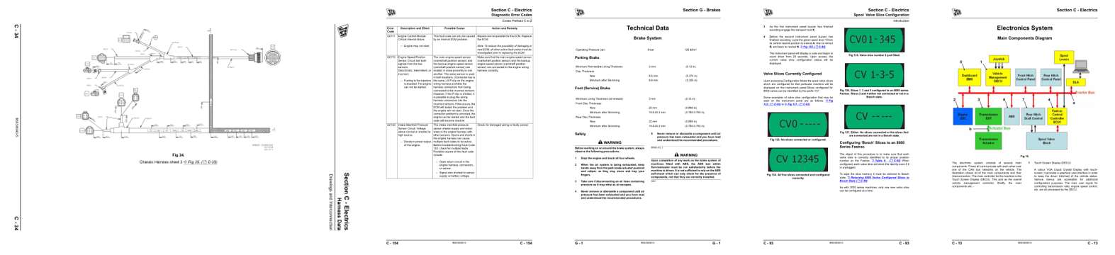
- Diagram, page 210: Harness Data
- Troubleshooting, page 330: Diagnostic Error Codes
- Specifications, page 610: Section G - Brakes
- Color page, page 269: Section C - Electrics
- Color page, page 189: Section C - Electrics
This is a service manual
Here's how it compares to the other manual types.
Service manual
Factory repair procedures and technical information such as specifications, troubleshooting, and wiring and hydraulic diagrams, for the models and systems the manual covers. See What's inside for its topics.
Operator's manual
Safe operation, controls, maintenance schedules, lubrication points, inspections, and basic checks. Repair procedures are in the service manual.
Parts manual
Illustrated diagrams with factory part numbers for identifying components and ordering parts. Repair procedures are in the service manual.
Engine service manuals are sometimes sold separately, since certain machine models were offered with more than one engine option.
What it's used for
Factory manual for in-house farm and construction shop use. Straightforward, complete, and easy to follow. It contains the OEM information dealership service departments and parts counters use to diagnose problems, identify components, and perform maintenance or repairs correctly.
Service shops and owner/operators who repair their own equipment
Identifying correct parts and seeing how assemblies come apart and go back together
Keeping equipment running with less downtime
Factory manual, 691 pages
Quantity one is the manual described above.
Fast free USA shipping
Ships in 1 business day.
60-day returns
Free if the mistake is ours. A manual ordered in error must come back unopened in its shrink-wrap; you pay return shipping and a 20% restocking fee applies. Return policy
Binder not included
Manuals over about 300 pages may need a standard 3-ring binder, which you can buy locally to keep the pages organized for shop use.
Other editions and similar models
Questions about model, serial number, engine coverage or contents? Contact us before purchasing and we'll help confirm it's the right manual. Please verify the manual type, machine model, serial number range and engine coverage before purchasing: manuals ordered in error carry a 20% restocking fee (return policy).