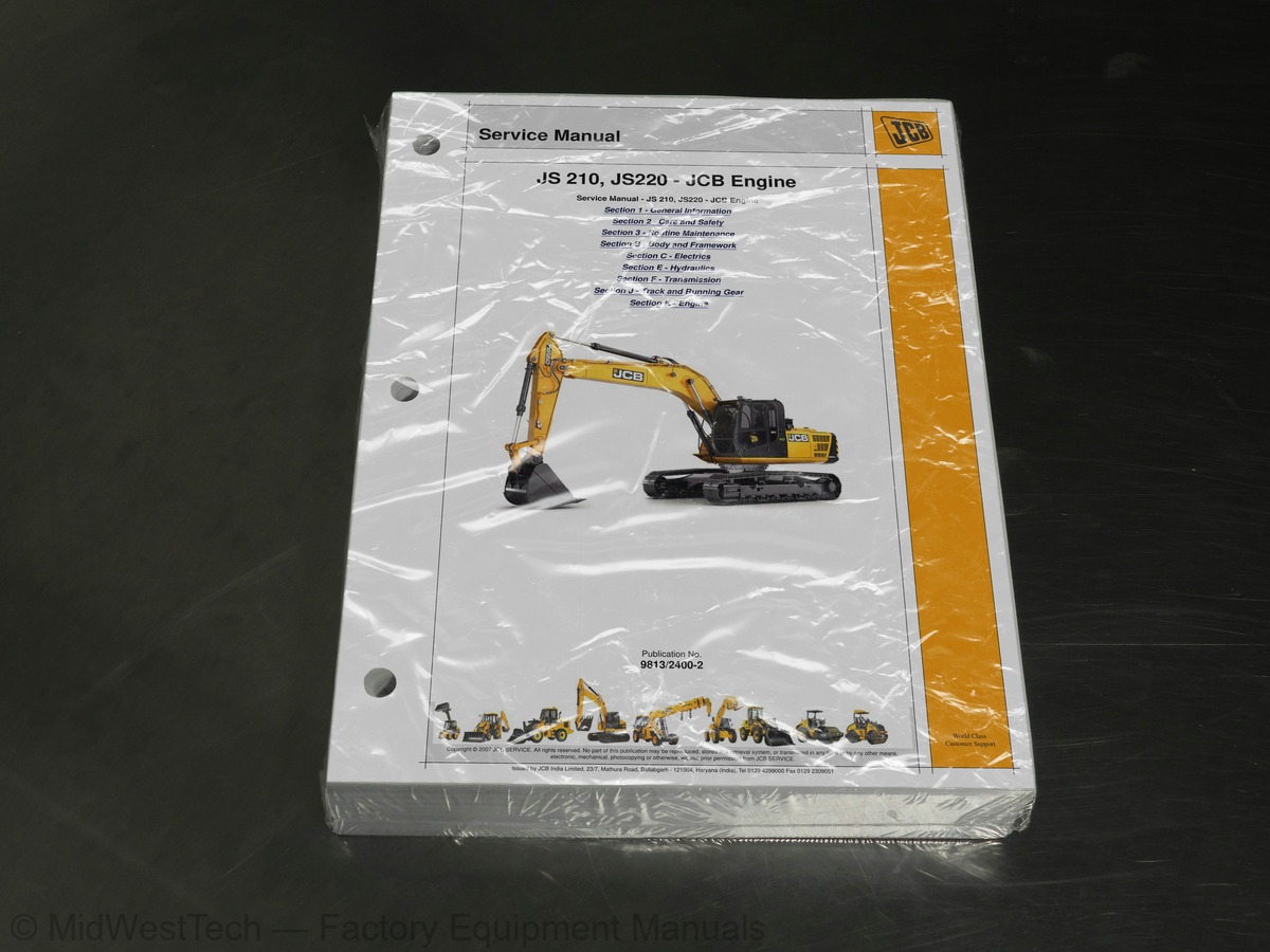
JCB JS 210, JS220 w/JCB Engine Tracked Excavator Service Manual
762 pages · Publication 9813-2400-2
Added to your cart. View cart
- Models
- JS 210, JS220 w/JCB Engine
- Serial coverage
- JS220 from SN 2163177 to 2168079, JS210LC with JCB Dieselmax Engine SN2163079 to 2163161, JS210LC from SN 2163079 to 2168079
- Manual type
- Service Manual
- Pages
- 762
- Publication
- 9813-2400-2
- Condition
- Brand new
What's inside
From the manual's own table of contents: 8 sections, 429 entries. See sample pages (PDF, 407 KB)
Section 1 - General Information28 topics
- About this Manual
- Machine Model and Serial Number
- Using the Service Manual
- Section Numbering
- Left Side, Right Side
- Cross References
- Machine Description
- The JCB Tracked Excavator
- Intended Use
- Component Location
- Identifying Your Machine
- Machine Identification Plate
- Component Identification Plates
- Zinc Plated Fasteners and Dacromet Fasteners
- Introduction
- Bolts and Screws
- Hydraulic Connections
- O' Ring Face Seal System
- Torque Stop' Hose System
- Numerical List
- Tool Detail Reference
- Section B - Body and Framework
- Section C - Electrics
- Section E - Hydraulics
- Section K - Engine
- Sealing and Retaining Compounds
- Colour Coding
- Hydraulic Schematic Colour Codes
Section 2 - Care and Safety8 topics
- Important Information
- The Operator Manual
- Safety Warnings
- Safety Check List
- Safety - Yours and Others
- General Safety
- Operating Safety
- Maintenance Safety
Section 3 - Routine Maintenance85 topics
- Service Requirements
- Owner/Operator Support
- Service/Maintenance Agreements
- Fit for Purpose Tests for Lifting Equipment
- Obtaining Replacement Parts
- Health and Safety
- Lubricants
- Battery
- Service Schedules
- How to Use the Service Schedules
- Calendar Equivalents
- Pre Start Cold Checks, Service Points and Fluid Levels
- Functional Test and Final Inspection
- Service Intervals for Attachments
- Periodic Replacement of Safety Related Components
- Fluids, Lubricants and Capacities
- Engine Lubrication Chart
- Hydraulic Oil Chart
- Typical Lubrication Chart
- Coolant Mixtures
- Fuel
- Tools
- Carrying Tools onto the Machine
- Prepare the Machine for Maintenance
- How to Make the Machine Safe (Excavator Lowered)
- Cleaning the Machine
- Preparing the Machine for Cleaning
- Cleaning the Tracks
- Cleaning the Radiator and Oil Cooler
- Daily Checking
- Greasing
- Slew Ring Bearing
- Slew Ring Teeth and Slew Pinion
- Greasing Points
- Electrical System
- Checking the Battery Electrolyte Level
- Battery Disconnection/Replacement
- Terminal Cleaning
- Jump-Starting the Engine
- Fuses
- Bolt and Nut Torque Specifications
- Engine
- Oil and Filter
- Changing The Coolant
- Checking the Coolant Level
- Changing the Outer Air Filter Element
- Changing the Inner Air Filter Element
- Fan Belt
- Front End Accessory Drive Belt
- Fuel System
- Draining Fuel Tank Impurities
- Draining the Primary Fuel Filter/Sedimenter
- Changing the Primary Fuel Filter/Sedimenter Element
- Draining the Main Fuel Filter/Sedimenter
- Changing the Main Fuel Filter/Sedimenter Element
- Draining the Engine Fuel Filter/Sedimenter
- Changing the Engine Fuel Filter/Sedimenter Element
- Bleeding the System
- Hydraulic System
- Checking the Fluid Level
- Releasing Tank Pressure
- Releasing the Hydraulic Pressure
- Oil and Filters
- Draining Water and Sediment from the Hydraulic Tank
- Air Bleeding Procedures
- Slew Gearbox
- Checking the Slew Gearbox Oil Level
- Changing the Slew Gearbox Oil
- Tracks and Running Gear
- Tracks
- Running Gear
- Bucket
- Checking/Adjusting For Side Play
- Windscreen Washer (If fitted)
- Checking the Level
- Fire Extinguisher (If fitted)
- Troubleshooting
- Engine and Related Area
- Monitor Display - Fault Messages
- Operations
- Hydraulic pump
- Working Attachments
- Travel
- Slew
- Hydraulic ram
Section B - Body and Framework25 topics
- Static Dimensions
- Dig Depth Chart
- JS220 - Monoboom
- JS210 - Monoboom
- Shipping Weight
- Air Conditioning (option)
- Automatic Temperature Control (ATC) System
- Air Conditioning
- Preliminary Checks
- Heater/Air Conditioning Controls (ATC)
- Air Conditioning System Operation
- ATC Control Panel
- Safety Procedures
- HVAC/Air Conditioning Unit
- Removal
- Replacement
- Air Conditioning Compressor
- Removal and Replacement
- Cab Structure
- Direct Glazing
- Checks
- Checking the FOPS Structure
- Cab Panel Removal
- Right Hand Cab Panels
- Left Hand Cab Panels
Section C - Electrics116 topics
- Circuit Symbols
- Inputs and Outputs
- Schematic Diagram
- A.M.S (Advanced Management System)
- Operation
- The AMS System
- Circuit Concepts
- Inputs
- Outputs
- Pulse Width Modulation (PWM)
- ECU 1 Supply to Output Drivers
- Engine Throttle Control
- Engine Throttle Control for Each Mode
- Pump Control for Each Mode
- Hardware Sensing
- Auto Boost Pressure
- Engine Oil Level Warning
- Engine Automatic Warm Up
- Engine Automatic Idle
- Engine One Touch Idle
- Engine Auto Idle and One Touch Idle
- Engine Start/Stop - JS210, JS220
- Engine ECM Feed
- Engine Cranking
- Alternator/No Charge Warning - JS210, JS220
- Limp Mode system
- Lever Lock
- Servo Isolator
- Wiper
- Lower Wiper (option)
- Washer
- Horn
- Travel Alarm
- Soft/Hard (Cushion)
- Slew lock (100% Slew Brake)
- Slew Brake Solenoid Valve Failure
- 3-Speed Travel
- E" Economy, "P" Precision & "A" Auto Modes
- sition and Pump "Q max cut output
- L" Lifting Mode
- Work Lamps
- Viscous Fan
- Fuel Level Sensor/Warning
- Engine Temperature Sensor/Warning
- Coolant Level Warning
- Air Filter Blocked Warning
- Hydraulic Temperature Sensor/Warning
- Quick hitch (option)
- Overload Caution (option)
- Beacon (Option)
- Hammer Only (Option)
- Scrap Magnet (Option)
- Cab Interior Lamp
- Refuelling Pump
- Heated Seat (Option)
- to 12 Volt Converter, Radio and Power Socket
- Service Required Warning
- Cancellation of the Service indicator
- EMS Set Menu
- EMS Set + Mode Menu
- EMS Set+Mode (20 sec) Menu
- Service Off
- Solenoid Override
- Horse Power Control Data Logging Facility
- Throttle Calibration
- JCB Servicemaster
- Using Servicemaster
- Selecting Service Tool Applications
- JS Machine Pages
- System Menus
- HPSetup Overview
- DLA Port Configuration
- Data Link Adaptor
- HPDataLogs
- FLASH Programming Application
- Introduction to the Diagnostics Tool
- Connecting to the Vehicle
- Starting Diagnostic Mode
- Circuit Diagrams
- Indicator Lights (LEDs)
- Stopping Diagnostic Mode
- Language Setting
- Electrical Fault Text Messages Displayed on the EMS
- Changing Machine Components
- Fault Diagnosis (General)
- Permanent Battery Supply (Ignition Off)
- Ignition On
- Ground Tests
- Can - Bus Network Tests
- Harness Tests
- Unit Tests
- Fault Diagnosis ECU-1
- EMS Failure
- Fault Diagnosis - Facia Switch Panel (FSP)
- Testing of ECU Inputs + Outputs
- Testing Low Side Input
- Testing High Side Input
- Testing Low Side Output
- Testing High Side Output
- Using a Multimeter
- Measuring DC Voltage
- Measuring Resistance
- Measuring Continuity
- Measuring Frequency
- Testing a Diode or a Diode Wire
- Maintenance
- Testing
- Specific Gravity Testing
- Wiring Harness Repair
- Repair Procedure
- Fuse Identification
- Harness Interconnection
- Main Harness
- Fascia Link Harness
- Cab Harness JS210 (Includes Engine Harness)
- Cab Roof Harness (JS220)
Section E - Hydraulics143 topics
- General Data
- Main Hydraulic Pump
- Servo Pump
- Proportional Pressure Reducing Valve
- Slew Motor/Gearbox
- Main Control Valve
- Spool Stroke versus Pilot Pressure
- Boom Ram
- Dipper Ram
- Bucket Ram
- Introduction to Hydraulic Schematic Symbols
- General (Basic and Functional Symbols)
- Control Valves
- Example of Schematic Circuit
- Hydraulic Schematics
- Servo Line
- Servo Pressure and Return Line
- Hydraulic Pump Regulation
- Neutral Circuit
- Straight Line Travel
- Travel - Middle Speed
- Boom Up
- Boom Down
- Dipper Out
- Dipper In
- Bucket Opening
- Bucket Close
- Slew Circuit
- Slew over Dipper Priority (A)
- 100% Slew Lock
- Auxiliary Flow
- Hammer
- ISO/SAE Controls
- Motor Operating Principles
- Slew Brake Operation
- Fault Finding
- Motor Does Not Rotate
- Motor Rotates in the Reverse Direction
- Motor Speed is Low
- Motor Brake Working Poorly
- Motor is Driven by Exterior Torque
- Oil Leakage
- Slew Motor Configuration
- Dismantling and Assembly - JS210, JS220
- Dismantling
- Inspection
- Assembly
- Relief Valves
- Dismantling and Assembly
- Function
- Description
- Precautions During Use
- Installation
- Caution During Use
- Maintenance, Inspection Points
- Typical Bucket Ram
- Typical Boom Ram
- Typical Dipper Ram
- Assembling and disassembling procedures
- Cylinder Disassembly
- Cylinder Assembly
- Do’s in a Hydraulic Cylinder
- Dont’s in a Hydraulic Cylinder
- Cushioned Mode - Hand Controller In Neutral
- Cushioned Mode - Hand Controller at Dipper In
- Cushioned Mode - Hand Controller Moved from Dipper In to Neutral
- Cushion Control Off
- Hydraulic Pump Operation
- Main Pumps (P1 and P2)
- Pump Hydraulic Circuit Diagram
- Hydraulic Pump/Regulator Exploded View
- Hydraulic Pump/Regulator Plan View
- Hydraulic Pump Removal and Replacement - JS210, JS220
- Hydraulic Pump Dismantling and Assembly
- Regulator Dismantling and Assembly
- Slew Brake (CT1)
- Isolator (CT2)
- Slew Lock (CT3)
- Maximum flow cut (CT4)
- Stage travel (CT5)
- Boom Priority (CT6)
- Stage relief (CT7)
- Cushion control (CT8)
- Reduction Gear Structure and Working Principles
- Make the Machine Safe
- Pressure Testing - General
- Confirmation of the Oil Temperature
- Warming-up Procedure
- Pressure Testing Points
- Pressure Relief Valve Location
- Main Relief Valve (MRV) Pressure
- Servo Relief Pressure
- Slew Motor Pressure Relief
- Auxiliary Relief Valves
- General
- Option ARV (Monoboom)
- Travel Motor Relief Pressure
- Hydraulic Contamination
- Hydraulic Fluid Quality
- Effects of Contamination
- Cleaning Operation
- Contaminant Standards
- Filters
- Relief Valve
- Slew Motor
- Hydraulic Rams
- Hydraulic Ram Faults and Remedies
- Fault Finding Tests
- Slow or Underpowered
- Harsh Operation When Selecting
- Tracking Off Line
- Poor Tractive Effort
- Loss of Creep Speed
- Loss of High Speed
- Machine Selects High Speed Travel
- Slew Bearing Faults
- Test 001: Testing Negative Control Signal
- Test 002: Test Max Flow Signal
- Test 003: Testing Main Pump Pressure
- Test 004: Testing Horsepower Control
- Test 005: Checking the Operation of the Main Hydraulic Spool
- Test 006: Test the Pressure Switches
- Symptoms of Pressure Switch Failures
- Test 007: Testing Engine Speed Settings
- Pressure Switches vs Engine Speed
- Test 008: Testing Machine Cycle Times
- Bucket Ram Speed
- Dipper Ram Speed
- Boom Ram Speed
- Slew Speed
- Travel Speed
- Travel Linearity
- Test 011: Testing Swing Brake Pressure
- Test 012: Testing Track Motor Relief Valve Settings
- Test 013: Testing Track Motor Drain Line Flow Rate
- Test 014: Loss of High Speed Tracking
- Additional information
- Test 016 - Flow Testing Hydraulic Pumps - Record Sheet
- Test 017: Testing Slew Bearing
- Checking Slew Bearing Backlash
- Checking Slew Bearing Vertical Lift
- Ram Creep Tests - All Services
- Test for Ram Creep
Section F - Transmission15 topics
- Track Motor/Gearbox
- Middle Speed
- Slow Speed Travel (Creep)
- High Speed
- Brake Valve
- Parking Brake
- Rotation Direction
- Precautions During Installation
- Start Up and Running In
- Start Up
- Running In
- Transmission
- Traction Motor
- Counterbalance Valve
- Speed Range Changing
Section J - Track and Running Gear1 topic
- Torque Specifications
Inside this manual
Real pages from this service manual (762 pages). Open the sample pages (PDF, 406 KB)
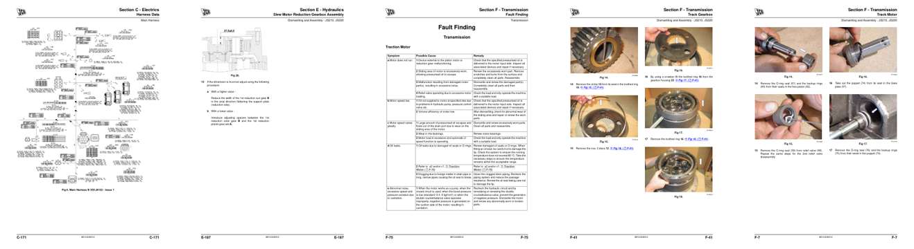
- Diagram, page 363: Harness Data
- Specifications, page 572: Slew Motor Reduction Gearbox Assembly
- Troubleshooting, page 715: Section F - Transmission
- Color page, page 681: Section F - Transmission
- Color page, page 647: Section F - Transmission
This is a service manual
Here's how it compares to the other manual types.
Service manual
Factory repair procedures and technical information such as specifications, troubleshooting, and wiring and hydraulic diagrams, for the models and systems the manual covers. See What's inside for its topics.
Operator's manual
Safe operation, controls, maintenance schedules, lubrication points, inspections, and basic checks. Repair procedures are in the service manual.
Parts manual
Illustrated diagrams with factory part numbers for identifying components and ordering parts. Repair procedures are in the service manual.
Engine service manuals are sometimes sold separately, since certain machine models were offered with more than one engine option.
What it's used for
Factory manual for in-house farm and construction shop use. Straightforward, complete, and easy to follow. It contains the OEM information dealership service departments and parts counters use to diagnose problems, identify components, and perform maintenance or repairs correctly.
Service shops and owner/operators who repair their own equipment
Identifying correct parts and seeing how assemblies come apart and go back together
Keeping equipment running with less downtime
Factory manual, 762 pages
Quantity one is the manual described above.
Fast free USA shipping
Ships in 1 business day.
60-day returns
Free if the mistake is ours. A manual ordered in error must come back unopened in its shrink-wrap; you pay return shipping and a 20% restocking fee applies. Return policy
Binder not included
Manuals over about 300 pages may need a standard 3-ring binder, which you can buy locally to keep the pages organized for shop use.
Other editions and similar models
Questions about model, serial number, engine coverage or contents? Contact us before purchasing and we'll help confirm it's the right manual. Please verify the manual type, machine model, serial number range and engine coverage before purchasing: manuals ordered in error carry a 20% restocking fee (return policy).