JCB JS130, J160 Tracked Excavator Service Manual
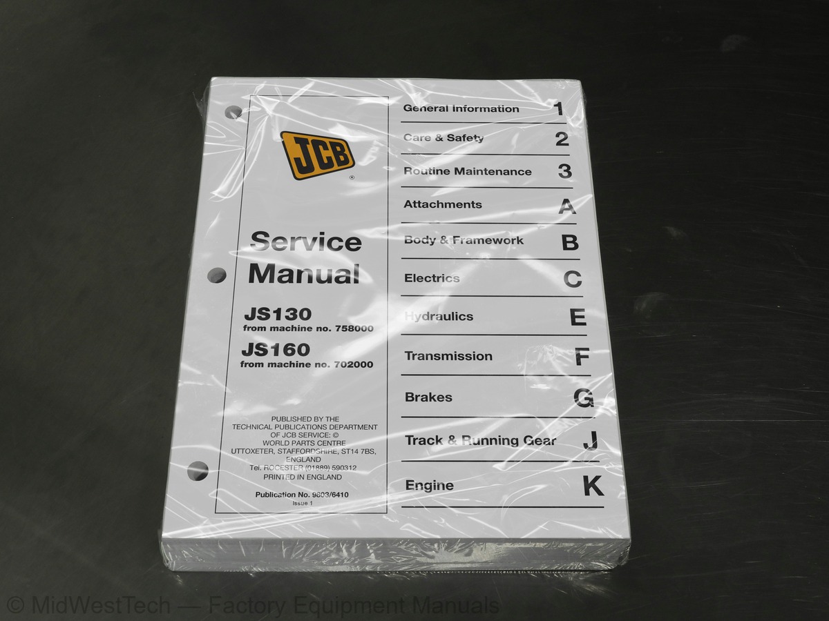
533 pages · Publication 9803-6410
Added to your cart. View cart
- Models
- JS130, J160
- Serial coverage
- JS130 from SN 758000, J160 from SN 702000
- Manual type
- Service Manual
- Pages
- 533
- Publication
- 9803-6410
- Condition
- Brand new
What's inside
From the manual's own table of contents: 193 topics. See sample pages (PDF, 480 KB)
- Bolt and Nut Torque Specifications
- Torque Settings
- Section B - Body and framework
- Section C - Electrics
- Section E - Hydraulics
- Section F - Transmission
- Safety Notices
- General Safety
- Operating Safety
- Maintenance Safety
- Fluids and Lubricants
- Lubricants - Health and Safety
- when using a Breaker or Crusher
- Initial Precautions For New Machine Usage
- Operating Hours Schedule
- Slew Ring Bearing
- Slew Ring Teeth and Slew Pinion
- Excavator End
- Battery
- Air bleeding procedures
- Releasing tank pressure
- Air bleeding from hydraulic pump
- Air bleeding from ram
- Air bleeding from the slew motor
Show all 193 topics
- Checking the fluid level
- Topping up fluid level
- Changing the hydraulic oil
- Changing the Return Filter Element
- Flushing Filters
- Cleaning/Changing the Suction Strainer
- Changing the Air Breather Element
- Draining Tank Impurities
- Changing the Pilot Oil Filter
- Changing the Breaker In-line Filter
- Changing the Drain Line Filter
- Changing the Nephron Filter
- Checking Track Gearbox Oil Level
- Changing the Track Gearbox Oil
- Checking the Slew Gearbox Oil Level
- Changing the Slew Gearbox Oil
- Replenishing Slew Gearbox Grease
- Cleaning the Tracks
- Checking/Adjusting the Track Tension
- Checking the Shoe Plate
- Checking the Rollers and Idler Wheels for Oil Leaks
- Changing the Air Filter Elements
- Checking the Oil Level
- Changing the Oil and Filter(s)
- Checking the Coolant Level
- Coolant Mixtures
- Changing the Coolant
- Adjusting the Fan Belt
- Fitting a New Fan Belt
- Cleaning the Radiator and Oil Cooler
- Draining Fuel Tank Impurities
- Draining the Water Separator
- Changing the Fuel Filter Element
- Bleeding the Fuel System
- Component Location Diagrams
- Performance Evaluation
- Checking the FOPS structure
- Dimensions
- Main Body
- Boom and Slew Frame Installation
- Boom Ram Installation
- Dipper Ram Installation
- Dipper Pivot Installation
- Dipper and Dipper Ram Installation
- Bucket Ram Installation
- Dipper and Dipper Link Installation
- Bucket and Bucket Link Installation
- Bucket Link and Bucket Ram Installation
- Bucket and Dipper Installation
- Shim Adjustment Table
- Operation
- Control
- Safety Procedures
- Fault Finding
- Checking Refrigerant charge Level
- Leak Testing
- Tightening Leaking Hoses
- System Diagnosis
- Torque Specification
- Technical Data
- Battery Testing
- Schematic Diagram
- Operator’s Cab
- Right Console
- Left Console
- Monitor
- Control, Function, Operation
- Basic Operation
- Stepping Motor
- Throttle Related Function
- Stop Motor Function
- Redundancy (back-up) Throttle Control
- Automatic Engine Adjustment
- Idling Control
- Revolution Control for each Mode
- Control of Engine Speed for Breaker Operation
- Engine Auto Warm-up
- Detection of Throttle Motor Assy Defect
- Engine Reverse Rotation Prevention
- Schematic
- Flow Chart
- Boom Lowering Speed Regulation
- Cushioned Boom Starting
- Pressure Increasing System
- Speed Travel and Max Flow Cut
- Soft/Hard Switch
- Power Supply Cut Delay
- Swing Brake/Swing Lock
- Lever Lock
- Travel Warning
- Power Transistor Protection
- Display Monitor
- Throttle Motor and Throttle Link Replacement
- Automatic Adjustment
- Initial Set-up of the Controller for Machine Identification
- Installation
- Self Test
- Fault Diagnosis
- Emergency Engine Stop
- Refuel
- Coolant Refill
- Air Cleaner Clogged
- Low Engine Oil Pressure
- Engine Oil Filter
- Fluid Overheat, water, oil
- Battery Charging
- Electrical System, Message Fault
- Engine Problem
- Sensor Resistance Valve
- Section C
- Technical Data JS130
- Technical Data JS160
- Schematic Hydraulic Circuit JS130
- Shuttle Block
- Pilot Control Line Hose Connection Diagram
- Pressure Measuring Points
- Pressure Relief Valves
- Pressure Testing - General
- Main Relief Valve
- Servo Accumulator
- Pilot Relief Valve
- Slew Motor Relief Valve
- Auxiliary Relief Valves
- Travel Motor Relief Pressure
- Introduction, Specifications
- Schematics
- Dismantling and Assembly
- Introduction, Technical Data
- Precautions During Use
- Spool Location
- Schematic Hydraulic Circuit
- Neutral Circuit
- Removal and Replacement
- Dismantling and Assembly (Sub-assembly Location)
- Introduction, Specification
- Technical Data, Schematics
- Maintenance Specifications
- Introduction
- General Information
- Schematics, Technical Data
- Specifications and Torque Settings
- Bucket Ram Removal and Installation
- Dipper Ram Removal and Installation
- Boom Ram Removal and Installation
- Re-Conditioning
- Removal
- Replacement
- Dismantling
- Assembly
- Hydraulic Motor Components
- Reduction Gear Components
- Hydraulic Circuit
- Specification
- Specifications
- Preparation for Use
- Motor Bleeding
- Testing
- Cross-Sectional View - JS130
- Exploded View (Motor) - JS130
- Exploded View (Gearbox) - JS130
- Component List - JS130
- Cross-Sectional View - JS160
- Exploded View (Motor) - JS160
- Exploded View (Gearbox) - JS160
- Component List - JS160
- Inspection
- Adjustments
- Torque Specifications
- Wear Limits
Inside this manual
Real pages from this service manual (533 pages). Open the sample pages (PDF, 480 KB)
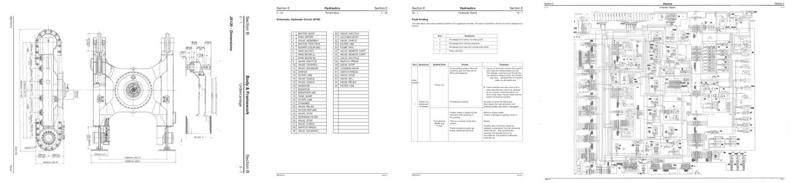
- Specifications, page 80: Section B
- Diagram, page 208: Schematics
- Troubleshooting, page 392: Hydraulic Rams
- Foldout diagram, page 118
This is a service manual
Here's how it compares to the other manual types.
Service manual
Factory repair procedures and technical information such as specifications, troubleshooting, and wiring and hydraulic diagrams, for the models and systems the manual covers. See What's inside for its topics.
Operator's manual
Safe operation, controls, maintenance schedules, lubrication points, inspections, and basic checks. Repair procedures are in the service manual.
Parts manual
Illustrated diagrams with factory part numbers for identifying components and ordering parts. Repair procedures are in the service manual.
Engine service manuals are sometimes sold separately, since certain machine models were offered with more than one engine option.
What it's used for
Factory manual for in-house farm and construction shop use. Straightforward, complete, and easy to follow. It contains the OEM information dealership service departments and parts counters use to diagnose problems, identify components, and perform maintenance or repairs correctly.
Service shops and owner/operators who repair their own equipment
Identifying correct parts and seeing how assemblies come apart and go back together
Keeping equipment running with less downtime
Factory manual, 533 pages
Quantity one is the manual described above.
Fast free USA shipping
Ships in 1 business day.
60-day returns
Free if the mistake is ours. A manual ordered in error must come back unopened in its shrink-wrap; you pay return shipping and a 20% restocking fee applies. Return policy
Binder not included
Manuals over about 300 pages may need a standard 3-ring binder, which you can buy locally to keep the pages organized for shop use.
Other editions and similar models
Questions about model, serial number, engine coverage or contents? Contact us before purchasing and we'll help confirm it's the right manual. Please verify the manual type, machine model, serial number range and engine coverage before purchasing: manuals ordered in error carry a 20% restocking fee (return policy).