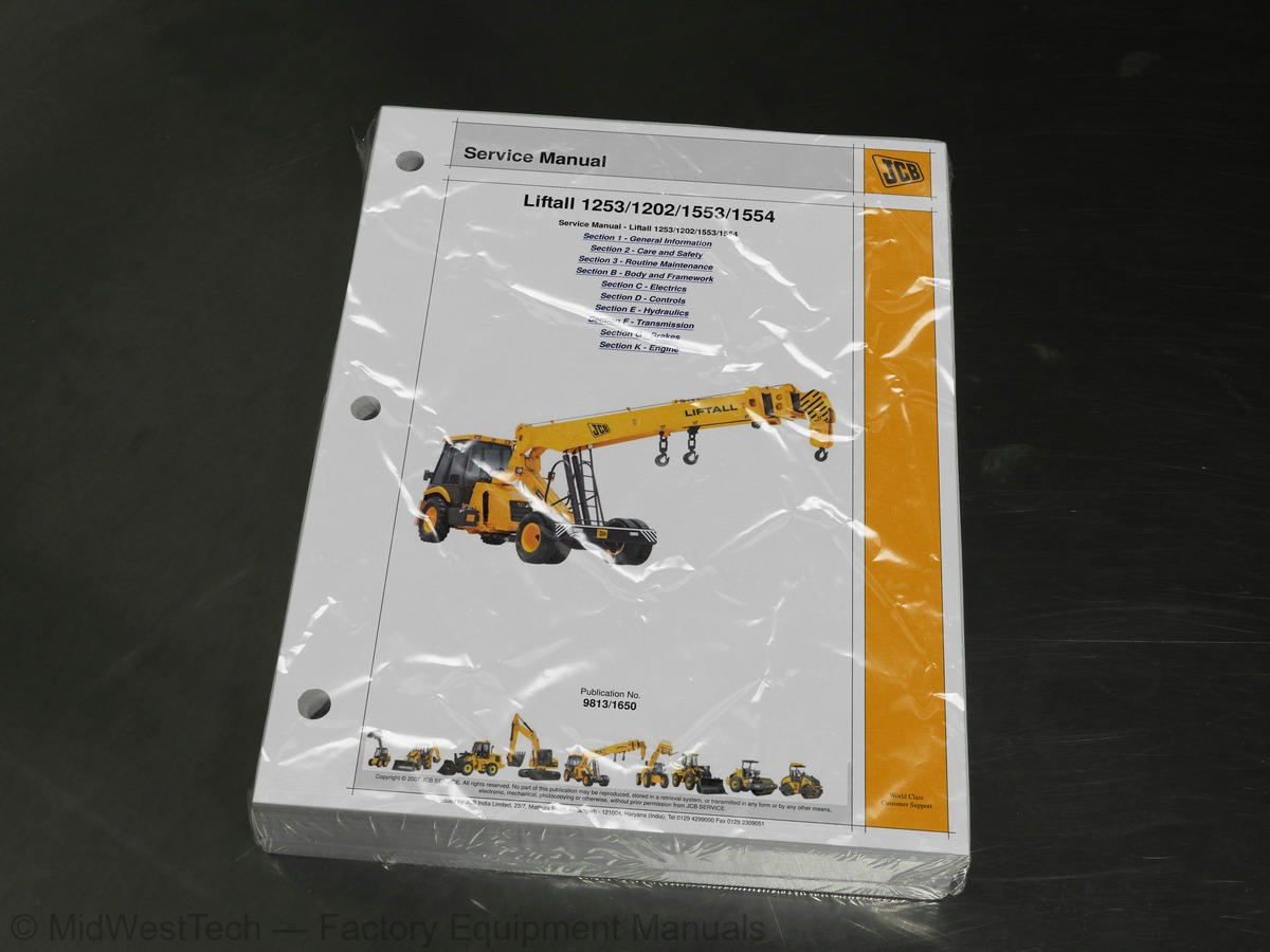
JCB Liftall 1253, 1202, 1553, 1554 Crane Service Manual
505 pages · Publication 9813-1650
Added to your cart. View cart
- Models
- Liftall 1253, 1202, 1553, 1554
- Manual type
- Service Manual
- Pages
- 505
- Publication
- 9813-1650
- Condition
- Brand new
What's inside
From the manual's own table of contents: 5 sections, 219 entries. See sample pages (PDF, 395 KB)
General15 topics
- Machine Identification
- Machine Identification Plate
- Load Chart
- Torque
- Torque Settings
- Tightening Torque Values for Metric Hardware
- Tightening Torque Values for Hydraulic Hoses
- Tightening Torque Values for Hydraulic Adaptor
- Service Tools
- Numerical List
- Tool Detail Reference
- Section B - Body and Framework
- Section C - Electrics
- Section E - Hydraulics
- Section K - Engine
Section 3 - Routine Maintenance56 topics
- Service Requirements
- Introduction
- Owner/Operator Support
- Service/Maintenance Agreements
- Initial Service and Inspection
- Fit for Purpose Tests for Lifting Equipment
- Obtaining Replacement Parts
- Health and Safety
- Lubricants
- Battery
- Service Schedule
- How to Use the Service Schedules
- Calendar Equivalents
- Pre-Start Cold Checks, Service Points and Fluid Levels
- Fluids, Lubricants and Capacities
- Fuels
- Prepare the Machine for Maintenance
- How to Make the Machine Safe
- Cleaning the Machine
- Preparing the Machine for Cleaning
- Checking For Damage
- Check the Machine Body and Structure
- Check the Tyres
- Check the Seat and Seat Belt
- Check the Hydraulic Hoses and Fittings
- Check the Electrical Circuits
- Checking The ROPS/FOPS Structure
- Checking Hooks, Shackles and Chains
- Greasing
- Greasing Points
- Oiling
- Park Brake Clevis
- Clutch Pedal Linkage
- Brakes
- Checking the Brake Fluid Level
- Electrical System
- Jump Starting the Engine
- Fuses
- Engine
- Oil and Filter
- Cooling System
- Adjusting the Fan Belt
- Air Intake System
- Fuel System
- Draining Fuel Tank Impurities
- Hydraulic System
- Checking the Fluid Level
- Hydraulic Tank Cap/Breather
- Changing the Return Line Filter Element
- Changing the Suction Strainer
- Transmission
- Gearbox
- Wheels and Tyres
- Water Ballast
- Tyre Inflation
- Wheel Nuts
Section B - Body and Framework29 topics
- Welding
- Boom Assembly Overview
- General Components
- Boom Assembly Service Procedure (Liftall 1253)
- General Instructions
- Sub-assembly
- Liftall 1253
- Boom Members all Around Clearance Settings – Liftall 1253
- Boom Assembly Service Procedure (Liftall 1202)
- Liftall 1202
- Boom Members All Around Clearance Settings – Liftall 1202
- Standard Wear Pads Assembly – Liftall 1553
- Boom Members All Around Clearance Settings (Liftall 1553)
- Boom Assembly Service Procedure (Liftall 1554)
- Standard Wear Pads Assembly – Liftall 1554
- Boom Members all Around Clearance Settings (Liftall 1554)
- Wire Rope Overview
- Rope Construction
- Service Instructions
- Wire Rope Replacement/Serviceability Procedure
- Overload Spring Assembly/Disassembly
- Overload Spring Assembly/Disassembly Procedure
- Overload Spring Assembly and Bearing Change Procedure
- Load Moment Indicator (LMI) (Optional)
- Basic Introduction
- Features and Benefits
- Working Principle
- LMI Installation
- Troubleshooting and Fault Diagnosis
Section C - Electrics20 topics
- Using a Multimeter
- FLUKE 85 Multimeter
- Measuring DC Voltage
- Measuring Resistance
- Measuring Continuity
- How to Test a Diode or a Diode Wire
- Maintenance
- First Aid - Electrolyte
- Activating New Battery
- Alternator
- General Description
- Service Precautions
- Charging Circuit Test
- Starter Motor
- Starting Circuit Test
- Schematic Diagram
- Fuse Box Decal
- Electrical Circuit
- Electrical Harness
- Wiring Harness Cut-in Information
Section D - Controls52 topics
- Operating levers
- Hand Operated RH Side Controls
- Left Hand Controls
- Foot Operated Controls
- Control Levers, Rod Linkages and Knob
- Dismantling and Assembly
- Clutch Pedal Linkage and Free Play Adjustments
- Reasons for Clutch Adjustment
- Basic Circuit
- Component Location
- Introduction to Hydraulic Schematic Symbols
- General (Basic and Functional Symbols)
- Control Valves
- Example of Schematic Circuit
- Circuit Schematics
- Hydraulic Pump
- Hydraulic Pump Operation
- Pump Cartridge Assembly
- Hydraulic Winch (Liftall 1253 & Liftall 1202)
- Hydraulic Winch
- Hydro Motor (Radial Piston Type)
- Features of Crankshaft Design Radial Piston Hydraulic Motors
- Operating the Winch
- Installation
- Winch Overhauling
- Disassembly of Gear Drive Unit and Brake Unit
- Assembly of Gear Drive Unit and Brake Unit
- Winch Bracket, Drum and Drive Unit Assembly
- Preventive Maintenance
- Hydraulic Winch (Liftall 1553 & Liftall 1554)
- Technical Data
- Technical Information
- General Safety Instructions
- Start-up Information
- Handling and Installation
- Maintenance Information
- Assembly Procedure
- Assembly and Disassembly of Brakes
- Maintenance Schedule
- Problems and Solutions
- General Information
- Stopping and Parking the Machine
- Double Acting Rams
- Steering Ram
- Lift Ram
- Extension Ram
- Assembly and Disassembly
- Dismantling of Hydraulic Cylinder
- Replacement of Gland/Rod Seal
- Replacement of Piston Seal
- Valve Description
- Description
Section E - Hydraulics42 topics
- Assembly and Testing
- Assembly
- Testing
- Flow and Pressure Controlled Valve
- Dismantling and Re-installing
- Procedure
- Fault Finding
- Service Procedure
- Hydraulic Fluid Quality
- Filters
- Lack of power in all hydraulic functions
- All hydraulics rams slow to operate
- operate
- load
- A spool is sticking
- Leaking oil seal (Control valve)
- Ram Creep
- Hydraulic oil becomes too hot
- diagrams (near the beginning of the Hydraulics Section)
- information at the beginning of this manual
- component
- hydraulic fluid. Drain and replace if necessary
- to the hydraulics
- elsewhere in the circuit
- Transmission Installation Information (as supplied with Liftall)
- Gear Box
- Check List and Troubleshooting
- Check List
- Troubleshooting
- Differential
- Rear End
- Important Instructions
- Clutch Release Finger Setting Procedure
- Working Principal
- Basic System Operation
- Front Brake Adjustment Procedure
- Checking the Wheel Cylinder, Brake Shoe Liners Conditions
- Rear Brakes Adjustment Procedure
- Brake System Aggregates Service and Repairs Information
- Removal and Replacement
- Removal
- Re-assembling the engine
Inside this manual
Real pages from this service manual (505 pages). Open the sample pages (PDF, 394 KB)
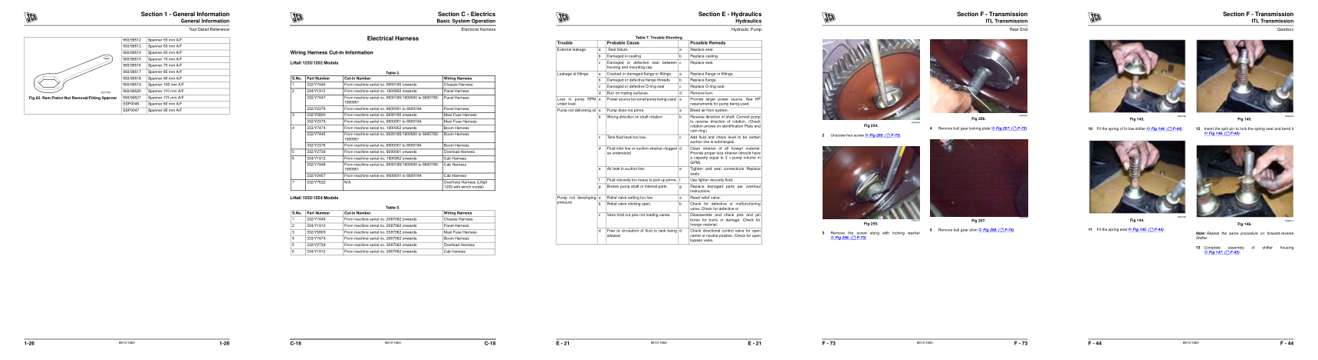
- Specifications, page 30: Section 1 - General Information
- Diagram, page 205: Section C - Electrics
- Troubleshooting, page 254: Hydraulics
- Color page, page 420: Section F - Transmission
- Color page, page 391: Section F - Transmission
This is a service manual
Here's how it compares to the other manual types.
Service manual
Factory repair procedures and technical information such as specifications, troubleshooting, and wiring and hydraulic diagrams, for the models and systems the manual covers. See What's inside for its topics.
Operator's manual
Safe operation, controls, maintenance schedules, lubrication points, inspections, and basic checks. Repair procedures are in the service manual.
Parts manual
Illustrated diagrams with factory part numbers for identifying components and ordering parts. Repair procedures are in the service manual.
Engine service manuals are sometimes sold separately, since certain machine models were offered with more than one engine option.
What it's used for
Factory manual for in-house farm and construction shop use. Straightforward, complete, and easy to follow. It contains the OEM information dealership service departments and parts counters use to diagnose problems, identify components, and perform maintenance or repairs correctly.
Service shops and owner/operators who repair their own equipment
Identifying correct parts and seeing how assemblies come apart and go back together
Keeping equipment running with less downtime
Factory manual, 505 pages
Quantity one is the manual described above.
Fast free USA shipping
Ships in 1 business day.
60-day returns
Free if the mistake is ours. A manual ordered in error must come back unopened in its shrink-wrap; you pay return shipping and a 20% restocking fee applies. Return policy
Binder not included
Manuals over about 300 pages may need a standard 3-ring binder, which you can buy locally to keep the pages organized for shop use.
Questions about model, serial number, engine coverage or contents? Contact us before purchasing and we'll help confirm it's the right manual. Please verify the manual type, machine model, serial number range and engine coverage before purchasing: manuals ordered in error carry a 20% restocking fee (return policy).