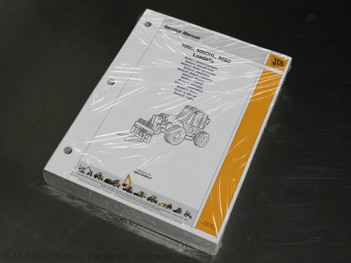
JCB Loadall 506C, 506CHL, 508C Telehandler Service Manual
717 pages · Publication 9803-3640U
Added to your cart. View cart
- Models
- Loadall 506C, 506CHL, 508C
- Serial coverage
- 506C from SN 579781, 506CHL from SN 579569, 508C from SN 579569
- Manual type
- Service Manual
- Pages
- 717
- Publication
- 9803-3640U
- Condition
- Brand new
What's inside
From the manual's own table of contents: 2 sections, 219 entries. See sample pages (PDF, 338 KB)
General85 topics
- About This Manual
- Machine Model and Serial Number
- Using the Service Manual
- Units of Measurement
- Section Numbering
- Left Side, Right Side
- Using the Machine
- Cab/Canopy
- Cross References
- Identifying Your Machine
- Machine Identification Plate
- Component Identification Plates
- Zinc Plated Fasteners and Dacromet Fasteners
- Introduction
- Bolts and Screws
- Hydraulic Connections
- O' Ring Face Seal System
- Torque Stop' Hose System
- Numerical List
- Tool Detail Reference
- Section B - Frame and Bodywork
- Section C - Electrics
- Section E - Hydraulics
- Section F - Transmission
- Section H - Steering
- Section K - Engine
- Sealing and Retaining Compounds
- Colour Coding
- Hydraulic Schematic Colour Codes
- Important Information
- The Operator Manual
- Safety Warnings
- Safety Check List
- Safety - Yours and Others
- General Safety
- Operating Safety
- Maintenance Safety
- Safety Decals
- Safety Decal Definitions
- Service Requirements
- Owner/Operator Support
- Service/Maintenance Agreements
- Initial Service and Inspection (100 Hours)
- Obtaining Replacement Parts
- Health and Safety
- Lubricants
- Battery
- First Aid - Electrolyte
- Service Schedules
- How to Use the Service Schedules
- Machines with A and R Series Engines
- Machines with JCB Dieselmax Engine
- Fluids, Lubricants and Capacities
- Coolant Mixtures
- Greasing
- Every 50 Hours
- Every 500 Hours
- Every 1000 Hours
- Oiling
- Park Brake Cable
- Control Levers
- Boom Chains
- Cleaning the Machine
- Preparing the Machine for Cleaning
- Checking for Damage
- Seat Belt
- Checking the Seat Belt Condition and Security
- ROPS/FOPS Structure
- Checking the ROPS/FOPS Structure
- Boom Safety Strut
- Installing
- Removing
- Access Panels
- Radiator Grill
- Battery Cover
- Engine Hood and Cover
- Brakes
- Park Brake Adjustment (Later Machines)
- Checking the Foot Brake Fluid Level
- Electrical System
- Jump Starting the Engine
- Adjusting the Alternator Drive Belt
- Engine Air Filter
- Cleaning the Pre-Cleaner (if fitted)
- Changing the Elements
Section 3 - Routine Maintenance62 topics
- Engine (A and R Series)
- Checking the Oil Level
- Changing the Oil and Filter
- Checking the Coolant Level
- Changing the Coolant
- Engine (JCB Dieselmax)
- Front End Accessory Drive Belt
- Fuel System
- Types of Fuel
- Filling the Tank
- Machines with A Series Engine
- Machines with R Series Engine
- Hydraulic System
- Checking the Fluid Level
- Hydraulic Tank Cap
- Changing the Filter Element
- Checking the Hose Burst Protection Valves
- Transmission
- Checking the Transmission Oil Level
- Changing the Transmission Oil and Filter
- Tires and Wheels
- Tire Inflation
- Checking the Wheel Nut Torques
- Tire Ballast
- Axles
- Front and Rear Axle
- Windshield Washer
- Checking the Level
- Rivet Nuts
- Slide Hammer Kit
- Removal and Replacement
- Boom Shimming
- Servicing
- Removal, Inspection and Replacement
- Glazing
- General Electrical Data
- Fuses and Relays
- Circuit Schematics
- Using a Multimeter
- Alternator
- Starter Motor
- Wire and Harness Number Identification
- Wiring Harness Repair
- Dismantling and Assembly
- Dismantle and Assembly
- Dismantling, Inspection and Assembly
- Proximity Switches (if fitted)
- Drawings And Interconnection
- 506C Machines
- 506CHL and 508C Machines
- General Description
- Introduction to Hydraulic Schematic Symbols
- Hydraulic Pump
- Hose Burst Check Protection
- Parallel Lift
- General Machine
- Hydraulic Contamination
- Connecting/Disconnecting Hydraulic Hoses
- Venting Hydraulic Pressure
- Testing and Adjustment
- Precautions During Use
- Bleed Procedures
Section F70 topics
- Syncro Shuttle
- Powershift
- Axles
- Tyres
- Recovery Procedure
- General Description - Syncro Shuttle
- General Description - Powershift
- Powershift, Drive Paths
- Syncro Shuttle
- Powershift
- Syncro Shuttle
- Powershift
- Torque Converter
- Testing
- Dismantling
- Assembly
- Dismantling
- Assembly
- Solenoid Valve - Dismantling and Assembly
- PTFE Piston Ring Seals - Fitting Procedure
- Collapsible Spacer - Assembly
- Output Shaft Removal - Larger Diameter Gear
- Summary of Changes
- PS700 Section Views and Torque Figures
- PS750 Section Views and Torque Figures
- Dismantling (With Reverser Shaft Cover Plate)
- Assembling (With Reverser Shaft Cover Plate)
- List of Components
- Dismantling (With Reverser Shaft Sealing Plug & PS750)
- Assembly (With Reverser Shaft Sealing Plug & PS750)
- Location of Components
- Dismantling
- Assembly
- Solenoid Identification
- Torque Converter Stall Test
- Clutch Leakage Testing
- Pressure & Flow Testing
- Propshafts - Removal and Replacement
- Road Wheel - Removal and Replacement
- Water Ballast Tires
- Front Axle
- Rear Axle
- Pinion Depth
- Renewing the Pinion Oil Seal
- Oil Contamination
- Flushing System
- Checking Transmission Oil Level
- Axle Operating Temperature
- Section F
- Oil Seal Replacement
- Wear Sleeve Fitting
- Axle and Gearbox Driveshaft Flange Seals
- Hub and Driveshaft - Fitting Bearing Carrier Seal
- Axles (SD55)
- All Models
- Brake Piston Seal Leakage
- Testing
- Bleeding Procedure
- Removal
- Replacement
- Machines up to SN 586873
- Renewing the Brake Pads
- Machines from SN 586874
- Brake Calliper
- Hydraulic Steer Circuit
- Steer Unit Operation
- Priority Valve Operation
- Steer Mode Valve Operation
- Bleeding
- Re-phasing the Road Wheels
Inside this manual
Real pages from this service manual (717 pages). Open the sample pages (PDF, 337 KB)
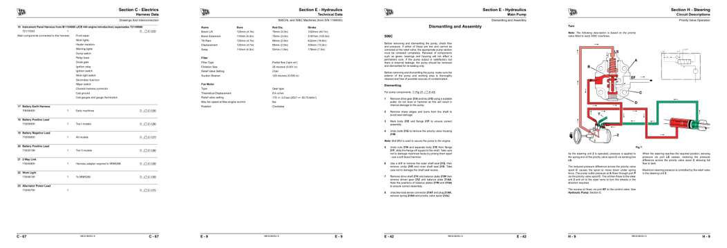
- Diagram, page 262: Harness Data
- Specifications, page 372: Section E - Hydraulics
- Repair procedure, page 405: Section E - Hydraulics
- Color page: Section H - Steering
This is a service manual
Here's how it compares to the other manual types.
Service manual
Factory repair procedures and technical information such as specifications, troubleshooting, and wiring and hydraulic diagrams, for the models and systems the manual covers. See What's inside for its topics.
Operator's manual
Safe operation, controls, maintenance schedules, lubrication points, inspections, and basic checks. Repair procedures are in the service manual.
Parts manual
Illustrated diagrams with factory part numbers for identifying components and ordering parts. Repair procedures are in the service manual.
Engine service manuals are sometimes sold separately, since certain machine models were offered with more than one engine option.
What it's used for
Factory manual for in-house farm and construction shop use. Straightforward, complete, and easy to follow. It contains the OEM information dealership service departments and parts counters use to diagnose problems, identify components, and perform maintenance or repairs correctly.
Service shops and owner/operators who repair their own equipment
Identifying correct parts and seeing how assemblies come apart and go back together
Keeping equipment running with less downtime
Factory manual, 717 pages
Quantity one is the manual described above.
Fast free USA shipping
Ships in 1 business day.
60-day returns
Free if the mistake is ours. A manual ordered in error must come back unopened in its shrink-wrap; you pay return shipping and a 20% restocking fee applies. Return policy
Binder not included
Manuals over about 300 pages may need a standard 3-ring binder, which you can buy locally to keep the pages organized for shop use.
Questions about model, serial number, engine coverage or contents? Contact us before purchasing and we'll help confirm it's the right manual. Please verify the manual type, machine model, serial number range and engine coverage before purchasing: manuals ordered in error carry a 20% restocking fee (return policy).