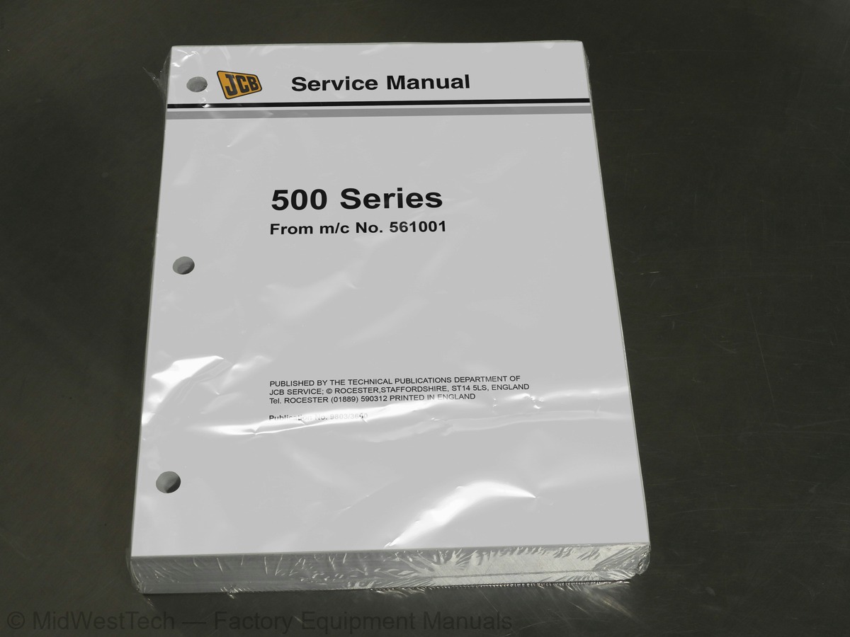
JCB Loadall 525-58, 525-67, 530-95, 530-110, 530-120, 530-67, 535-67, 537-130 Telescopic Handler Service Manual
736 pages · Publication 9803-3600
Added to your cart. View cart
- Models
- Loadall 525-58, 525-67, 530-95, 530-110, 530-120, 530-67, 535-67, 537-130
- Serial coverage
- 525-58 and 525-58 Farm Special - from machine Serial Number 561001, 525-67 and 525-67 Farm Special - from machine Serial Number 561001, 525-58 and 525-67 Farm Special Plus, 525-58 and 525-67 Basic Servo Options, 527-58 and 527-67 - from machine Serial Number 572775, 530-95 - from machine Serial Number 564980, 530-110 - from machine Serial Number 563359, 530-110 and 530-120 - PlaceAce, 530-110 and 530-120 Servo Options, 530-120 - from machine Serial Number 562601, 530-67 and 530-67 Farm Special - from machine Serial Number 571001, 535-67 - from machine Serial Number 572775, 537-120 and 537-130 from machine Serial Number 572900
- Manual type
- Service Manual
- Pages
- 736
- Publication
- 9803-3600
- Condition
- Brand new
What's inside
From the manual's own table of contents: 11 sections, 218 entries. See sample pages (PDF, 424 KB)
General19 topics
- General
- Hydraulics
- Body and Framework
- Engine
- Transmission
- Axles
- Brakes
- Hydraulic Steering
- Electrics
- Service Tools
- precautions when working on them
- Wear a face mask and gloves
- Work in a well ventilated area and do not smoke
- Do not use a rotary wire brush, use a hand scraper
- water to contain loose particles
- heavy duty gloves and special safety glasses are worn
- place material into plastic bags
- use wire wool to remove burnt remains
- water
General9 topics
- Torque Settings
- Identifing Your Machine
- Service Schedules
- Front Axle
- Rear Axle
- Carriage Lock Pins
- Boom Wear Pad Runways
- Oiling
- Boom Safety Strut
Hydraulics35 topics
- General Description
- Draining Fluid & Cleaning Suction Strainers
- Pump Operation
- Removal & Replacement
- Dismantle & Assembly
- Machine Neutral Circuit (without torsion box cooling)
- Control Valve Block Neutral Circuit
- Hose Burst Operation
- Sway Operation
- Stabiliser Check Valve Operation
- Stabiliser Operation
- M.R.V. Operation
- A.R.V. Operation
- Control Valve Block Removal & Replacement
- Control Valve Block Dismantle & Assembly
- Dual Function Controls Assembly
- Pressure Testing
- Lift Rams Removal & Replacement
- Displacement Rams Removal & Replacement
- Extension Ram Removal & Replacement (525-58, 527-58)
- Tilt Ram Removal & Replacement
- Sway Ram Removal & Replacement
- Tow Hitch Ram Removal & Replacement
- Boom Hoses Removal & Replacement (530-95)
- Removal & Replacement (530-95)
- Extension Ram Removal & Replacement (530-95)
- Stabiliser Ram Removal & Replacement
- Diverter Valve Removal & Replacement
- Diverter Valve Dismantle & Assembly
- Typical Ram Dismantle & Assembly
- Tow Hitch Ram Dismantle & Assembly
- Typical Ram with Dowel Head Dismantle & Assembly
- Fan Motor Removal, Replacement & Adjustment
- Fan Motor (Sundstrand) Dismantle & Assembly
- Fan Motor (Ultra) Dismantle & Assembly
Body and Framework24 topics
- Boom Shimming - Typical Method
- Cab Removal & Replacement
- Front Windscreen Removal & Replacement
- Rear Window Removal & Replacement
- Side Window Removal & Replacement
- Rear Window Hinged
- Q - Fit Carriage Removal & Replacement
- Technical Data
- Description of Operation
- Control
- Safety Procedures
- Wiring Diagram
- Fault Finding
- Leak Testing
- Condenser Coil Cleaning
- Condenser Fan Relay - Removal and Replacement
- Receiver-Drier - Removal and Replacement
- Binary Switch - Removal and Replacement
- Evaporator Unit - Removal and Replacement
- Thermostat - Removal and Replacement
- Blower Motor - Removal and Replacement
- Expansion Valve - Removal and Replacement
- Evaporator Coil - Removal and Replacement
- Adjusting the Compressor Drive Belt
Loadall PlaceAce Control System23 topics
- Control System Description
- Valve Block Operation
- Pulsar Description & Operation
- Valve Block Removal & Replacement
- Pulsar Solenoid Removal & Replacement
- Main Spool Removal & Replacement
- Boom Angle Sensor Removal & Replacement
- Boom Extension Sensor Removal & Replacement
- Attitude Sensor Removal & Replacement
- Motion Pac Control Unit Removal & Replacement
- Driver Cards Removal & Replacement
- Display Unit Removal & Replacement
- Joystick Removal & Replacement
- Lever Control (Stabilisers) Removal & Replacement
- Control Valve Dismantle & Assembly
- Valve Stack Dismantle & Assembly
- Full System Calibration
- Vehicle Attitude & Tachometer Signal Calibration
- Pulsar Solenoid Calibration
- Driver Card Calibration/Adjustment
- Functional Checks
- Schematic Hydraulic Circuit 530-110/120
- Schematic Electrical Circuit 530-110/120
Servo and Basic Servo Control System7 topics
- Valve Block Main Spool Operation
- Joystick Control Lever Operation
- Control Valve Section Dismantle & Assembly
- Control Valve Inlet & Outlet Dismantle & Assembly
- Lever Control Removal & Replacement
- Bench Testing Joystick Control Levers
- Bench Testing Sway/Stabiliser Control Levers
Engine14 topics
- Engine Cover
- Engine Oil Filter
- Fuel Filter
- Fuel Pump
- Bleeding
- Cooling System
- Alternator Drive Belt
- Pre-Cleaner
- Air Filter
- Radiator
- Engine Removal & Replacement
- Exhauster Removal & Replacement
- Turbo Charger Engine Insulation
- Naturally Aspirated Engine Insulation
Axles20 topics
- Road Wheel Removal & Replacement
- Front Axle Breather Removal & Replacement
- Axle Oil Level
- Cutaway of Front Axle
- Cutaway of Rear Axle
- Removal, Replacement & Proximity Switch Setting
- Hub (Dowel) & Driveshaft Dismantling
- Hub (Dowel) & Driveshaft Assembly
- Front Hub (Splined) & Driveshaft Dismantling
- Front Hub (Splined) & Driveshaft Assembly
- Rear Hub (Splined), Brakes & Driveshaft Dismantling
- Rear Hub (Splined), Brakes & Driveshaft Assembly
- Brakes Dismantling
- Brakes Assembly
- Front Drive Head Dismantling
- Front Drive Head Assembly
- Renewing Axle Pinion Oil Seal
- Rear Drive Head Dismantling
- Rear Drive Head Assembly
- Limited Slip Differential Dismantle & Assembly
Brakes16 topics
- Parking Brake Adjusting & Testing
- Parking Brake Dismantling & Assembly
- Lever Adjustment
- Cable Adjustment
- Removal
- Pad Removal
- Inspection
- Replacement
- Dismantling
- Inspection
- Assembling
- Torque Figures
- Brake System Bleeding (Front Axle)
- Brake System Bleeding (Rear Axle)
- Removal & Replacement
- Dismantling & Assembly
Hydraulic Steering19 topics
- Flow Regulating Valve Operation
- Tandem Steering/Fan Pump Dismantling & Assembly
- Steering/Fan Pump Removal & Replacement
- Single Steering/Fan Pump Dismantling & Assembly
- Wheel Steer
- Crab
- Wheel Steer
- Crab
- Operation 1
- Operation 2
- Normal Operation
- Shock Operation
- Priority Valve Description
- Steering Unit Removal & Replacement
- Steering Unit Dismantling & Assembly
- (Machines Without IP67 Electrics)
- (Machines With IP67 Electrics)
- Steering Ram Removal & Replacement
- Typical Steer Ram with Dowel Piston Head
Electrics18 topics
- Introduction
- Fuses
- Relay Location
- Test Methods
- Batteries Testing
- Precautions
- Testing
- Removal & Replacement
- Dismantling & Assembly
- Starting Circuit Test
- Removal & Replacement
- Dismantling & Assembly
- Safe Load Indicator Adjustment
- Safe Load Indicator Testing from serial No. 576404
- Harness Repair
- Machines without IP67 Electrics (With Road Lights)
- Wire Number Identification
- Powershift Circuit
Service Tools3 topics
- Numerical List
- Section List
- Sealing and Retaining Compounds
Inside this manual
Real pages from this service manual (736 pages). Open the sample pages (PDF, 424 KB)
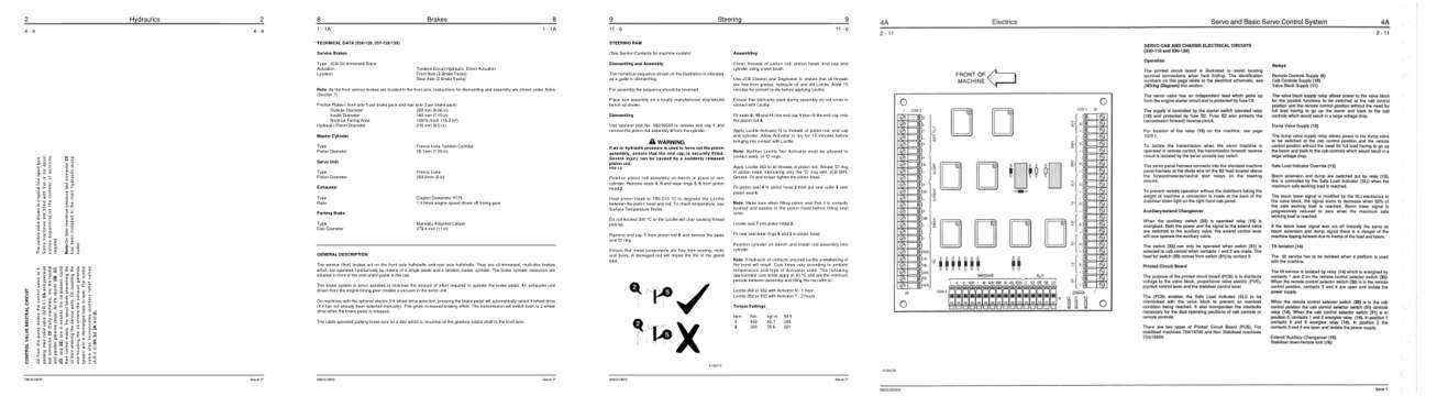
- Diagram, page 76: Hydraulics
- Specifications, page 582: Brakes
- Repair procedure, page 659: STEERING RAM
- Foldout diagram, page 309
This is a service manual
Here's how it compares to the other manual types.
Service manual
Factory repair procedures and technical information such as specifications, troubleshooting, and wiring and hydraulic diagrams, for the models and systems the manual covers. See What's inside for its topics.
Operator's manual
Safe operation, controls, maintenance schedules, lubrication points, inspections, and basic checks. Repair procedures are in the service manual.
Parts manual
Illustrated diagrams with factory part numbers for identifying components and ordering parts. Repair procedures are in the service manual.
Engine service manuals are sometimes sold separately, since certain machine models were offered with more than one engine option.
What it's used for
Factory manual for in-house farm and construction shop use. Straightforward, complete, and easy to follow. It contains the OEM information dealership service departments and parts counters use to diagnose problems, identify components, and perform maintenance or repairs correctly.
Service shops and owner/operators who repair their own equipment
Identifying correct parts and seeing how assemblies come apart and go back together
Keeping equipment running with less downtime
Factory manual, 736 pages
Quantity one is the manual described above.
Fast free USA shipping
Ships in 1 business day.
60-day returns
Free if the mistake is ours. A manual ordered in error must come back unopened in its shrink-wrap; you pay return shipping and a 20% restocking fee applies. Return policy
Binder not included
Manuals over about 300 pages may need a standard 3-ring binder, which you can buy locally to keep the pages organized for shop use.
Other editions and similar models
Questions about model, serial number, engine coverage or contents? Contact us before purchasing and we'll help confirm it's the right manual. Please verify the manual type, machine model, serial number range and engine coverage before purchasing: manuals ordered in error carry a 20% restocking fee (return policy).