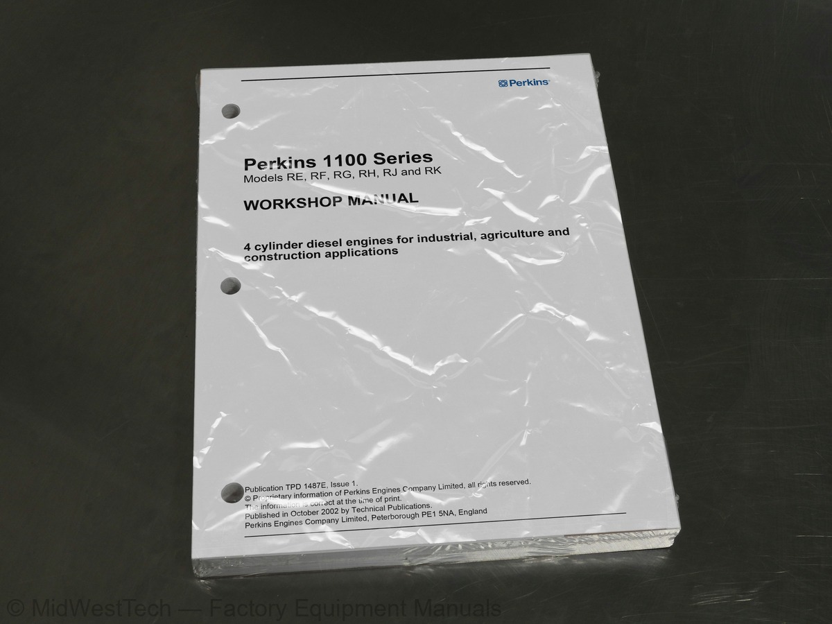
JCB Perkins 1100 Series Models RE, RF, RG, RH, RJ and RK Diesel Engine Service Manual
274 pages · Publication 9806-2250
Added to your cart. View cart
- Models
- Perkins 1100 Series Models RE, RF, RG, RH, RJ and RK Diesel
- Manual type
- Service Manual
- Pages
- 274
- Publication
- 9806-2250
- Condition
- Brand new
What's inside
From the manual's own table of contents: 112 sections, 189 entries. See sample pages (PDF, 305 KB)
Show all 112 sections
Lubrication system16 topics
- General description
- Lubrication system flow diagram
- Operation 10-1 To renew (canister type oil filter)
- Operation 10-2 To renew (element type oil filter)
- Operation 10-3 To remove and to fit
- Operation 10-4 To remove
- Operation 10-5 To fit
- Operation 10-6 To remove and to fit
- Operation 10-7 To remove and to fit
- Operation 10-8 To inspect and to correct
- Operation 10-9 To remove
- Operation 10-10 To fit
- Operation 10-11 To inspect
- Operation 10-12 To remove and to fit the relief valve of the balancer
- Operation 10-13 To remove and to fit the relief valve of the lubricating oil pump
- Operation 10-14 To inspect the relief valve of the lubricating oil pump/balancer
Fuel system16 topics
- Cold start advance unit (KSB)
- Typical fuel system
- Operation 11-1 To renew
- Operation 11-2 To identify a faulty atomiser
- Operation 11-3 To remove
- Operation 11-4 To fit
- Operation 11-5 To remove and to fit
- Operation 11-6 To test
- Operation 11-7 To test pressure regulator
- Operation 11-8 To eliminate air from the fuel system
- Operation 11-9 To remove
- Operation 11-10 To fit
- Operation 11-11 To remove
- Operation 11-12 To fit
- Operation 11-13 To remove
- Operation 11-14 To fit
Cooling system15 topics
- Coolant flow diagram
- Operation 12-1 To remove
- Operation 12-2 To fit
- Operation 12-3 To test
- Coolant pump
- Operation 12-4 To remove
- Operation 12-5 To fit
- Operation 12-6 To dismantle
- Operation 12-7 To assemble
- Operation 12-8 To remove and to fit
- Operation 12-9 To remove and to fit
- Operation 12-10 To remove
- Operation 12-11 To fit
- Operation 12-12 To dismantle and to assemble
- Operation 12-13 To remove and to fit a coolant by-pass pipe
Flywheel and housing3 topics
- Operation 13-1 To remove and to fit
- Operation 13-2 To remove and to fit
- Operation 13-3 To remove and to fit
Electrical equipment21 topics
- Operation 14-1 To check the drive belts
- Operation 14-2 To adjust drive belt tension
- Operation 14-3 To remove and to fit the drive belts
- Operation 14-4 To remove and to fit the alternator
- Operation 14-5 To maintain
- Operation 14-6 Fault diagnosis for the alternator
- Operation 14-7 To remove and to fit
- Operation 14-8 To maintain the brush gear and the commutator
- Operation 14-9 To test on the engine
- Operation 14-10 To remove and to fit a glow plug
- Operation 14-11 To check the glow plugs’ power supply continuity
- Operation 14-12 To check the operation of the glow plug
- Operation 14-13 To remove and to fit the Engine Control Module (ECM)
- Operation 14-14 To remove and to fit the Voltage Load Protection Module (VLPM)
- Operation 14-15 To program a new ECM
- Operation 14-16 To remove and to fit the speed and timing sensor
- Operation 14-17 To remove and to fit a pressure sensor
- Operation 14-18 To remove and to fit a temperature sensor
- Operation 14-19 To repair a sensor connector
- Operation 14-20 To repair a Diagnostic, a ECM, or a MIC connector
- Operation 14-21 To connect a new wire or connector to the wiring harness
Auxiliary equipment5 topics
- Operation 15-1 To remove and to fit
- Operation 15-2 To remove and to fit
- Operation 15-3 To dismantle
- Operation 15-4 To assemble
- Operation 15-5 To remove and to fit
Special tools1 topic
- List of special tools
Inside this manual
Real pages from this service manual (274 pages). Open the sample pages (PDF, 304 KB)
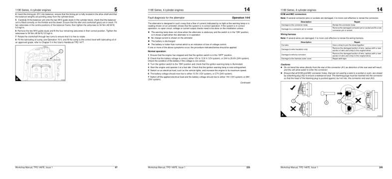
- Specifications, page 109: 7 Rotate the crankshaft through two turns to ensure that it is free to rotate.
- Troubleshooting, page 237: Fault diagnosis for the alternator
- Diagram, page 257: ECM and MIC connectors
This is a service manual
Here's how it compares to the other manual types.
Service manual
Factory repair procedures and technical information such as specifications, troubleshooting, and wiring and hydraulic diagrams, for the models and systems the manual covers. See What's inside for its topics.
Operator's manual
Safe operation, controls, maintenance schedules, lubrication points, inspections, and basic checks. Repair procedures are in the service manual.
Parts manual
Illustrated diagrams with factory part numbers for identifying components and ordering parts. Repair procedures are in the service manual.
Engine service manuals are sometimes sold separately, since certain machine models were offered with more than one engine option.
What it's used for
Factory manual for in-house farm and construction shop use. Straightforward, complete, and easy to follow. It contains the OEM information dealership service departments and parts counters use to diagnose problems, identify components, and perform maintenance or repairs correctly.
Service shops and owner/operators who repair their own equipment
Identifying correct parts and seeing how assemblies come apart and go back together
Keeping equipment running with less downtime
Factory manual, 274 pages
Quantity one is the manual described above.
Fast free USA shipping
Ships in 1 business day.
60-day returns
Free if the mistake is ours. A manual ordered in error must come back unopened in its shrink-wrap; you pay return shipping and a 20% restocking fee applies. Return policy
Other editions and similar models
Questions about model, serial number, engine coverage or contents? Contact us before purchasing and we'll help confirm it's the right manual. Please verify the manual type, machine model, serial number range and engine coverage before purchasing: manuals ordered in error carry a 20% restocking fee (return policy).