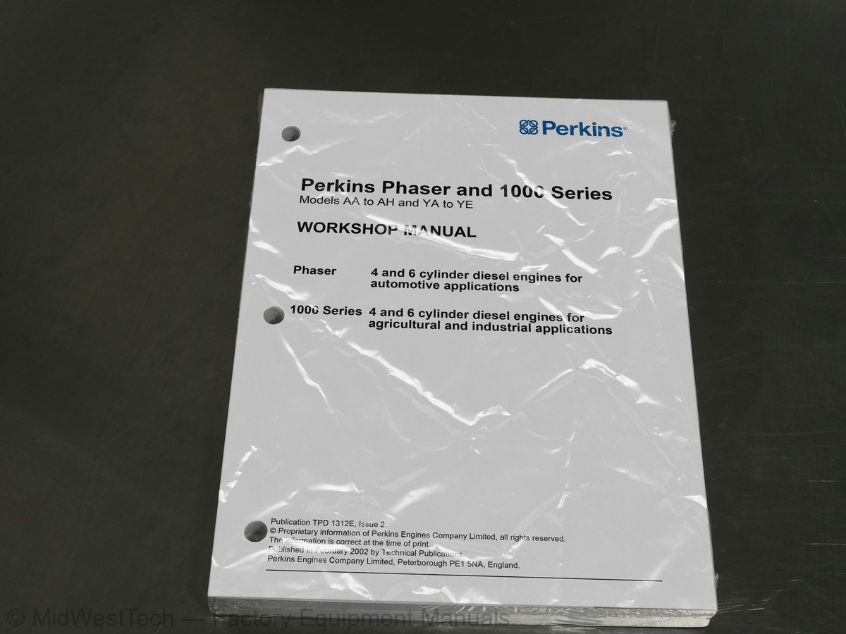
JCB Perkins Phaser 1000 Series AA-AH, YA-YE Diesel Engine Service Manual
440 pages · Publication TPD-1312E
Added to your cart. View cart
- Models
- Perkins Phaser 1000 Series AA-AH, YA-YE Diesel
- Manual type
- Service Manual
- Pages
- 440
- Publication
- TPD-1312E
- Condition
- Brand new
What's inside
From the manual's own table of contents: 153 sections, 283 entries. See sample pages (PDF, 318 KB)
General8 topics
- Introduction
- Engine views
- Engine identification
- Safety precautions
- Asbestos joints
- Viton seals
- Engine lift equipment
- POWERPART consumable products
Operation 3-19 To fit valve seat inserts9 topics
- Operation 4-11 To inspect
- Operation 4-12 To remove and to fit
- Operation 4-13 To remove and to fit
- Operation 4-14 To check the jet alignment
- General description
- Operation 5-1 To remove and to fit (four cylinder engines)
- Operation 5-2 To remove (six cylinder engines)
- Operation 5-3 To fit (six cylinder engines)
- Operation 5-4 To inspect
Show all 154 sections
Operation 6-5 To remove and to fit a wear sleeve23 topics
- Operation 6-6 To remove
- Operation 6-7 To fit
- Idler gear and hub for the Bendix or Knorr-Bremse compressor
- Operation 6-8 To remove
- Operation 6-9 To fit
- Operation 6-10 To remove
- Operation 6-11 To fit
- Operation 6-12 To remove
- Operation 6-13 To fit
- Operation 6-14 To remove and to fit
- Operation 6-15 To remove
- Operation 6-16 To fit
- Operation 6-17 To remove
- Operation 6-18 To fit
- Operation 7-1 To dismantle
- Operation 7-2 To assemble
- Operation 7-3 To inspect
- Operation 7-4 To remove and to fit a new type ‘D’ plug to the tappet chamber
- Operation 7-5 To inspect
- Operation 7-6 To recover a glazed liner
- Operation 7-7 To remove
- Operation 7-8 To fit a service liner
- Operation 7-9 To fit a partially finished liner
Turbocharger faults28 topics
- Open engine breather
- Operation 9-6 To remove, to fit and to clean (early type)
- Operation 9-7 To clean and to renew (Later type)
- Operation 9-8 To renew (Latest type)
- Operation 9-9 To Inspect
- Closed breather system
- Operation 9-10 To clean the early closed breather system
- Operation 9-11 To renew latest closed breather system
- Operation 9-12 To repair the connection for the latest breather outlet elbow
- General description (four cylinder engine lubrication system)
- General description (six cylinder engine lubrication system)
- Lubrication system flow diagram
- Lubrication system flow diagram for the relief valve and balancer
- Operation 10-1 To renew
- Operation 10-2 To remove and to fit
- Operation 10-3 To remove and to fit
- Operation 10-4 To remove and to fit
- Operation 10-5 To inspect and to correct
- Operation 10-6 To remove
- Operation 10-7 To fit
- Operation 10-8 To inspect
- Operation 10-9 To remove the idler shaft
- Operation 10-10 Alternative method to remove the idler shaft
- Operation 10-11 To fit the idler shaft (Six cylinder engines)
- Operation 10-12 To remove and to fit the idler shaft (four cylinder engines)
- Operation 10-13 To remove and to fit
- Operation 10-14 To dismantle and to assemble
- Operation 10-15 To inspect
Operation 11-18 To set38 topics
- Operation 11-19 To set the injection advance device (KSB)
- Operation 11-20 To adjust
- Operation 11-21 General description for pin timed fuel injection pump
- Operation 11-22 To remove pin timed fuel injection pump
- Operation 11-23 To fit pin timed fuel injection pump
- Operation 11-24 To adjust pin timed fuel injection pump
- Operation 11-25 To eliminate air from the fuel system
- Operation 11-26 To remove
- Operation 11-27 To fit
- Operation 11-28 To adjust the fuel injection pump
- Operation 11-29 To remove and fit the adaptor plate for the fuel injection pump
- Operation 11-30 To eliminate air from the fuel system
- Operation 11-31 To remove
- Operation 11-32 To fit
- Operation 11-33 To adjust
- Operation 11-34 Electrical shut off solenoid (ESOS)
- Operation 11-35 To eliminate air from the fuel system
- Operation 11-36 Standard method
- Operation 11-37 Self-vent method
- Lucas/Delphi DP 200 Series fuel injection pump
- Operation 11-38 To remove
- Operation 11-39 To fit
- Operation 11-40 To adjust
- Operation 11-41 General description for pin timed fuel injection pump
- Operation 11-42 To remove pin timed fuel injection pump
- Operation 11-43 To fit pin timed fuel injection pump
- Operation 11-44 To adjust pin timed fuel injection pump
- Operation 11-45 Electrical shut off solenoid (ESOS)
- Operation 11-46 To eliminate air from the fuel system
- Stanadyne fuel injection pump
- Operation 11-47 To remove
- Operation 11-48 To fit
- Operation 11-49 To adjust
- Operation 11-50 General description for pin timed fuel injection pump
- Operation 11-51 To remove pin timed fuel injection pump
- Operation 11-52 To fit pin timed fuel injection pump
- Operation 11-53 To adjust pin timed fuel injection pump
- Operation 11-54 To eliminate air from the fuel system
Operation 12-29 To remove and to fit24 topics
- Intercooler
- Operation 12-30 To remove
- Operation 12-31 To fit
- Operation 12-32 To clean and to inspect
- Operation 13-1 To remove and to fit
- Operation 13-2 To remove and to fit
- Operation 13-3 To remove and to fit
- Operation 14-1 To check the drive belts
- Operation 14-2 To adjust belt tension
- Operation 14-3 To remove and to fit the drive belts
- Operation 14-4 To remove and to fit the alternator
- Operation 14-5 To maintain the alternator
- Alternator fault diagnosis
- Operation 14-6 To remove and to fit
- Operation 14-7 To maintain the brush gear and the commutator
- Operation 14-8 To test on the engine
- Operation 14-9 To remove and to fit a fuelled starting aid
- Operation 14-10 To remove and to fit a twin fuelled starting
- Operation 14-11 How to check the fuelled starting aid
- Operation 14-12 To remove and to fit a port heater
- Operation 15-1 To remove the earliest compressor and drive assembly
- Operation 15-2 To fit the earliest compressor and drive assembly
- Operation 15-3 To fit the early compressor and drive assembly
- Operation 15-4 To fit the early compressor only
Inside this manual
Real pages from this service manual (440 pages). Open the sample pages (PDF, 317 KB)
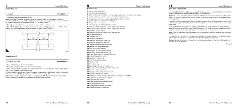
- Specifications, page 98: Connecting rod
- Troubleshooting, page 224: Possible causes
- Diagram, page 260: Cold start advance unit
This is a service manual
Here's how it compares to the other manual types.
Service manual
Factory repair procedures and technical information such as specifications, troubleshooting, and wiring and hydraulic diagrams, for the models and systems the manual covers. See What's inside for its topics.
Operator's manual
Safe operation, controls, maintenance schedules, lubrication points, inspections, and basic checks. Repair procedures are in the service manual.
Parts manual
Illustrated diagrams with factory part numbers for identifying components and ordering parts. Repair procedures are in the service manual.
Engine service manuals are sometimes sold separately, since certain machine models were offered with more than one engine option.
What it's used for
Factory manual for in-house farm and construction shop use. Straightforward, complete, and easy to follow. It contains the OEM information dealership service departments and parts counters use to diagnose problems, identify components, and perform maintenance or repairs correctly.
Service shops and owner/operators who repair their own equipment
Identifying correct parts and seeing how assemblies come apart and go back together
Keeping equipment running with less downtime
Factory manual, 440 pages
Quantity one is the manual described above.
Fast free USA shipping
Ships in 1 business day.
60-day returns
Free if the mistake is ours. A manual ordered in error must come back unopened in its shrink-wrap; you pay return shipping and a 20% restocking fee applies. Return policy
Binder not included
Manuals over about 300 pages may need a standard 3-ring binder, which you can buy locally to keep the pages organized for shop use.
Other editions and similar models
Questions about model, serial number, engine coverage or contents? Contact us before purchasing and we'll help confirm it's the right manual. Please verify the manual type, machine model, serial number range and engine coverage before purchasing: manuals ordered in error carry a 20% restocking fee (return policy).