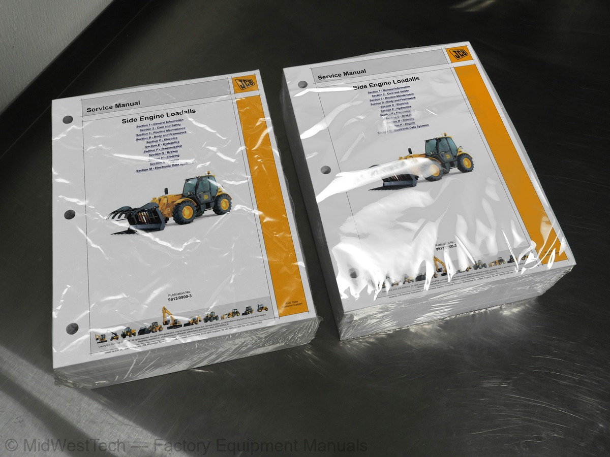
JCB Side Engine Loadall 5A, 5T, 531-70, 535-95, 536-60, 541-70, 533-105, 536-70, 526-56 and 7 more Telehandler Service Manual
2,947 pages · Publication 9813-0900-3 · Side Engine Loadall 5A, 5T, 531-70, 535-95, 536-60, 541-70, 533-105, 536-70, 526-56, 550-80, 531-T70, 541-T70, 536-T60, 535-T95, 536-T70, 550-T80
Added to your cart. View cart
What's inside
From the manual's own table of contents: 277 topics. See sample pages (PDF, 435 KB)
- Introduction
- Scope
- Format
- Left and Right Sides
- Hydraulic Schematic Codes
- Related Topics
- Machine Identification Plate
- Component Identification Plates
- Zinc Plated Fasteners and Dacromet Fasteners
- Hydraulic Connections
- `Positional Type' Hydraulic Adaptors
- Numerical List
- Tool Detail Reference
- Rivet Nuts
- Slide Hammer Kit
- Sealing and Retaining Compounds
- Acceptable and Unacceptable Fuels
- Specifications
- Important Information
- Safety Check List
- Safety Decals
- Parking the Machine and Making it Safe
- Boom Safety Strut (P1)
- Boom Safety Strut (P2)
Show all 277 topics
- Venting the Hydraulic Pressure
- Venting the Brake System Pressure
- Connecting/Disconnecting Hydraulic Hoses
- Quick Release Couplings
- Hydraulic Contamination
- Battery Disconnection/Connection
- Removing and Replacing Components
- Battery Charging System Precautions
- Hydraulic Rams
- Gas Hydraulic Bladder Accumulators
- Table
- Applicability
- Service Requirements
- Health and Safety
- Service Schedules
- Fluids, Lubricants and Capacities
- Prepare the Machine for Maintenance
- Cleaning the Machine
- Checking for Damage
- Greasing
- Access Panels
- Cab Heater and Air Conditioning
- Boom
- Brakes
- Electrical System
- Engine
- Fuel System
- Hydraulic System
- Transmission
- Tyres and Wheels
- Wheel Alignment
- Wear Pads
- Windscreen Washer
- Fire Extinguisher (if fitted)
- Oiling
- Removal and Replacement
- Component Location
- Operation Overview
- Electrical Operation and Schematics
- Fault Finding
- Refrigerant
- Component Locations
- Fault Finding and Diagnostics
- Test Procedures
- Compressor Drive Belt - Adjustment
- Hydraulic Operation and Schematics
- LLMI - Calibration
- LLMI Tests
- LLMC Tests
- Freeze Thermostat (HVAC Unit)
- Removal and Replacement (P1)
- Removal and Replacement (P2)
- Testing
- Wear Pads and Shims
- Angle Indicator Removal and Replacement
- Pivot Shims
- Dismantling and Assembly
- Leg Removal and Replacement (P1)
- Leg Removal and Replacement (P2)
- Leg Removal and Replacement (P3)
- Frame Removal and Replacement
- Checking Pressure Switch Operation
- Spool Sensors (Parallel Machines)
- Boom Mounted Inclinometer P1
- Boom Mounted Inclinometer P2
- Boom Mounted Inclinometer P3
- Chassis Mounted Inclinometer P1
- Chassis Mounted Inclinometer P2
- Chassis Mounted Inclinometer P3
- Chassis Mounted Inclinometer P4
- Boom Retract Sensor
- Boom Extended Sensor
- Access and Location (P1)
- Access and Location (P2)
- Fuses - SD, SF Engines, 4 Speed PS (S1)
- Fuses - SD, SF Engines, 4 Speed PS (S2)
- Fuses - SE Engines, 4 Speed PS (S1)
- Fuses SE Engines, 4 Speed PS (S2)
- Fuses - SE Engines, 6 Speed PS (S1)
- Fuses - SE Engines, 6 Speed PS (S2)
- Fuses - SD, SF Engines, 4 Speed PS (S3)
- Fuses - SD, SF Engines, 4 Speed SS
- Link Box Fuses
- Cab Auxiliary Power Fuse
- Relays - SD, SF Engines, 4 Speed PS (S1)
- Relays - SD, SF Engines, 4 Speed PS (S2)
- Relays - SE Engines, 4 Speed PS (S1)
- Relays - SE Engines, 4 Speed PS (S2)
- Relays - SE Engines, 6 Speed PS (S1)
- Relays - SE Engines, 6 Speed PS (S2)
- Relays - SD, SF Engines, 4 Speed PS (S3)
- Relays - SD, SF Engines, 4 Speed SS
- Fusebox Pin Number Identification (S1)
- Fusebox Pin Number Identification (S2)
- Relay Base Pin Number Identification
- Overview
- Applications
- Electrical Schematic
- Earth Points
- Wire Numbers and Functions
- Harness Interconnections and Drawings
- Wiring Harness Repair
- Removal, Inspection and Replacement
- Dismantle and Assemble
- Maintenance
- Disconnection and Connection
- Systems
- Schematics - Parallel System with Dual Lever Controls
- Schematics - Parallel System with Single Lever Controls
- Schematics - LSP Electro Servo System (S1)
- Schematics - LSP Electro Servo System (S2)
- Schematics - LSP Electro Servo System (S3)
- Schematics - LSP Electro Servo System (S4)
- Parallel Lift (S1)
- Parallel Lift (S2)
- Lift Pressure Balance System (S1)
- Lift Pressure Balance System (S2)
- Tilt/Lift/Extension Ram Counterbalance Valves
- Checking Pump Flow
- Electrical Operation and Schematics (S1)
- Electrical Operation and Schematics (S2)
- Electrical Operation and Schematics (S3)
- Pump Control
- Dismantle, Inspection and Assemble
- Steering Priority Valve
- Removal and Replacement (S1)
- Removal and Replacement (S2)
- Removal and Replacement - Single Ram (P1)
- Removal and Replacement - Single Ram (P2)
- Removal and Replacement - Single Ram (P3)
- Removal and Replacement - Twin Rams, 2 Stage Boom
- Removal and Replacement - Twin Rams, 3 Stage Boom
- Removal and Replacement - Twin Rams, 5 Stage Boom
- Removal and Replacement - 2 Stage Boom (P1)
- Removal and Replacement - 2 Stage Boom (P2)
- Removal and Replacement - 2 Stage Boom (P3)
- Removal and Replacement - 3, 4 and 5 Stage Boom
- Removal and Replacement - 3 Stage Boom
- Single Piston Rams
- Piston Head Retention
- Twin Piston, 4 Stage Boom Outer Ram
- Extension Ram Make-Up Valve (if fitted)
- Electrical Connectors
- Accumulator Charging and Discharging
- Accumulator Removal and Replacement (S1)
- Accumulator Removal and Replacement (S2)
- Bleed Procedure
- Component Identification
- Renewing the Pinion Oil Seal
- Removal and Replacement - Fixed Axle
- Removal and Replacement - Sway Axle
- Dismantle, Inspection and Assembly
- Service Tools
- Dismantle and Assembly - Introduction
- Dismantle and Assembly - Service Brakes
- Removal - Differential Unit
- Replacement - Differential Unit
- Dismantle - Differential Unit
- Assembly - Differential Unit
- Removal and Dismantle - Limited Slip Differential
- Assembly and Replacement - Limited Slip Differential
- Removal - Pinion
- Replacement - Pinion
- Dismantle - Planetary Hub
- Assembly - Planetary Hub
- Removal and Replacement - Steering Swivel
- Removal - Driveshaft
- Replacement - Driveshaft
- Removal and Replacement - SD55 Axle
- Removal and Dismantle - Differential Unit
- Assembly and Replacement - Differential Unit
- Dismantle and Assembly - Pinion
- Dismantle and Assembly - Planetary Hub
- Dismantle and Assembly - Trunnion Support
- Removal and Dismantle - Driveshaft
- Assembly and Replacement - Driveshaft
- Drive Paths
- Descriptions
- Clutch Operation Overview
- Forward and Reverser Clutch Operation
- Mainshaft and Layshaft Clutch Operation
- and 4 Wheel Drive Clutch (4WD Spring ON) Operation (if fitted)
- Gear Operation Overview
- Electronic Fault Codes
- Gearbox `Limp Modes' (Powershift Electronic Control)
- Transmission Technical Data Check List
- Pressure and Flow Tests
- Procedure
- Renewing the ECU
- Oil Pressure Switch - Removal and Replacement
- Solenoid Control Valves - Removal and Replacement
- Wheel Drive Yoke and Oil Seal - Removal and Replacement
- Gearbox Removal and Replacement
- Gearbox Dismantle, Inspection and Assembly
- Solenoid Control Valve Cartridge - Solenoid Coil
- Solenoid Control Valve Cartridge - Twin Fixing Type
- Oil Pressure Switch
- Oil Temperature Switch (P1)
- Oil Temperature Switch (P2)
- Removal, Testing and Replacement
- Axle Breather (Braked Axles) - Inspection
- Bleeding
- Brake Light Switch - (Proximity Type)
- Brake Light Switch (Reed Type)
- Lever Adjustment
- Switch Adjustment
- Renewing the Brake Pads
- Renewing the Parkbrake Cable
- Adjustment
- Re-phasing the Road Wheels
- Bleeding the System
- Proximity Switch - Setting
- Electrical Operation and Schematics - Indicated System (if fitted)
- Removal and Replacement (S3)
- Link Arms
- Removal
- Replacement
- Dismantle
- Assembly
- Removal and Replacement (P3)
- Removal and Replacement (P4)
- Renewing the Brush Gear
- Renewing the Starter Solenoid
- Separating the Engine and Bevel Box
- Service Hours Reset
- General ‘D’ Codes
- Transmission ‘T’ Codes
- Powertrain ‘P’ Codes
- Constant Auxiliary ECU ‘A’ Codes
- HVCS ‘H’ Codes
- Machine Control ECU ‘L’ Codes
- Cab Area ‘B’ Codes
- Chassis ‘C’ Codes
- CANbus ‘U’ Codes
- RAS “S” Codes
- Electronic Engine SE Engine ECU Codes
- Electronic Engine SH/SL/DH Engine ECU Codes
- Why Use ServiceMaster?
- What is Servicemaster?
- How to Set Up Servicemaster
- Tool Suite
- Diagnostics Connector
- Servicemaster Machine Selection
- JCB 4.4L Tier 3 SE Diagnostics Tool - User Guide
- JCB 4.4L Tier 3 SE Engine Setup - User Guide
- User Guide
- Loadall LMS Setup - User Guide
- Loadall Datalogger - User Guide
- Loadall Machine Diagnostics - User Guide
- Boom Angle Sensor Calibration - User Guide
- Location
- Wires and Connectors
- Removal and Replacement Guide
Inside this manual
Real pages from this service manual (2,947 pages). Open the sample pages (PDF, 434 KB)

- Specifications, page 165: Section 3-1 - Routine Maintenance
- Diagram, page 2,100: Section F23 - Transmission
- Troubleshooting, page 2,685: Section M2 - Electronic Network
- Color page, page 1,258: Section E6 - Hydraulics
- Color page, page 1,108: Section E3 - Hydraulics
This is a service manual
Here's how it compares to the other manual types.
Service manual
Factory repair procedures and technical information such as specifications, troubleshooting, and wiring and hydraulic diagrams, for the models and systems the manual covers. See What's inside for its topics.
Operator's manual
Safe operation, controls, maintenance schedules, lubrication points, inspections, and basic checks. Repair procedures are in the service manual.
Parts manual
Illustrated diagrams with factory part numbers for identifying components and ordering parts. Repair procedures are in the service manual.
Engine service manuals are sometimes sold separately, since certain machine models were offered with more than one engine option.
What it's used for
Factory manual for in-house farm and construction shop use. Straightforward, complete, and easy to follow. It contains the OEM information dealership service departments and parts counters use to diagnose problems, identify components, and perform maintenance or repairs correctly.
Service shops and owner/operators who repair their own equipment
Identifying correct parts and seeing how assemblies come apart and go back together
Keeping equipment running with less downtime
Factory manual, 2,947 pages
Quantity one is the manual described above.
Fast free USA shipping
Ships in 1 business day.
60-day returns
Free if the mistake is ours. A manual ordered in error must come back unopened in its shrink-wrap; you pay return shipping and a 20% restocking fee applies. Return policy
Binder not included
Manuals over about 300 pages may need a standard 3-ring binder, which you can buy locally to keep the pages organized for shop use.
Other editions and similar models
Questions about model, serial number, engine coverage or contents? Contact us before purchasing and we'll help confirm it's the right manual. Please verify the manual type, machine model, serial number range and engine coverage before purchasing: manuals ordered in error carry a 20% restocking fee (return policy).